Petruzella F.D. Programmable Logic Controllers
Подождите немного. Документ загружается.

Programming Timers Chapter 7 143
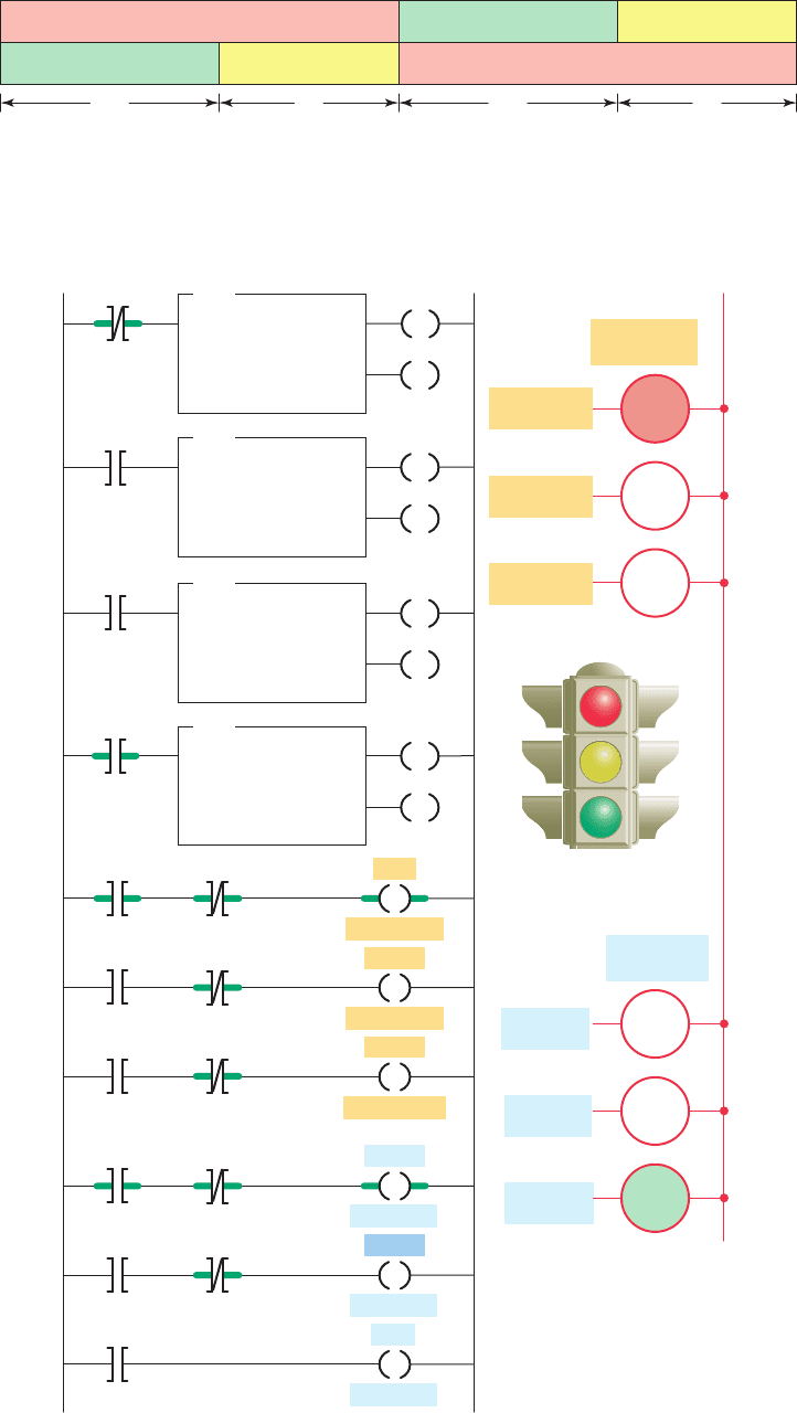
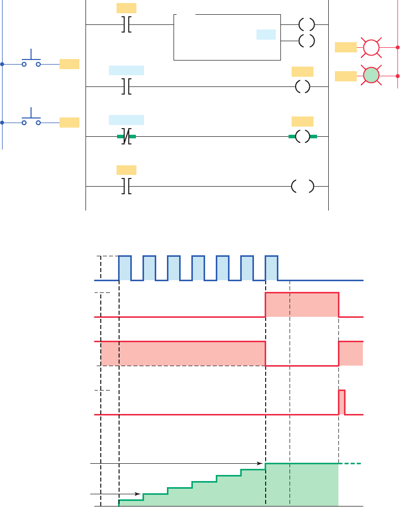
Figure 7-35 Timing chart for two-directional control of traffi c lights.
Red ⫽ north/south
Red ⫽ east/westGreen ⫽ east/west
25 s
Amber ⫽ east/west
5 s
Green ⫽ north/south Amber ⫽ north/south
25 s
5 s
Figure 7-36 Control of traffi c lights in two directions.
North/south
North/south
North/south
Red
East/west
Amber
East/west
Green
East/west
Red
North/south
Amber
North/south
Green
North/south
North/south
traffic lights
East/west
traffic lights
Green
Amber
Red
East/west
East/west
East/west
T4:2
DN
Ladder logic program
T4:0
1. 0
30
0
TON
TIMER ON DELAY
Timer
Time base
Preset
Accumulated
DN
T4:0
DN
T4:1
1. 0
25
0
TON
TIMER ON DELAY
Timer
Time base
Preset
Accumulated
EN
DN
T4:1
T4:2
1. 0
5
0
TON
TIMER ON DELAY
Timer
Time base
Preset
Accumulated
EN
DN
T4:0
EN
T4:0
Red
T4:1
EN
T4:1
Green
T4:2
EN
T4:2
Amber
L1
Outputs
Green
Amber
Red
Green
Amber
EN
DN
DN
DN
DN
T4:0
T4:3
1. 0
25
0
TON
TIMER ON DELAY
Timer
Time base
Preset
Accumulated
EN
DN
EN
T4:3
EN
T4:3
T4:3
DN
T4:0
T4:0
DN
DN
DN
Red
pet10882_ch07_125-148.indd 143pet10882_ch07_125-148.indd 143 7/23/10 9:36 PM7/23/10 9:36 PM
144 Chapter 7 Programming Timers
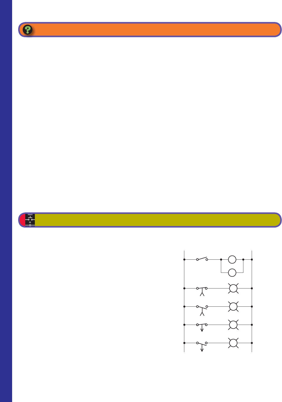
Figure 7-37 Relay schematic diagram for Problem 1.
Relay schematic diagram
L2
TD2-2
L1
TD1
TD2
S1
(5 s)
TD1-1
(5 s)
TD1-2
(5 s)
TD2-1
(5 s)
PL4
PL3
PL2
PL1
1. Explain the difference between the timed and
instantaneous contacts of a mechanical timing
relay.
2. Draw the symbol and explain the operation of each
of the following timed contacts of a mechanical
timing relay:
a. On-delay timer—NOTC contact
b. On-delay timer—NCTO contact
c. Off-delay timer—NOTO contact
d. Off-delay timer—NCTC contact
3. Name ve pieces of information usually associated
with a PLC timer instruction.
4. When is the output of a programmed timer
energized?
5. a. What are the two methods commonly used to
represent a timer instruction within a PLC’s
ladder logic program?
b. Which method is preferred? Why?
6. a. Explain the difference between the operation of
a nonretentive timer and that of a retentive timer.
b. Explain how the accumulated count of pro-
grammed retentive and nonretentive timers is
reset to zero.
7. State three advantages of using programmed PLC
timers over mechanical timing relays.
8. For a TON timer:
a. When is the enable bit of a timer instruction
true?
b. When is the timer-timing bit of a timer instruc-
tion true?
c. When does the done bit of a timer change state?
9. For a TOF timer:
a. When is the enable bit of a timer instruction true?
b. When is the timer-timing bit of a timer instruc-
tion true?
c. When does the done bit of a timer change state?
10. Explain what each of the following quantities asso-
ciated with a PLC timer instruction represents:
a. Preset time
b. Accumulated time
c. Time base
11. State the method used to reset the accumulated
time of each of the following:
a. TON timer
b. TOF timer
c. RTO timer
CHAPTER 7 REVIEW QUESTIONS
1. a. With reference to the relay schematic diagram in
Figure7-37 , state the status of each light (on or
off) after each of the following sequential events:
i. Power is rst applied and switch S1 is open.
ii. Switch S1 has just closed.
iii. Switch S1 has been closed for 5 s.
iv. Switch S1 has just opened.
v. Switch S1 has been opened for 5 s.
b. Design a PLC program and prepare a typical I/O
connection diagram and ladder logic program that
will execute this hardwired control circuit correctly.
2. Design a PLC program and prepare a typical I/O
connection diagram and ladder logic program that
will correctly execute the hardwired relay control
circuit shown in Figure7-38 .
3. Study the ladder logic program in Figure7-39 and
answer the questions that follow:
a. What type of timer has been programmed?
b. What is the length of the time-delay period?
CHAPTER 7 PROBLEMS
pet10882_ch07_125-148.indd 144pet10882_ch07_125-148.indd 144 7/23/10 9:36 PM7/23/10 9:36 PM
Programming Timers Chapter 7 145
Figure 7-38 Hardwired relay control circuit for Problem 2.
L2
(60 s)
L1
PB1
PB2
Stop
Start
M-1
PS1
OL
Hand
Auto
TD-2
TD-1
TD
M
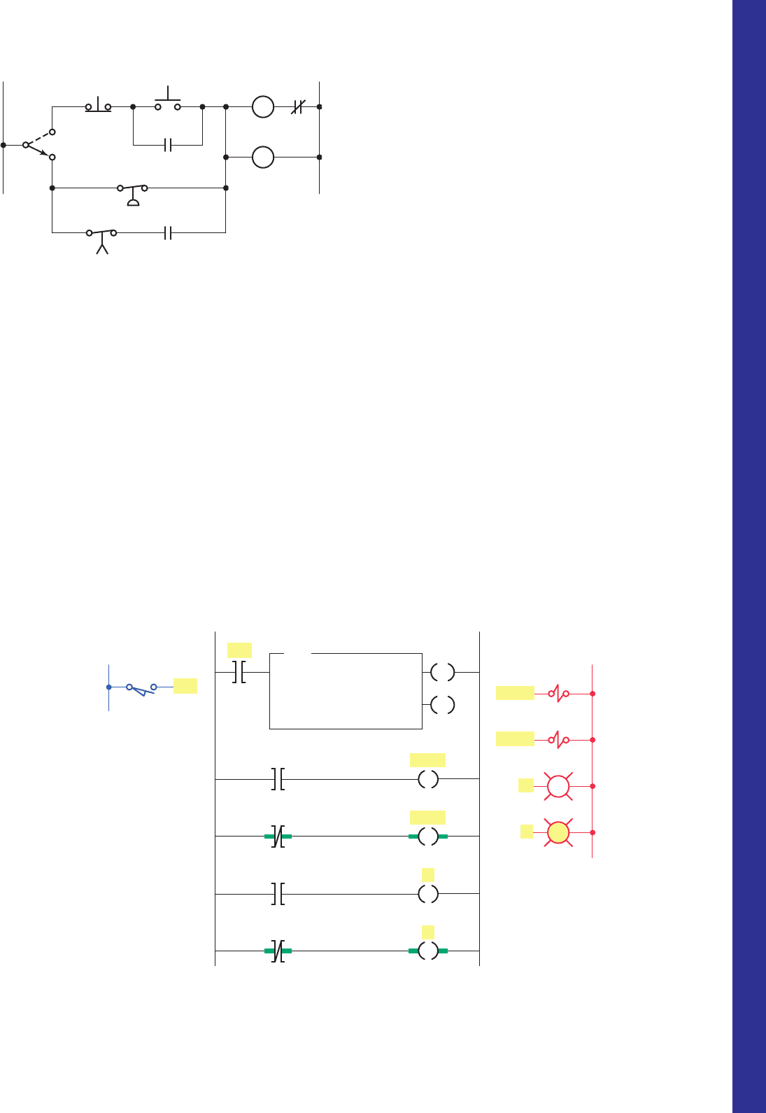
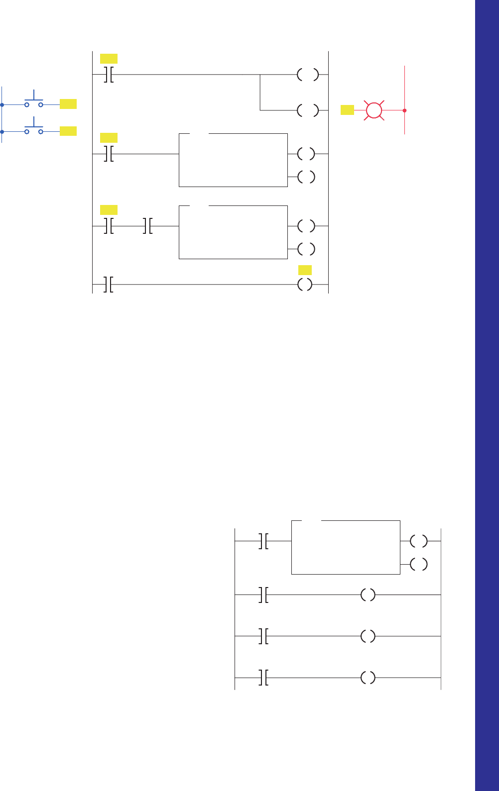
Figure 7-39 Ladder logic program for Problem 3.
L1
L2
LS1
LS1
Ladder logic programInput Outputs
T4:0
1
10
0
TON
TIMER ON DELAY
Timer
Time base
Preset
Accumulated
EN
DN
DN
DN
EN
EN
T4:0
T4:0
T4:0
T4:0
SOL A
SOL B
R
Y
1
2
3
4
5
SOL A
SOL B
R
Y
R
Y
c. What is the value of the accumulated time when
power is rst applied?
d. When does the timer start timing?
e. When does the timer stop timing and reset itself?
f. When input LS1 is rst closed, which rungs are
true and which are false?
g. When input LS1 is rst closed, state the status
(on or off) of each output.
h. When the timer’s accumulated value equals the
preset value, which rungs are true and which are
false?
i. When the timer’s accumulated value equals the
preset value, state the status (on or off) of each
output.
j. Suppose that rung 1 is true for 5 s and then
power is lost. What will the accumulated value
of the counter be when power is restored?
4. Study the ladder logic program in Figure7-40 and
answer the questions that follow:
a. What type of timer has been programmed?
b. What is the length of the time-delay period?
c. What is the value of the accumulated time when
power is rst applied?
d. When does the timer start timing?
e. When does the timer stop timing and reset itself?
f. When input LS1 is rst closed, which rungs are
true and which are false?
g. When input LS1 is rst closed, state the status
(on or off) of each output.
h. When the timer’s accumulated value equals the pre-
set value, which rungs are true and which are false?
i. When the timer’s accumulated value equals the
preset value, state the status (on or off) of each
output.
j. Suppose that rung 1 is true for 5 s and then
power is lost. What will the accumulated value
of the counter be when power is restored?
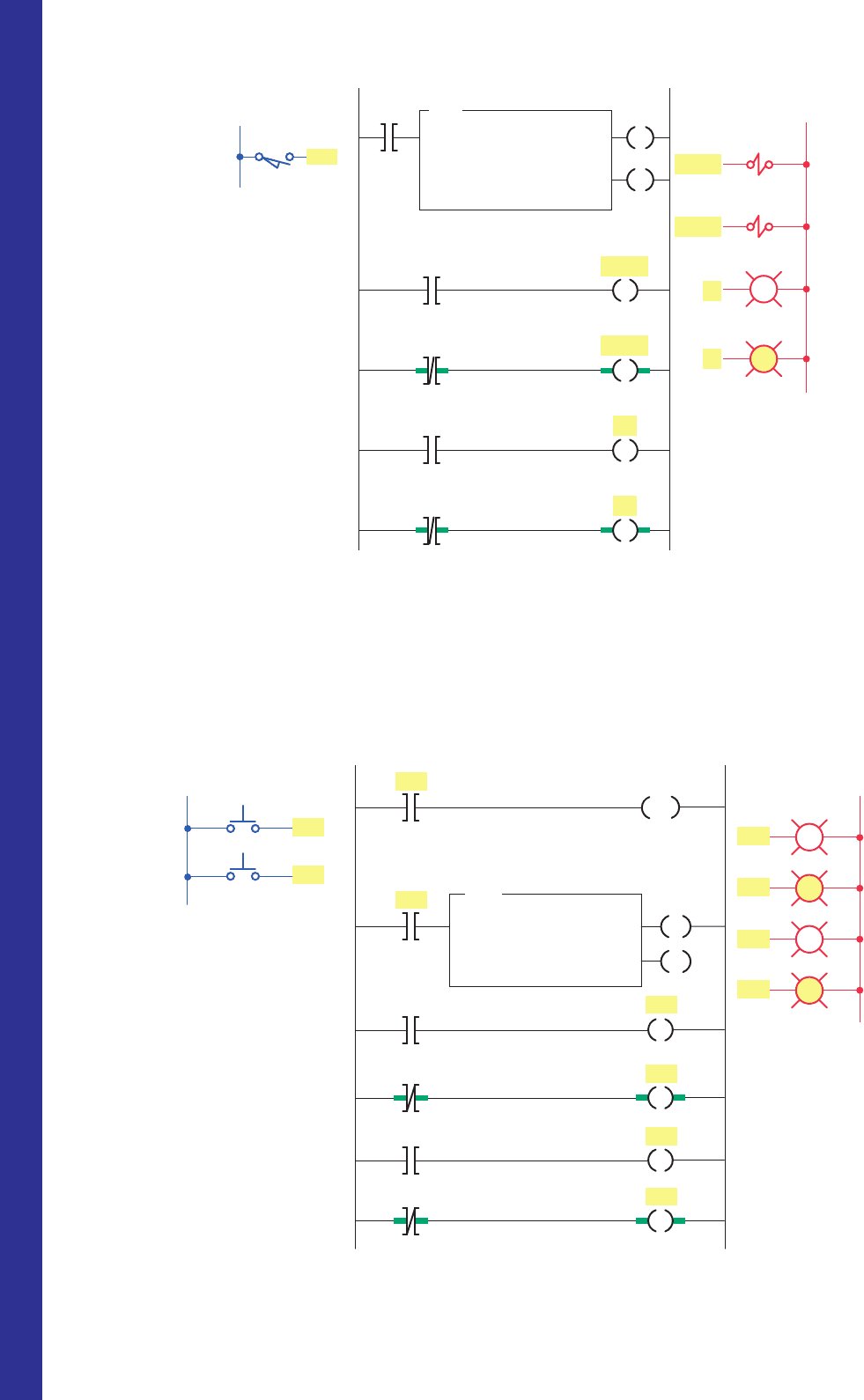
5. Study the ladder logic program in Figure7-41 , and
answer the questions that follow:
a. What type of timer has been programmed?
b. What is the length of the time-delay period?
c. When does the timer start timing?
pet10882_ch07_125-148.indd 145pet10882_ch07_125-148.indd 145 7/23/10 9:36 PM7/23/10 9:36 PM
146 Chapter 7 Programming Timers
Figure 7-41 Ladder logic program for Problem 5.
PL2
T4:5/EN
L1
Ladder logic programInputs
PB2
PB1
PB2
PB1
T4:5
1.0
50
0
RTO
RETENTIVE TIMER ON
Timer
Time base
Preset
Accumulated
PL1
T4:5/EN
PL4
L2
Outputs
PL4
PL3
PL2
PL1
T4:5 DN
PL3
T4:5 DN
1
2
3
4
5
6
RES
T4:5
EN
DN
Figure 7-40 Ladder logic program for Problem 4.
5
4
3
2
1
DN
Input
L1
LS1
LS1
Ladder logic program
T4:0
1
25
0
TOF
TIMER OFF DELAY
Timer
Time base
Preset
Accumulated
EN
SOL A
SOL B
R
Y
T4:0
DN
T4:0
DN
T4:0
EN
T4:0
EN
R
SOL B
Outputs
L2
Y
SOL A
Y
R
d. When is the timer reset?
e. When will rung 3 be true?
f. When will rung 5 be true?
g. When will output PL4 be energized?
h. Assume that your accumulated time value is up
to 020 and power to your system is lost. What
will your accumulated time value be when
power is restored?
pet10882_ch07_125-148.indd 146pet10882_ch07_125-148.indd 146 7/23/10 9:36 PM7/23/10 9:36 PM
Programming Timers Chapter 7 147
b. The input is true, and EN is 1, TT is 1, and
DNis 1.
c. The input is false, and EN is 0, TT is 0, and
DNis 0.
d. The input is true, and EN is 1, TT is 0, and
DNis 1.
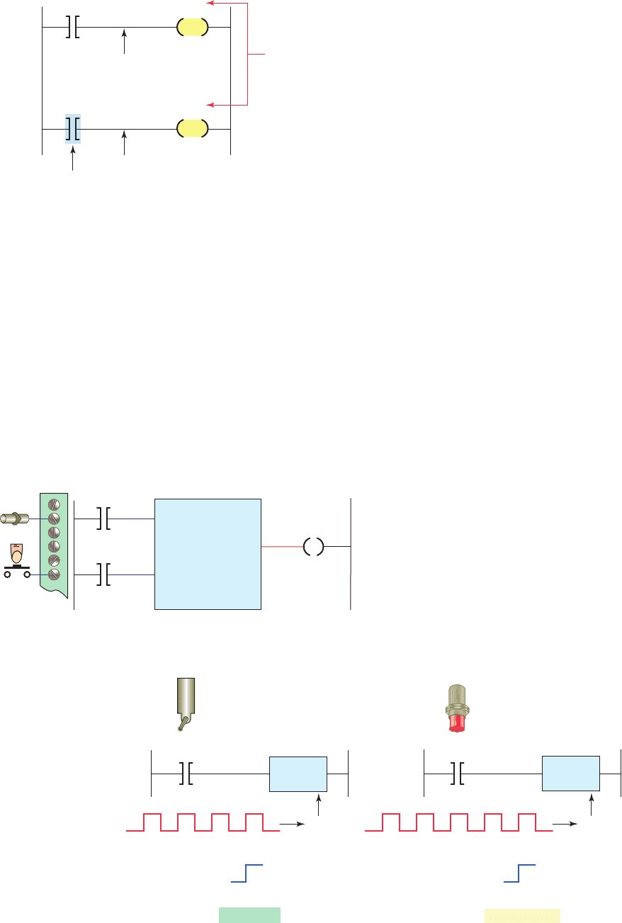
10. Study the off-delay timer ladder logic program in
Figure7-44 , and from each of the conditions stated,
determine whether the timer is reset, timing, or
timed out or if the conditions stated are not possible.
a. The input is true, and EN is 0, TT is 0, and
DNis 1.
i. What happens if inputs PB1 and PB2 are both
true at the same time?
6. Study the ladder logic program in Figure7-42 and
answer the questions that follow:
a. What is the purpose of interconnecting the two
timers?
b. How much time must elapse before output PL is
energized?
c. What two conditions must be satis ed for timer
T4:2 to start timing?
d. Assume that output PL is on and power to the
system is lost. When power is restored, what will
the status of this output be?
e. When input PB2 is on, what will happen?
f. When input PB1 is on, how much accumulated
time must elapse before rung 3 will be true?
7. You have a machine that cycles on and off during
its operation. You need to keep a record of its total
run time for maintenance purposes. Which timer
would accomplish this?
8. Write a ladder logic program that will turn on a
light, PL, 15 s after switch S1 has been turned on.
9. Study the on-delay timer ladder logic program
in Figure7-43 , and from each of the conditions
stated, determine whether the timer is reset, tim-
ing, or timed out or if the conditions stated are not
possible.
a. The input is true, and EN is 1, TT is 1, and
DNis 0.
Figure 7-42 Ladder logic program for Problem 6.
T4:2
T4:1
L1
PB1
PB2
PB2
PB1
PB1
Inputs
T4:1
1.0
2900
0
RTO
RETENTIVE TIMER ON
Timer
Time base
Preset
Accumulated
EN
DN
T4:2
1.0
1780
0
RTO
RETENTIVE TIMER ON
Timer
Time base
Preset
Accumulated
EN
DN
DN
DN
PL
L2
Output
PL
RES
RES
T4:2
T4:1
Ladder logic program
1
2
3
4
Figure 7-43 On-delay timer ladder logic program for
Problem 9.
Input
T4:0
1.0
10
0
TON
TIMER ON DELAY
Timer
Time base
Preset
Accumulated
EN
DN
T4:0
T4:0
T4:0
DN
EN
T T
pet10882_ch07_125-148.indd 147pet10882_ch07_125-148.indd 147 7/23/10 9:36 PM7/23/10 9:36 PM

148 Chapter 7 Programming Timers
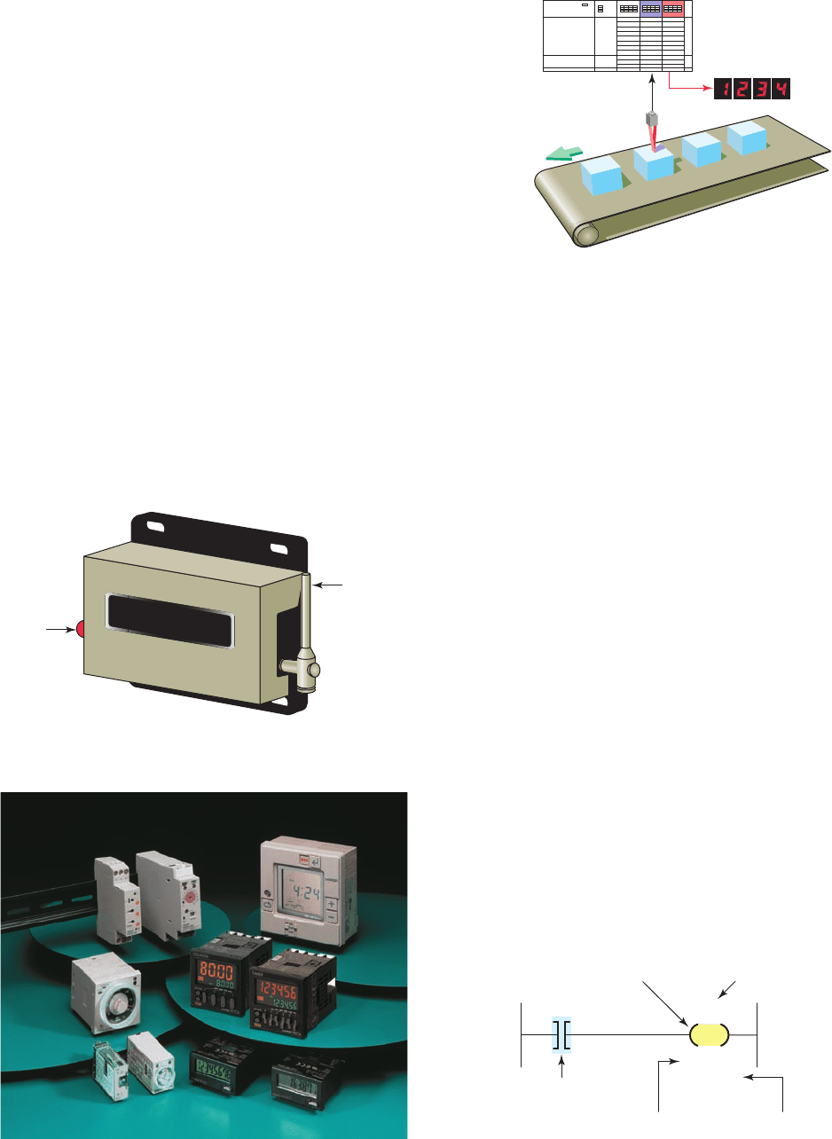
• Solenoid A is de-energized.
• The agitate motor starts automatically and runs
for 3 min to mix the liquid.
• When the agitate motor stops, solenoid B is ener-
gized to empty the tank.
• When the tank is completely empty, the empty
sensor switch opens to de-energize solenoid B .
• The start button is pressed to repeat the sequence.
14. When the lights are turned off in a building, an exit
door light is to remain on for an additional 2 min,
and the parking lot lights are to remain on for an
additional 3 min after the door light goes out. Write
a program to implement this process.
15. Write a program to simulate the operation of a se-
quential taillight system. The light system consists
of three separate lights on each side of the car. Each
set of lights will be activated separately, by either
the left or right turn signal switch. There is to be a
1 s delay between the activation of each light, and
a 1-s period when all the lights are off. Ensure that
when both switches are on, the system will not op-
erate. Use the least number of timers possible. The
sequence of operation should be as follows:
• The switch is operated.
• Light 1 is illuminated.
• Light 2 is illuminated 1 s later.
• Light 3 is illuminated 1 s later.
• Light 3 is illuminated for 1 s.
• All lights are off for 1 s.
• The system repeats while the switch is on.
b. The input is true, and EN is 1, TT is 1, and
DNis 1.
c. The input is true, and EN is 1, TT is 0, and
DNis 1.
d. The input is false, and EN is 0, TT is 1, and
DNis 1.
e. The input is false, and EN is 0, TT is 0, and
DNis 0.
11. Write a program for an “anti–tie down circuit” that
will disallow a punch press solenoid from operat-
ing unless both hands are on the two palm start
buttons. Both buttons must be pressed at the same
time within 0.5 s. The circuit also will not allow the
operator to tie down one of the buttons and operate
the press with just one button. (Hint: Once either of
the buttons is pressed, begin timing 0.5 s. Then, if
both buttons are not pressed, prevent the press sole-
noid from operating.)
12. Modify the program for the control of traf c lights
in two directions so that there is a 3-s period when
both directions will have their red lights illuminated.
13. Write a program to implement the process illus-
trated in Figure7-45 . The sequence of operation is
to be as follows:
• Normally open start and normally closed stop
pushbuttons are used to start and stop the
process.
• When the start button is pressed, solenoid A ener-
gizes to start lling the tank.
• As the tank lls, the empty level sensor switch
closes.
• When the tank is full, the full level sensor switch
closes.
Figure 7-44 Off-delay timer ladder logic program for
Problem 10.
Input
T4:0
1.0
10
0
TOF
TIMER OFF DELAY
Timer
Time base
Preset
Accumulated
EN
DN
T4:0
T4:0
T4:0
DN
EN
T T
Figure 7-45 Process for Problem 13.
SOL B
Motor
Full
sensor
switch
Empty
sensor
switch
Start/stop
control station
SOL A
pet10882_ch07_125-148.indd 148pet10882_ch07_125-148.indd 148 7/23/10 9:36 PM7/23/10 9:36 PM
149
All PLCs include both up-counters and down-
counters. Counter instructions and their function
in ladder logic are explained in this chapter. Typi-
cal examples of PLC counters include the follow-
ing: straight counting in a process, two counters
used to give the sum of two counts, and two
counters used to give the difference between
two counts.
Chapter Objectives
After completing this chapter, you will be able to:
8.1 List and describe the functions of PLC counter
instructions
8.2 Describe the operating principle of a transitional, or
one-shot, contact
8.3 Analyze and interpret typical PLC counter ladder
logic programs
8.4 Apply the PLC counter function and associated
circuitry to control systems
8.5 Apply combinations of counters and timers to control
systems
8
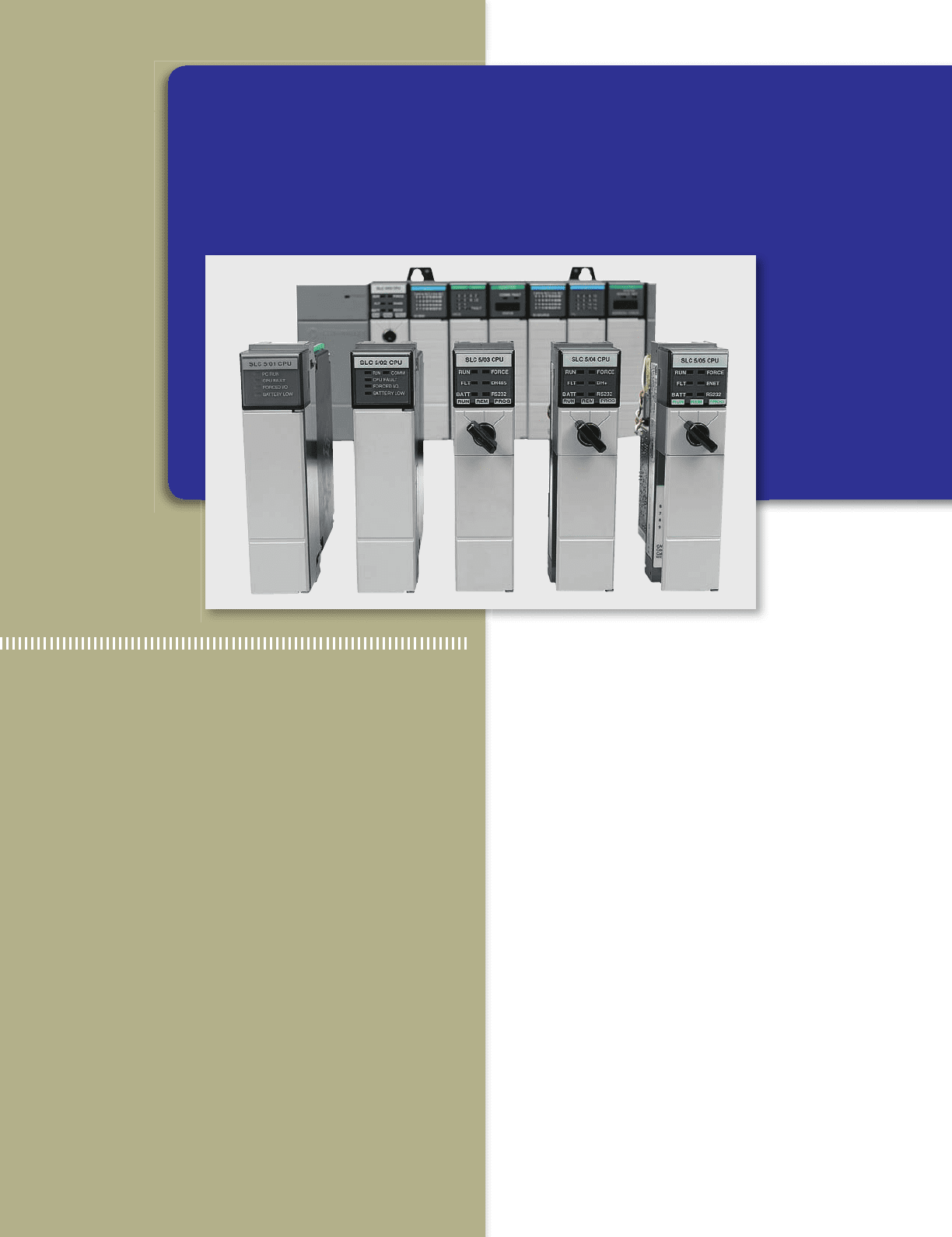
Programming Counters
Image Used with Permission of Rockwell Automation, Inc.
pet10882_ch08_149-175.indd 149pet10882_ch08_149-175.indd 149 7/23/10 10:00 PM7/23/10 10:00 PM
150 Chapter 8 Programming Counters
or program sources for counting. The two methods used
to represent a counter within a PLC’s ladder logic pro-
gram are the coil format and the block format. Figure8-4
shows a typical coil-formatted up-counter instruction.
The up-counter increments its accumulated value by 1
each time the counter rung makes a false-to-true transi-
tion. When the accumulated count equals the preset count
the counter output is energized or set to 1. Shown as part
of the instruction are the:
Counter type
Counter address
Counter preset value
Accumulated count
The counter reset instruction must be used in conjunc-
tion with the counter instruction. Up-counters are always
reset to zero. Down-counters may be reset to zero or
to some preset value. Some manufacturers include the
reset function as a part of the general counter instruc-
tion, whereas others dedicate a separate instruction for
resetting the counter. Figure8-5 shows a coil-formatted
counter instruction with a separate instruction for reset-
ting the counter. When programmed, the counter reset
coil (CTR) is given the same reference address as the
8.1 Counter Instructions
Programmed counters can serve the same function as me-
chanical counters. Figure8-1 shows the construction of a
simple mechanical counter. Every time the actuating lever
is moved over, the counter adds one number; the actuating
lever then returns automatically to its original position.
Resetting to zero is done with a pushbutton located on the
side of the unit.
Electronic counters, such as those shown in Figure8-2 ,
can count up, count down, or be combined to count up
and down. Although the majority of counters used in in-
dustry are up-counters, numerous applications require the
implementation of down-counters or of combination up/
down-counters.
All PLC manufacturers offer some form of counter
instruction as part of their instruction set. One common
counter application is keeping track of the number of items
moving past a given point as illustrated in Figure8-3 .
Counters are similar to timers except that they do not
operate on an internal clock but are dependent on external
Figure 8-1 Mechanical counter.
Reset
button
Actuating
lever
0000312
Figure 8-2 Electronic counters.
Source: Photo courtesy Omron Industrial Automation, www.ia.omron.com.
Figure 8-3 Counter application.
PLC
Figure 8-4 Coil-formatted up-counter instruction.
XXX
PR: YYY
AC: 000
Counter address
Accum
ulated
counter value
Preset counter
value
Increments
counter by 1
for each
false-to-true
transition.
Type of
counter
CTU
pet10882_ch08_149-175.indd 150pet10882_ch08_149-175.indd 150 7/23/10 10:01 PM7/23/10 10:01 PM
Programming Counters Chapter 8 151
of the input signal. The counter will either increment
or decrement whenever the count input transfers from
an off state to an on state. The counter will not operate
on the trailing edge, or on-to-off transition, of the input
condition.
Some manufacturers require the reset rung or line to be
true to reset the counter, whereas others require it to be
false to reset the counter. For this reason, it is wise tocon-
sult the PLC’s operations manual before attempting any
programming of counter circuits.
PLC counters are normally retentive; that is, whatever
count was contained in the counter at the time of a proces-
sor shutdown will be restored to the counter on power-up.
The counter may be reset, however, if the reset condition
is activated at the time of power restoration.
PLC counters can be designed to count up to a preset
value or to count down to a preset value. The up-counter
is incremented by 1 each time the rung containing the
counter is energized. The down-counter decrements by 1
each time the rung containing the counter is energized.
These rung transitions can result from events occurring
in the program, such as parts traveling past a sensor or
actuating a limit switch. The preset value of a program-
mable controller counter can be set by the operator or can
be loaded into a memory location as a result of a program
decision.
Figure8-7 illustrates the counting sequence of an up-
counter and a down-counter. The value indicated by the
counter is termed the accumulated value. The counter will
increment or decrement, depending on the type of coun-
ter, until the accumulated value of the counter is equal to
or greater than the preset value, at which time an output
will be produced. A counter reset is always provided to
cause the counter accumulated value to be reset to a pre-
determined value.
counter (CTU) that it is to reset. In this example the reset
instruction is activated whenever the CTR rung condi-
tion is true.
Figure 8-6 shows a block-formatted counter. The
instruction block indicates the type of counter (up or
down), along with the counter’s preset value and accu-
mulated or current value. The counter has two input con-
ditions associated with it, namely, the count and reset.
All PLC counters operate, or count, on the leading edge
Figure 8-5 Coil-formatted counter and reset instructions.
XXX
XXX
PR: YYY
AC: 000
Count
rung
Resets
counter
Reset
rung
Same
address
CTU
CTR
Figure 8-6 Block-formatted counter instruction.
Count
line
Input
module
Type of
counter
Preset value
Accumulated
value
Output
line
Reset
line
Figure 8-7 Counter counting sequence.
Limit
switch
Accumulated ⫽ Preset ⫽
Up-counter
Down-counter
Counter—up
ⴙ4
Counter
value
Of
f
On
Output
Parts
sensor
Accumulated ⫽ Preset ⫽
Counter—down
ⴚ5
Counter
value
Of
f
On
Output
pet10882_ch08_149-175.indd 151pet10882_ch08_149-175.indd 151 7/23/10 10:01 PM7/23/10 10:01 PM
152 Chapter 8 Programming Counters
8.2 Up-Counter
The up-counter is an output instruction whose function is
to increment its accumulated value on false-to-true transi-
tions of its instruction. It thus can be used to count false-
to-true transitions of an input instruction and then trigger
an event after a required number of counts or transitions.
The up-counter output instruction will increment by 1
each time the counted event occurs.
Figure8-8 shows the program and timing diagram for
an SLC 500 Count-Up Counter. This control application
is designed to turn the red pilot light on and the green pilot
light off after an accumulated count of 7. The operation of
the program can be summarized as follows:
• Operating pushbutton PB1 provides the off-to-on
transition pulses that are counted by the counter.
• The preset value of the counter is set for 7.
L1 L2Ladder logic programInputs Outputs
PB1 (Count)
PB1 (Count)
PB2 (Reset)
Counter done bit
Red PL
Counter done bit
Green PL
Green PL
Red PL
PB2 (Reset)
Rung 1
Rung 2
Rung 3
Rung 4
I:1/0
I:1/0
C5:1/DN
O:2/0
O:2/1
O:2/0
O:2/1
C5:1
C5:1/DN
I:1/1
I:1/1
(a)
CTU
COUNT-UP COUNTER
Counter
Preset
Accumulated
C5:1
7
0
RES
CU
DN
G
R
Figure 8-8 Simple up-counter program. (a) Program. (b) Timing diagram.
Rung 1
Rung 2
Rung 3
Rung 4
(count)
Preset
value (7)
Accumulated
value
False
True
1234567
1
2
3
4
5
67
(b)
(reset)
pet10882_ch08_149-175.indd 152pet10882_ch08_149-175.indd 152 7/23/10 10:01 PM7/23/10 10:01 PM