Petruzella F.D. Programmable Logic Controllers
Подождите немного. Документ загружается.

Developing Fundamental PLC Wiring Diagrams and Ladder Logic Programs Chapter 6 123
1. Design and draw the schematic for a conventional
hardwired relay circuit that will perform each of
the following circuit functions when a normally
closed pushbutton is pressed:
• Switch a pilot light on
• De-energize a solenoid
• Start a motor running
• Sound a horn
2. Design and draw the schematic for a conven-
tional hardwired circuit that will perform the fol-
lowing circuit functions using two break-make
pushbuttons:
• Turn on light L1 when pushbutton PB1 is pressed.
• Turn on light L2 when pushbutton PB2 is pressed.
• Electrically interlock the pushbuttons so that L1
and L2 cannot both be turned on at the same time.
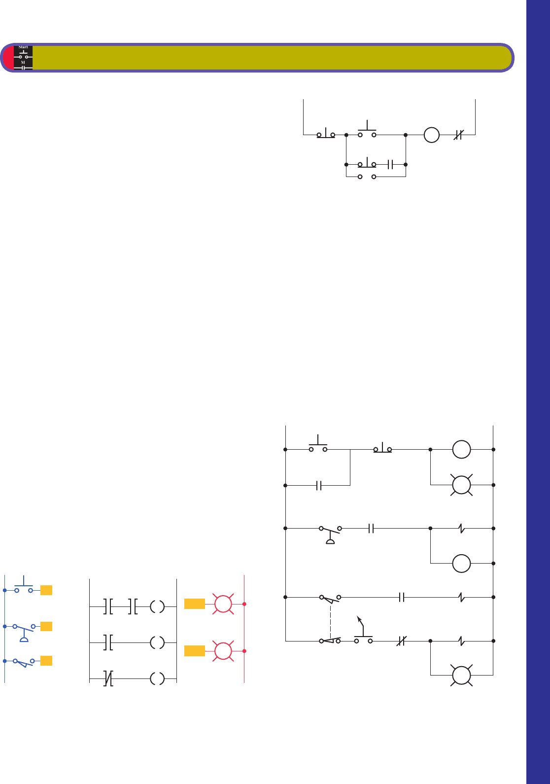
3. Study the ladder logic program in Figure 6-69 , and
answer the questions that follow:
a. Under what condition will the latch rung 1 be true?
b. Under what conditions will the unlatch rung 2 be
true?
c. Under what condition will rung 3 be true?
d. When PL1 is on, the relay is in what state
(latched or unlatched)?
e. When PL2 is on, the relay is in what state
(latched or unlatched)?
f. If AC power is removed and then restored to the
circuit, what pilot light will automatically come
on when the power is restored?
g. Assume the relay is in its latched state and all three
inputs are false. What input change(s) must occur
for the relay to switch into its unlatched state?
h. If the examine if closed instructions at addresses
I/1, I/2, and I/3 are all true, what state will the
relay remain in (latched or unlatched)?
4. Design a PLC program and prepare a typical I/O
connection diagram and ladder logic program that
will correctly execute the hardwired control circuit
in Figure 6-70 .
Assume: Stop pushbutton used is an NO type.
Run pushbutton used is an NO type.
Jog pushbutton used has one set of NO
contacts.
OL contact is hardwired.
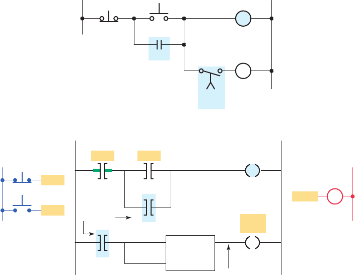
5. Design a PLC program and prepare a typical I/O
connection diagram and ladder logic program that
will correctly execute the hardwired control circuit
in Figure 6-71 .
CHAPTER 6 PROBLEMS
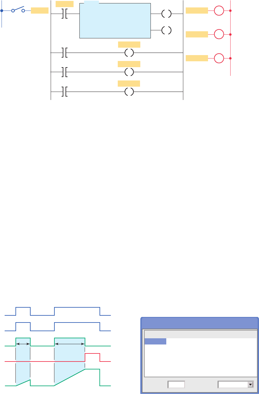
Figure 6-69 Ladder logic program for Problem 3.
I/1
L1
Inputs Ladder logic program Outputs
L2
I/2
I/3
I/1 I/2 O/9
L
I/3 O/9
U
O/9 O/10
Rung 1
Rung 2
Rung 3
PL2
PL1
O/10
O/9
Figure 6-70 Hardwired control circuit for Problem 4.
LL
Stop
Run
OL
Jog
M
21
M
Figure 6-71 Hardwired control circuit for Problem 5.
Start
CR1
SOL
CR1-2
CR1-1
PS1
LS1
SS1
CR2-2
CR2-1
CR2
SOL
SOL
LL
1
2
3
2
1
21
Stop
PB
PB
PL1
PL2
pet10882_ch06_095-124.indd 123pet10882_ch06_095-124.indd 123 7/23/10 9:22 PM7/23/10 9:22 PM

124 Chapter 6 Developing Fundamental PLC Wiring Diagrams and Ladder Logic Programs
Assume: PB1 pushbutton used is an NO type.
PB2 pushbutton used is an NC type.
PS1 pressure switch used is an NO type.
LS1 limit switch used has only one set of
NC contacts.
6. Design a PLC program and prepare a typical I/O
connection diagram and ladder logic program that
will correctly execute the hardwired control circuit
in Figure 6-72 .
Assume: PB1 pushbutton used is an NC type.
PB2 and PB3 are each wired using one set
of NO contacts.
OL contact is hardwired.
7. Design a PLC program and prepare a typical I/O
connection diagram and ladder logic program for
the following motor control speci cations:
• A motor must be started and stopped from any
one of three start/stop pushbutton stations.
• Each start/stop station contains one NO start
pushbutton and one NC stop pushbutton.
• Motor OL contacts are to be hardwired.
8. Design a PLC program and prepare a typical I/O
connection diagram and ladder logic program for
the following motor control speci cations:
• Three starters are to be wired so that each starter
is operated from its own start/stop pushbutton
station.
• A master stop station is to be included that will
trip out all starters when pushed.
• Overload relay contacts are to be programmed so
that an overload on any one of the starters will
automatically drop all of the starters.
• All pushbuttons are to be wired using one set of
NO contacts.
9. A temperature control system consists of four
thermostats controlling three heating units. The
thermostat contacts are set to close at 50°, 60°,
70°, and 80°F, respectively. The PLC ladder logic
program is to be designed so that at a temperature
below 50°F, three heaters are to be ON. Between
50° to 60°F, two heaters are to be ON. For 60° to
70°F, one heater is to be ON. Above 80°F, there is a
safety shutoff for all three heaters in case one stays
on because of a malfunction. A master switch is to
be used to turn the system ON and OFF. Prepare a
typical PLC program for this control process.
10. A pump is to be used to ll two storage tanks. The
pump is manually started by the operator from a
start/stop station. When the rst tank is full, the
control logic must be able to automatically stop
ow to the rst tank and direct ow to the second
tank through the use of sensors and electric sole-
noid valves. When the second tank is full, the pump
must shut down automatically. Indicator lamps are
to be included to signal when each tank is full.
a. Draw a sketch of the process.
b. Prepare a typical PLC program for this control
process.
11. Write the optimum ladder logic rung for each of the
following scenarios, and arrange the instructions
for optimum performance:
a. If limit switches LS1 or LS2 or LS3 are on, or if
LS5 and LS7 are on, turn on; otherwise, turn off.
(Commonly, if LS5 and LS7 are on, the other
conditions rarely occur.)
b. Turn on an output when switches SW6, SW7,
and SW8 are all on, or when SW55 is on.
(SW55 is an indication of an alarm state, so it
is rarely on; SW7 is on most often, then SW8,
then SW6.)
Figure 6-72 Hardwired control circuit for Problem 6.
Stop
PB
REV
FWD
PB
PB
R-1
F
OL
PL1
F-2
R-2
PL2
LL
F-1
R
2
3
21
1
pet10882_ch06_095-124.indd 124pet10882_ch06_095-124.indd 124 7/23/10 9:22 PM7/23/10 9:22 PM
125
7
Programming Timers
The most commonly used PLC instruction, after
coils and contacts, is the timer. This chapter
deals with how timers time intervals and the way
in which they can control outputs. We discuss
the basic PLC on-delay timer function, as well as
other timing functions derived from it, and typical
industrial timing tasks.
Chapter Objectives
After completing this chapter, you will be able to:
7.1 Describe the operation of pneumatic on-delay and
off-delay timers
7.2 Describe PLC timer instruction and differentiate
between a nonretentive and retentive timer
7.3 Convert fundamental timer relay schematic diagrams
to PLC ladder logic programs
7.4 Analyze and interpret typical PLC timer ladder logic
programs
7.5 Program the control of outputs using the timer
instruction control bits
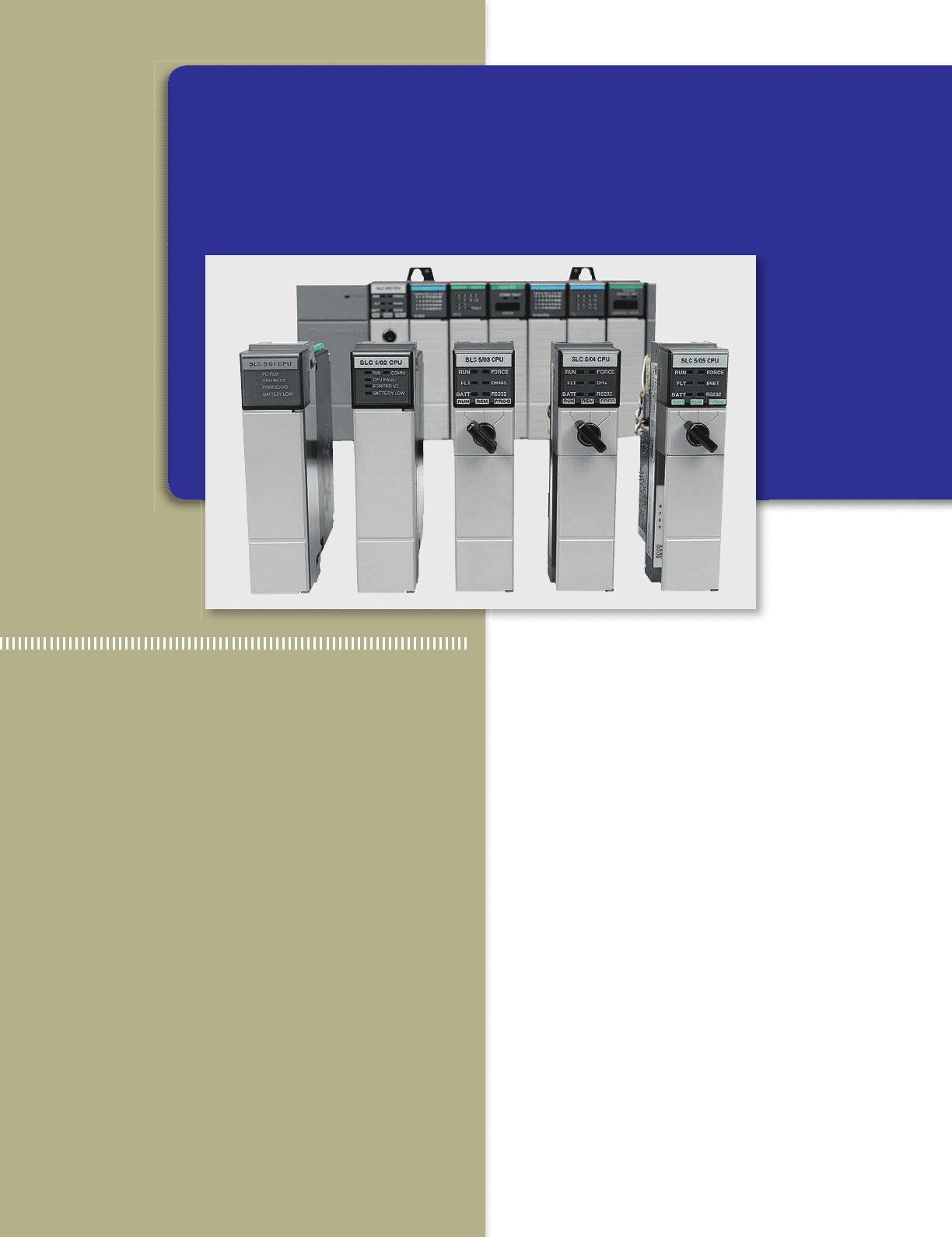
Image Used with Permission of Rockwell Automation, Inc.
pet10882_ch07_125-148.indd 125pet10882_ch07_125-148.indd 125 7/23/10 9:35 PM7/23/10 9:35 PM
126 Chapter 7 Programming Timers
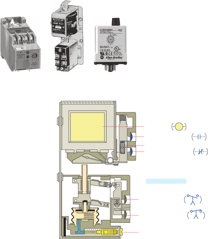
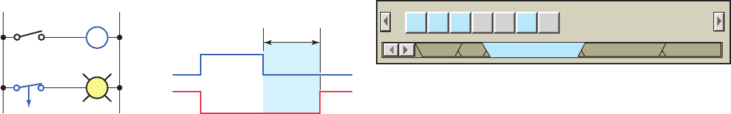
Figure7-2 shows the construction of an on-delay pneu-
matic (air) timer. The time-delay function depends on
the transfer of air through a restricted ori ce. The time-
delay period is adjusted by positioning the needle valve
to vary the amount of ori ce restriction. When the coil
is energized, the timed contacts are delayed from open-
ing or closing. However, when the coil is de- energized,
the timed contacts return instantaneously to their normal
state. This particular pneumatic timer has instantaneous
contacts in addition to timed contacts. The instantaneous
contacts change state as soon as the timer coil is pow-
ered while the delayed contacts change state at the end
of the time delay. Instantaneous contacts are often used
as holding or sealing contacts in a control circuit.
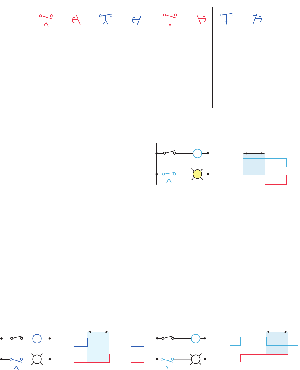
Mechanical timing relays provide time delay through
two arrangements. The rst arrangement, on delay, pro-
vides time delay when the relay coil is energized. The
second arrangement, off delay, provides time delay when
the relay coil is de-energized. Figure 7-3 illustrates the
different relay symbols used for timed contacts.
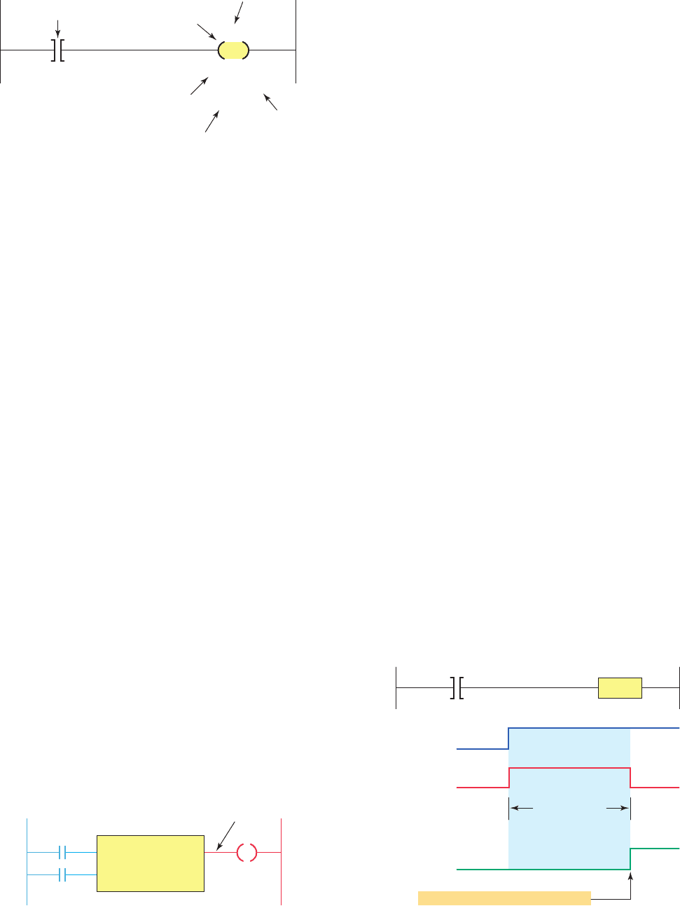
The on-delay timer is sometimes referred to as DOE,
which stands for delay on energize. The time delay of the
contacts begins once the timer is switched on; hence the term
on-delay timing. Figure7-4 shows an on-delay timer circuit
that uses a normally open, timed closed (NOTC) contact.
The operation of the circuit can be summarized as follows:
• With S1 initially open, TD coil is de-energized so
TD1 contacts are open and light L1 will be off.
7.1 Mechanical Timing Relays
There are very few industrial control systems that do not
need at least one or two timed functions. Mechanical tim-
ing relays are used to delay the opening or closing of con-
tacts for circuit control. The operation of a mechanical
timing relay is similar to that of a control relay, except that
certain of its contacts are designed to operate at a preset
time interval, after the coil is energized or de-energized.
Typical types of mechanical and electronic timing relays
are shown in Figure7-1 . Timers allow a multitude of op-
erations in a control circuit to be automatically started and
stopped at different time intervals.
Figure 7-1 Timing relays.
Source: Image Used with Permission of Rockwell Automation, Inc.
Solid-state timing relay Plug-in timing relayPneumatic timing relay
Figure 7-2 Pneumatic on-delay timer.
Time adjustment
Normally closed terminals
Normally closed terminals
Instantaneous contacts
Normally open terminals
Time control contacts
Normally open terminals
Operating coil
pet10882_ch07_125-148.indd 126pet10882_ch07_125-148.indd 126 7/23/10 9:35 PM7/23/10 9:35 PM
Programming Timers Chapter 7 127
Figure7-6 shows an off-delay timer circuit that uses a
normally open, timed open (NOTO) contact. The opera-
tion of the circuit can be summarized as follows:
• With S1 initially open, TD coil is de-energized so
TD1 contacts are open and light L1 will be off.
• When S1 is closed, TD coil is energized and TD1
contacts close instantly to switch light L1 on.
• When S1 is opened, TD coil is de-energized and the
timing period starts.
• After the 10 s time-delay period has elapsed,
TD1contacts open to switch the light off.
• When S1 is closed TD coil is energized and the tim-
ing period starts. TD1 contacts are delayed from
closing so L1 remains off.
• After the 10 s time-delay period has elapsed, TD1
contacts close and L1 is switched on.
• When S1 is opened, TD coil is de-energized and
TD1 contacts open instantly to switch L1 off.
Figure7-5 shows an on-delay timer circuit that uses a
normally closed, timed open (NCTO) contact. The opera-
tion of the circuit can be summarized as follows:
• With S1 initially open, TD coil is de-energized
so TD1 contacts are closed and light L1 will
be on.
• When S1 is closed, TD coil is energized and the
timing period starts. TD1 contacts are delayed from
opening so L1 remains on.
• After the 10 s time-delay period has elapsed, TD1
contacts open and L1 is switched off.
• When S1 is opened, TD coil is de-energized and
TD1 contacts close instantly to switch L1 on.
Figure 7-3 Timed contact symbols.
On-delay symbols
Normally open, timed
closed contact (NOTC).
Contact is open when
relay coil is de-energized.
When relay is energized,
there is a time delay in
closing.
Normally closed, timed
open contact (NCTO).
Contact is closed when
relay coil is de-energized.
When relay is energized,
there is a time delay in
opening.
or
Normally closed, timed
closed contact (NCTC).
Contact is normally
closed when relay coil
is de-energized.
When relay coil is
energized, contact
opens instantly.
When relay coil is
de-energized, there is
a time delay before the
contact closes.
Off-delay symbols
Normally open, timed
open contact (NOTO).
Contact is normally
open when relay coil
is de-energized.
When relay coil is
energized, contact
closes instantly.
When relay coil is
de-energized, there is
a time delay before the
contact opens.
or
or
or
Figure 7-4 On-delay timer circuit that uses a normally
open, timed closed (NOTC) contact.
L2L1
TD1
L1
S1
10 s
Timing diagram
Input
(S1)
Output
(L1)
Off
On
TD
Figure 7-5 On-delay timer circuit that uses a normally
closed, timed open (NCTO) contact.
L1
TD1
L1
S1
TD
10 s
10 s
Timing diag
ram
Input
(S1)
Output
(L1)
Off
On
L2
Figure 7-6 Off-delay timer circuit that uses a normally
open, timed open (NOTO) contact.
L2L1
TD1
L1
S1
TD
10 s
Timing diagram
Input
(S1)
Output
(L1)
10 s
Off
On
pet10882_ch07_125-148.indd 127pet10882_ch07_125-148.indd 127 7/23/10 9:35 PM7/23/10 9:35 PM
128 Chapter 7 Programming Timers
RTO (Retentive Timer On) —Counts time-based
intervals when the instruction is true and retains the
accumulated value when the instruction goes false or
when power cycle occurs.
RES (Reset) —Resets a retentive timer’s accumulated
value to zero.
Several quantities are associated with the timer
instruction:
• The preset time represents the time duration for
the timing circuit. For example, if a time delay
of10 s is required, the timer will have a preset of
10 s.
• The accumulated time represents the amount of
time that has elapsed from the moment the timing
coil became energized.
• Every timer has a time base. Once the timing rung
has continuity, the timer counts in time-based in-
tervals and times until the preset value and accu-
mulated value are equal or, depending on the type
of controller, up to the maximum time interval of
the timer. The intervals that the timers time out at
are generally referred to as the time bases of the
timer. Timers can be programmed with several dif-
ferent time bases: 1 s, 0.1 s, and 0.01 s are typical
time bases. If a programmer entered 0.1 for the time
base and 50 for the number of delay increments, the
timer would have a 5-s delay (50 3 0.1 s 5 5 s).
The smaller the time base selected, the better the ac-
curacy of the timer.
Although each manufacturer may represent timers
differently on the ladder logic program, most timers
operate in a similar manner. One of the rst methods used
depicts the timer instruction as a relay coil similar to that
of a mechanical timing relay. Figure 7-9 shows a coil-
formatted timer instruction. Its operation can be summa-
rized as follows:
• The timer is assigned an address and is identi ed as
a timer.
• Also included as part of the timer instruction is the
time base of the timer, the timer’s preset value or
time-delay period, and the accumulated value or
current time-delay period for the timer.
Figure7-7 shows an off-delay timer circuit that uses a
normally closed, timed closed (NCTC) contact. The op-
eration of the circuit can be summarized as follows:
• With S1 initially open, TD coil is de-energized so
TD1 contacts are closed and light L1 will be on.
• When S1 is closed, TD coil is energized and TD1
contacts open instantly to switch light L1 off.
• When S1 is opened, TD coil is de-energized and the
timing period starts. TD1 contacts are delayed from
closing so L1 remains off.
• After the 10 s time-delay period has elapsed, TD1
contacts close to switch the light on.
7. 2 Timer Instructions
PLC timers are instructions that provide the same func-
tions as on-delay and off-delay mechanical and electronic
timing relays. PLC timers offer several advantages over
their mechanical and electronic counterparts. These in-
clude the fact that:
• Time settings can be easily changed.
• The number of them used in a circuit can be in-
creased or decreased through the use of program-
ming changes rather than wiring changes.
• Timer accuracy and repeatability are extremely high
because its time delays are generated in the PLC
processor.
In general, there are three different PLC timer types: the
on-delay timer (TON), off-delay timer (TOF), and retentive
timer on (RTO). The most common is the on-delay timer,
which is the basic function. There are also many other tim-
ing con gurations, all of which can be derived from one or
more of the basic time-delay functions. Figure7-8 shows
the timer selection toolbar for the Allen-Bradley SLC 500
PLC and its associated RSLogix software. These timer
commands can be summarized as follows:
TON (Timer On Delay) —Counts time-based inter-
vals when the instruction is true.
TOF (Timer Off Delay) —Counts time-based inter-
vals when the instruction is false.
Figure 7-7 Off-delay timer circuit that uses a normally
closed, timed closed (NCTC) contact.
L2L1
TD1
L1
S1
TD
10 s
Timing diagram
10 s
Input
Output
Off
On
Figure 7-8 Timer selection toolbar.
TON TOF RTO CTU CTD RES
HSC
User Bit Timer/Counter Input/Output Compare
HSC
pet10882_ch07_125-148.indd 128pet10882_ch07_125-148.indd 128 7/23/10 9:35 PM7/23/10 9:35 PM
Programming Timers Chapter 7 129
• The timer instruction block contains information
pertaining to the operation of the timer, including
the preset time, the time base of the timer, and the
current or accumulated time.
• All block-formatted timers provide at least one out-
put signal from the timer. The timer continuously
compares its current time with its preset time, and
its output is false (logic 0) as long as the current
time is less than the preset time. When the current
time equals the preset time, the output changes to
true (logic 1).
7. 3 On-Delay Timer Instruction
Most timers are output instructions that are conditioned
by input instructions. An on-delay timer is used when
you want to program a time delay before an instruction
becomes true. Figure7-11 illustrates the principle of op-
eration of an on-delay timer. Its operation can be summa-
rized as follows:
• The on-delay timer operates such that when the
rung containing the timer is true, the timer time-out
period commences.
• At the end of the timer time-out period, an output is
made true.
• The timed output becomes true sometime after the
timer rung becomes true; hence, the timer is said to
have an on-delay.
• The length of the time delay can be adjusted by
changing the preset value.
• In addition, some PLCs allow the option of chang-
ing the time base, or resolution, of the timer. As the
time base you select becomes smaller, the accuracy
of the timer increases.
• When the timer rung has logic continuity, the timer
begins counting time-based intervals and times until
the accumulated value equals the preset value.
• When the accumulated time equals the preset time,
the output is energized and the timed output contact
associated with the output is closed. The timed con-
tact can be used as many times as you wish through-
out the program as an NO or NC contact.
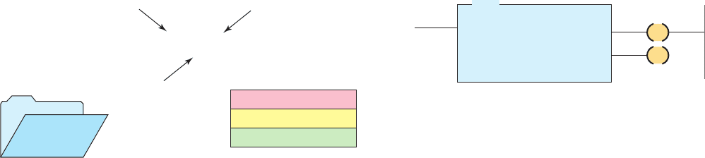
Timers are most often represented by boxes in ladder
logic. Figure7-10 illustrates a generic block format for a
retentive timer that requires two input lines. Its operation
can be summarized as follows:
• The timer block has two input conditions associated
with it, namely, the control and reset.
• The control line controls the actual timing operation
of the timer. Whenever this line is true or power is
supplied to this input, the timer will time. Removal
of power from the control line input halts the further
timing of the timer.
• The reset line resets the timer’s accumulated value
to zero.
• Some manufacturers require that both the control and
reset lines be true for the timer to time; removal of
power from the reset input resets the timer to zero.
• Other manufacturers’ PLCs require power ow for
the control input only and no power ow on the
reset input for the timer to operate. For this type of
timer operation, the timer is reset whenever the reset
input is true.
Figure 7-9 Coil-formatted timer instruction.
TON
XXX
Timer address
T
ype of timer
Determines
rung continuity
Timer preset value
Time accumulated
or current value
YYY
0.1 s
000
PR:
TB:
AC
:
Time
base of
timer
Figure 7-10 Block-formatted timer instruction.
Preset time
Time base
Accumulated time
Control line
Reset line
Output line
Figure 7-11 Principle of operation of an on-delay timer.
Preset value = accumulated value
Timed output bit
Timed period
Rung condition
Off (logic 0)
False
False
On (logic 1)
Tr ue
Tr ue
Timer
Input
On-delay
timed duration
pet10882_ch07_125-148.indd 129pet10882_ch07_125-148.indd 129 7/23/10 9:35 PM7/23/10 9:35 PM
130 Chapter 7 Programming Timers
Figure7-13 shows an example of the on-delay timer
instruction used as part of the Allen-Bradley PLC-5 and
SLC 500 controller instruction sets. The information to be
entered includes:
Timer number —This number must come from the
timer le. In the example shown, the timer number is
T4:0, which represents timer le 4, timer 0 in that le.
The timer address must be unique for this timer and
may not be used for any other timer.
Time base —The time base (which is always ex-
pressed in seconds) may be either 1.0 s or 0.01 s. In
the example shown, the time base is 1.0 s.
Preset value —In the example shown, the preset value
is 15. The timer preset value can range from 0 through
32,767.
Accumulated value —In the example shown, the ac-
cumulated value is 0. The timer’s accumulated value
normally is entered as 0, although it is possible to
enter a value from 0 through 32,767. Regardless of the
value that is preloaded, the timer value will become 0
whenever the timer is reset.
The on-delay timer (TON) is the most commonly used
timer. Figure7-14 shows a PLC program that uses an on-
delay timer. The operation of the program can be sum-
marized as follows:
• The timer is activated by input switch A.
• The preset time for this timer is 10 s, at which time
output D will be energized.
• When input switch is A is closed, the timer becomes
true and the timer begins counting and counts until
the accumulated time equals the preset value; the
output D is then energized.
• If the switch is opened before the timer is timed out,
the accumulated time is automatically reset to 0.
• This timer con guration is termed nonretentive be-
cause any loss of continuity to the timer causes the
timer instruction to reset.
• This timing operation is that of an on-delay timer
because output D is switched on 10 s after the
switch has been actuated from the off to the on
position.
The Allen-Bradley SLC 500 timer le is le 4 ( Fig-
ure7-12 ). Each timer is composed of three 16-bit words,
collectively called a timer element. There can be up to
256 timer elements. Addresses for timer le 4, timer ele-
ment number 2 (T4:2), are listed below.
T4 5 timer le 4
:2 5 timer element number 2 (0–255 timer elements
per le)
T4:2/DN is the address for the done bit of the timer.
T4:2/TT is the address for the timer-timing bit of the
timer.
T4:2/EN is the address for the enable bit of the timer.
The control word uses the following three control bits:
Enable (EN) bit —The enable bit is true (has a status
of 1) whenever the timer instruction is true. When the
timer instruction is false, the enable bit is false (has a
status of 0).
Timer-timing (TT) bit —The timer-timing bit is true
whenever the accumulated value of the timer is chang-
ing, which means the timer is timing. When the timer
is not timing, the accumulated value is not changing,
so the timer-timing bit is false.
Done (DN) bit —The done bit changes state whenever
the accumulated value reaches the preset value. Its
state depends on the type of timer being used.
The preset value (PRE) word is the set point of the timer,
that is, the value up to which the timer will time. The preset
word has a range of 0 through 32,767 and is stored in binary
form. The preset will not store a negative number.
The accumulated value (ACC) word is the value that in-
crements as the timer is timing. The accumulated value will
stop incrementing when its value reaches the preset value.
The timer instruction also requires that you enter a time
base, which is either 1.0 s or 0.01 s. The actual preset time
interval is the time base multiplied by the value stored
in the timer’s preset word. The actual accumulated time
interval is the time base multiplied by the value stored in
the timer’s accumulated word.
Figure 7-12 SLC 500 timer fi le.
File number
Timers
4
File type
Timer number
EN TT DNWord 0
T4:2
15 14 13
Preset valueWord 1
Accumulated valueWord 2
T4:0
1.0
15
0
TON
TIMER ON DELAY
Timer
Time base
Preset
Accumulated
EN
DN
Figure 7-13 On-delay timer instruction.
pet10882_ch07_125-148.indd 130pet10882_ch07_125-148.indd 130 7/23/10 9:35 PM7/23/10 9:35 PM
Programming Timers Chapter 7 131
The timer uses three words per element. Each element
consists of a control word, a preset word, and an accumu-
lated word. Each word has 16 bits, which are numbered
from 0 to 15. When addressing to the bit level, the address
always refers to the bit within the word:
EN 5 Bit 15 enable
TT 5 Bit 14 timer timing
DN 5 Bit 13 done
Timers may or may not have an instantaneous output
(also known as the enable bit) signal associated with
them. If an instantaneous output signal is required from
a timer and it is not provided as part of the timer in-
struction, an equivalent instantaneous contact instruc-
tion can be programmed using an internally referenced
relay coil. Figure7-17 shows an application of this tech-
nique. The operation of the program can be summarized
as follows:
• According to the hardwired relay circuit diagram,
coil M is to be energized 5 s after the start pushbut-
ton is pressed.
Figure 7-15 shows the timing diagram for the on-
delay timer’s control bits. The sequence of operation is
as follows:
• The rst true period of the timer rung shows the
timer timing to 4 s and then going false.
• The timer resets, and both the timer-timing bit and
the enable bit go false. The accumulated value also
resets to 0.
• For the second true period input A remains true in
excess of 10 s.
• When the accumulated value reaches 10 s, the done
bit (DN) goes from false to true and the timer-
timing bit (TT) goes from true to false.
• When input A goes false, the timer instruction goes
false and also resets, at which time the control bits
are all reset and the accumulated value resets to 0.
The timer table for an Allen-Bradley SLC 500 is shown
in Figure7-16 . Addressing is done at three different lev-
els: the element level, the word level, and the bit level.
L1
Input A
Input A
T4:0
T4:0
T4:0
EN
TT
DN
Output C
TON
TIMER ON DELAY
Timer T4:0
Time base 1.0
Preset 10
Accumulated 0
L2
Output B
Output C
Output D
Output B
Output D
Ladder logic program OutputsInput
G
R
Y
EN
DN
Figure 7-14 PLC on-delay timer program.
Figure 7-15 Timing diagram for an on-delay timer.
Input condition A
Timer-enable bit
Timer-done bit
On
On
On
On
Off
Off
Off
Off
Timer
accumulated
value
0
4 s
10 s
Timer-timing bit
Timer Table
/EN /TT /DN .PRE .ACC
T4:0 0 0 0 10 0
T4:1 0 0 0 0 0
T4:2 0 0 0 0 0
T4:3 0 0 0 0 0
T4:4 0 0 0 0 0
T4:5 0 0 0 0 0
Address
T4:0
Table:
T4: Timer
Figure 7-16 SLC 500 timer table.
pet10882_ch07_125-148.indd 131pet10882_ch07_125-148.indd 131 7/23/10 9:35 PM7/23/10 9:35 PM
132 Chapter 7 Programming Timers
• The logic on the last rung is the same as the timer-
timing bit and as such can be used with timers that
do not have a timer-timing output.
Timers are often used as part of automatic sequential
control systems. Figure7-19 shows how a series of mo-
tors can be started automatically with only one start/stop
control station. The operation of the circuit can be sum-
marized as follows:
• According to the relay ladder schematic, lube-oil
pump motor starter coil M1 is energized when the
start pushbutton PB2 is momentarily actuated.
• As a result, M1-1 control contact closes to seal in
M1, and the lube-oil pump motor starts.
• When the lube-oil pump builds up suf cient oil
pressure, the lube-oil pressure switch PS1 closes.
• This in turn energizes coil M2 to start the main
drive motor and energizes coil TD to begin the time-
delay period.
• After the preset time-delay period of 15 s, TD-1
contact closes to energize coil M3 and start the feed
motor.
• The ladder logic program shows how an equivalent
circuit could be programmed using a PLC.
• Contact TD-1 is the instantaneous contact, and con-
tact TD-2 is the timed contact.
• The ladder logic program shows that a contact in-
struction referenced to an internal relay is now used
to operate the timer.
• The instantaneous contact is referenced to the in-
ternal relay coil, whereas the time-delay contact is
referenced to the timer output coil.
Figure7-18 shows an application for an on-delay timer
that uses an NCTO contact. This circuit is used as a warn-
ing signal when moving equipment, such as a conveyor
motor, is about to be started. The operation of the circuit
can be summarized as follows:
• According to the hardwired relay circuit diagram,
coil CR is energized when the start pushbutton PB1
is momentarily actuated.
• As a result, contact CR-1 closes to seal in CR coil,
contact CR-2 closes to energize timer coil TD,
andcontact CR-3 closes to sound the horn.
• After a 10-s time-delay period, timer contact TD-1
opens to automatically switch the horn off.
• The ladder logic program shows how an equivalent
circuit could be programmed using a PLC.
Internal
relay
Output line
Motor
M
Internal
relay
Ladder logic program
Timer
PR: 5
TB: 1 s
L1
Inputs
L2
Output
Motor
Start
Start
M
Stop
Stop
Hardwired relay circuit
L2
L1
Stop
Start
TD-1
TD-2
(5 s)
M
TD
Figure 7-17 Instantaneous contact instruction can be programmed using an
internally referenced relay coil.
pet10882_ch07_125-148.indd 132pet10882_ch07_125-148.indd 132 7/23/10 9:35 PM7/23/10 9:35 PM