Petruzella F.D. Programmable Logic Controllers
Подождите немного. Документ загружается.

Programming Counters Chapter 8 153
• Each false-to-true transition of rung 1 increases the
counter’s accumulated value by 1.
• After 7 pulses, or counts, when the preset counter
value equals the accumulated counter value, output
DN is energized.
• As a result, rung 2 becomes true and energizes
output O:2/0 to switch the red pilot light on.
• At the same time, rung 3 becomes false and de-
energizes output O:2/1 to switch the green pilot
light off.
• The counter is reset by closing pushbutton PB2,
which makes rung 4 true and resets the accumulated
count to zero.
• Counting can resume when rung 4 goes false again.
The Allen-Bradley SLC 500 counter le is le 5 ( Fig-
ure8-9 ). Each counter is composed of three 16-bit words,
collectively called a counter element. These three data
words are the control word, preset word, and accumulated
word. Each of the three data words shares the same base
address, which is the address of the counter itself. There
can be up to 256 counter elements. Addresses for counter
le 5, counter element 3 (C5:3), are listed below.
C5 5 counter le 5
:3 5 counter element 3 (0–255 counter elements per
le)
C5:3/DN is the address for the done bit of the counter.
C5:3/CU is the address for the count-up enable bit of
the counter.
C5:3/CD is the address for the count-down enable bit
of the counter.
C5:3/OV is the address for the over ow bit of the
counter.
C5:3/UN is the address for the under ow bit of the
counter.
C5:3/UA is the address for the update accumulator bit
of the counter.
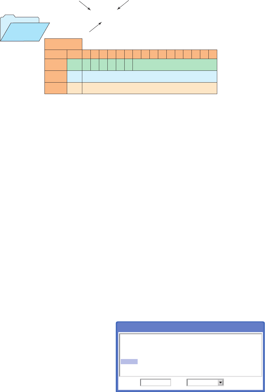
Figure 8-10 shows the counter table for the Allen-
Bradley SLC 500 controller. The control word uses status
control bits consisting of the following:
Count-Up (CU) Enable Bit —The count-up en-
able bit is used with the count-up counter and is true
whenever the count-up counter instruction is true. If
the count-up counter instruction is false, the CU bit
is false.
Count-Down (CD) Enable Bit —The count-down
enable bit is used with the count-down counter and is
true whenever the count-down counter instruction is
true. If the count-down counter instruction is false, the
CD bit is false.
Done (DN) Bit —The done bit is true whenever the
accumulated value is equal to or greater than the pre-
set value of the counter, for either the count-up or the
count-down counter.
Over ow (OV) Bit —The over ow bit is true when-
ever the counter counts past its maximum value,
which is 32,767. On the next count, the counter will
wrap around to 32,768 and will continue counting
Figure 8-9 SLC 500 counter fi le.
Counter address
C5:3 Bit 15 14 13 12 11 10 09 08 07 06 05 04 03 02 01 00
Word
0
Word
1
Word
2
C5:3.0 CU CD DN OV
UN UA Internal use (not addressable)
C5:3.1 Preset value
C5:3.2 Accumulated value
File number
Counters
5
File type
Counter number
C5:3
Figure 8-10 SLC 500 counter table.
Counter Table
C5:0
C5:1
C5:2
C5:3
C5:4
C5:5
/CU
0
0
0
0
0
0
/CD
0
0
0
0
0
0
/DN
0
0
0
0
0
0
/OV
0
0
0
0
0
0
/UN
0
0
0
0
0
0
/UA
0
0
0
0
0
0
.PRE
0
0
0
50
0
0
.ACC
0
0
0
0
0
0
C5: Counter
Ta b le :Address C5:3
pet10882_ch08_149-175.indd 153pet10882_ch08_149-175.indd 153 7/23/10 10:01 PM7/23/10 10:01 PM
154 Chapter 8 Programming Counters
from there toward 0 on successive false-to-true transi-
tions of the count-up counter.
Under ow (UN) Bit —The under ow bit will go true
when the counter counts below 32,768. The counter
will wrap around to 132,767 and continue counting
down toward 0 on successive false-to-true rung transi-
tions of the count-down counter.
Update Accumulator (UA) Bit —The update accu-
mulator bit is used only in conjunction with an exter-
nal HSC (high-speed counter).
The preset value (PRE) word speci es the value that
the counter must count to before it changes the state of the
done bit. The preset value is the set point of the counter
and ranges from 232,768 through 132,767. The number
is stored in binary form, with any negative numbers being
stored in 2’s complement binary.
The accumulated value (ACC) word is the current count
based on the number of times the rung goes from false
to true. The accumulated value either increments with a
false-to-true transition of the count-up counter instruc-
tion or decrements with a false-to-true transition of the
count-down counter instruction. It has the same range as
the preset: 232,768 through 132,767. The accumulated
value will continue to count past the preset value instead
of stopping at the preset like a timer does.
Figure8-11 shows an example of the count-up coun-
ter and its status bits used in the SLC 500 controller
instruction set. The address for counters begins at C5:0
and continues through C5:255. The information to be en-
tered includes:
Counter Number —This number must come from the
counter le. In the example shown, the counter num-
ber is C5:0, which represents counter le 5, counter 0
in that le. The address for this counter should not be
used for any other count-up counter.
Preset Value —The preset value can range from
232,768 to 132,767. In the example shown, the pre-
set value is 10.
Accumulated Value —The accumulated value can
also range from 232,768 through 132,767. Typi-
cally, as in this example, the value entered in the
accumulated word is 0. Regardless of what value is
entered, the reset instruction will reset the accumu-
lated value to 0.
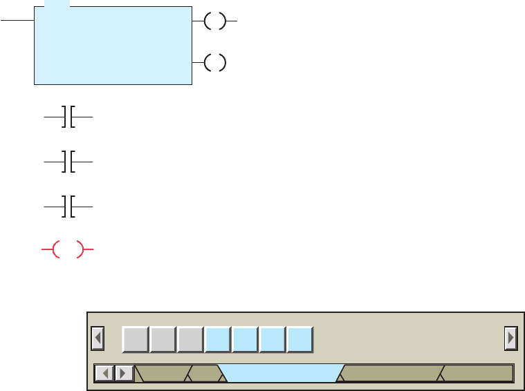
Figure 8-12 shows the timer/counter menu tab from
the RSLogix toolbar. Several timer and counter instruc-
tions appear when this tab is selected. The rst three are
timer instructions that are covered in Chapter 7. The next
two instructions from the left are the up-counter (CTU)
and down-counter (CTD) instructions. To the right of the
CTU and CTD instructions is the reset (RES) instruction,
which is used by both counters and timers. The counter
commands can be summarized as follows:
CTU (Count-Up) —Increments the accumulated
value at each false-to-true transition and retains
the accumulated value when an off/on power cycle
occurs.
CTD (Count-Down) —Decrements the accumu-
lated value at each false-to-true transition and retains
the accumulated value when an on/off power cycle
occurs.
HSC (High-Speed Counter) —Counts high-speed
pulses from a high-speed input.
Figure8-13 shows a PLC counter program used to stop
a motor from running after 10 operations. The operation
of the program can be summarized as follows:
• Up-counter C5:0 counts the number of off/on opera-
tions of the motor.
• The preset value of the counter is set to 10.
Figure 8-11 Count-up counter instruction.
CTU
COUNT-UP COUNTER
Counter
Preset
Accumulated
C5:0
10
0
C5:0/CU
Counter enable bit
C5:0/DN
Counter done bit
C5:0/OV
Overflow status bit
C5:0
The reset instruction resets
the counter's accumulated
value back to zero.
CU
DN
RES
Figure 8-12 Counter selection toolbar.
TON TOF RTO CTU CTD RES
User Bit Timer/Counter Input/Output Compare
HSC
pet10882_ch08_149-175.indd 154pet10882_ch08_149-175.indd 154 7/23/10 10:01 PM7/23/10 10:01 PM
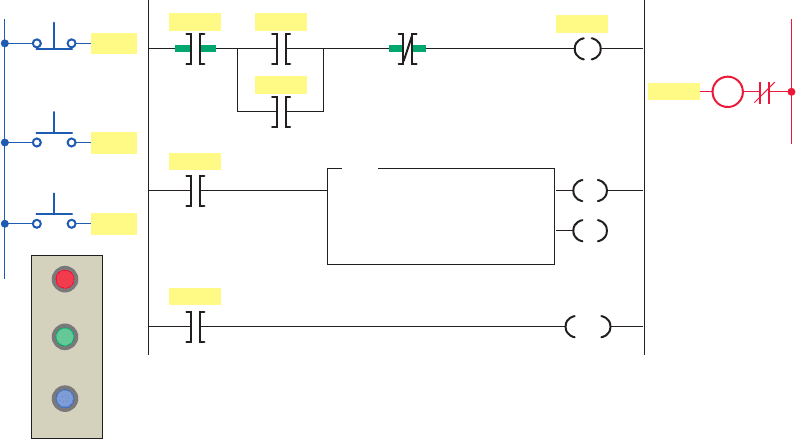
Programming Counters Chapter 8 155
• A counter done bit examine-off instruction is
programmed in series with the motor output
instruction.
• A motor output examine-on instruction is used to
increment the accumulated value of the counter for
each off/on operation.
• After the count of 10 is reached the counter done
bit examine-off instruction goes false preventing the
motor from being started.
• Closure of the reset pushbutton resets the accumu-
lated count to zero.
Figure 8-14 shows a PLC can-counting program that
uses three up-counters. The operation of the program can
be summarized as follows:
• Counter C5:2 counts the total number of cans com-
ing off an assembly line for nal packaging.
• Each package must contain 10 parts.
• When 10 cans are detected, counter C5:1 sets bit
B3/1 to initiate the box closing sequence.
• Counter C5:3 counts the total number of packages
lled in a day. (The maximum number of packages
per day is 300.)
• A pushbutton is used to restart the total part and
package count from zero daily.
One-Shot Instruction
Figure8-15 shows the program for a one-shot,
or tran-
sitional, contact circuit that is often used to automati-
cally clear or reset a counter. The program is designed
to generate an output pulse that, when triggered, goes on
for the duration of one program scan and then goes off.
The one-shot can be triggered from a momentary signal
or from a signal that comes on and stays on for some time.
Whichever signal is used, the one-shot is triggered by the
leading-edge (off-to-on) transition of the input signal. It
stays on for one scan and goes off. It stays off until the
trigger goes off, and then comes on again. The one-shot is
perfect for resetting both counters and timers since it stays
on for one scan only.
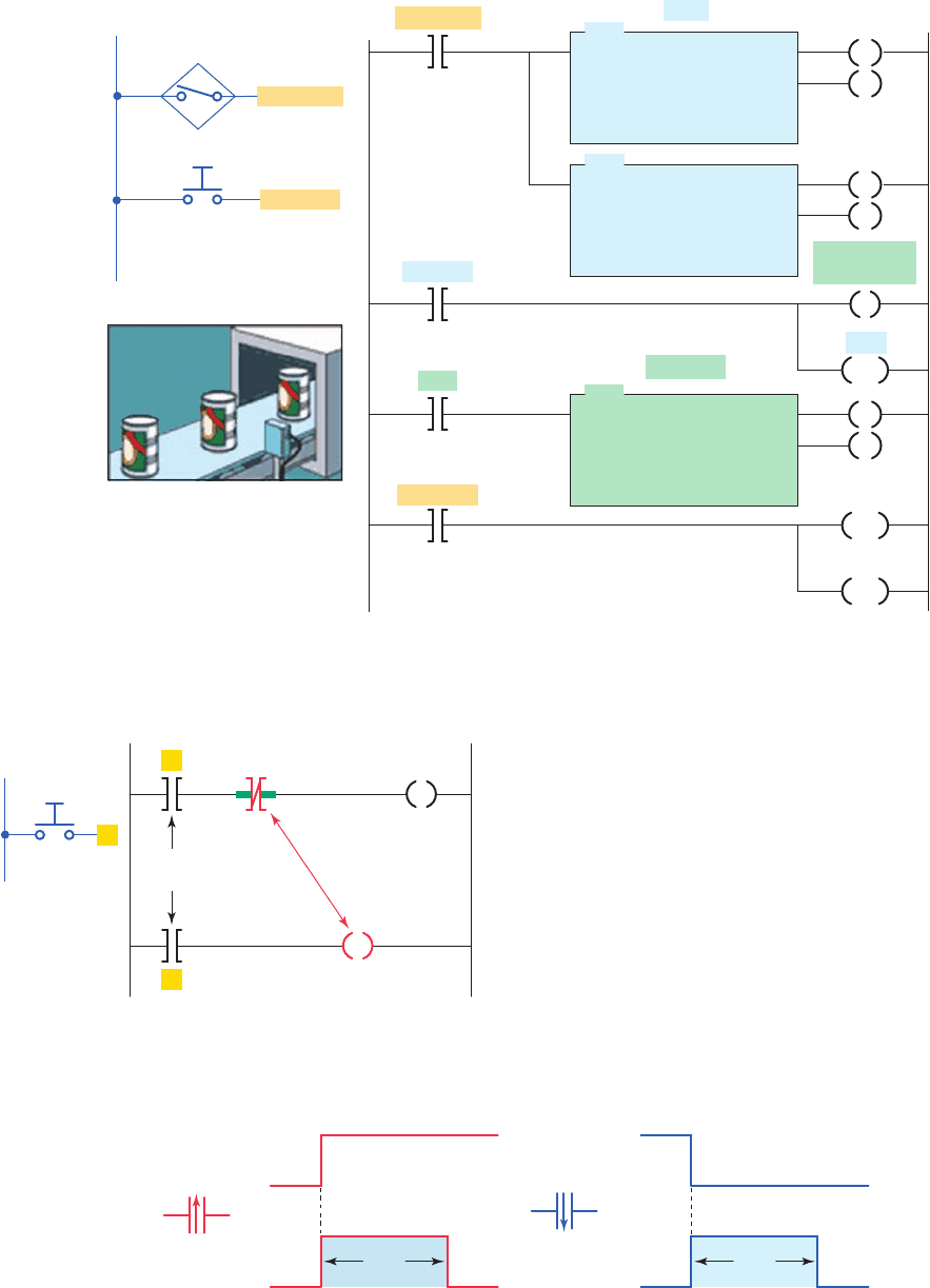
Some PLCs provide transitional contacts or one-shot
instructions in addition to the standard NO and NC contact
instructions. The off-to-on transitional contact instruc-
tion, shown in Figure8-16a , is programmed to provide a
one-shot pulse when the referenced trigger signal makes
a positive (off-to-on) transition. This contact will close
for exactly one program scan whenever the trigger signal
goes from off to on. The contact will allow logic continu-
ity for one scan and then open, even though the trigger-
ing signal may stay on. The on-to-off transitional contact,
shown in Figure8-16b , provides the same operation as
the off-to-on transitional contact instruction, except that
it allows logic continuity for a single scan whenever the
trigger signal goes from an on to an off state.
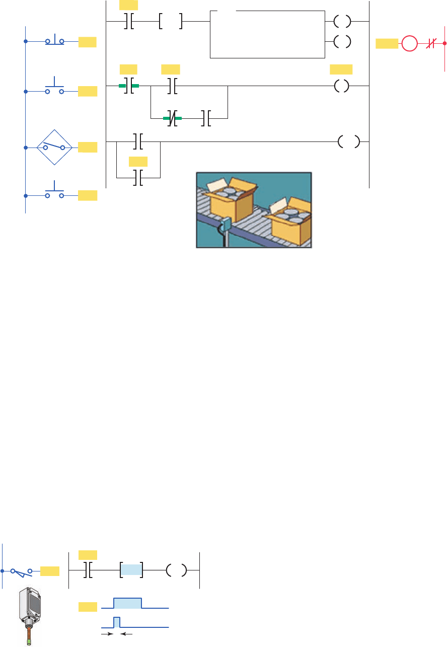
The conveyor motor PLC program of Figure 8-17 il-
lustrates the application of an up-counter along with a
programmed one-shot (OSR) transitional contact instruc-
tion. The counter counts the number of cases coming off
the conveyor. When the total number of cases reaches 50,
the conveyor motor stops automatically. The trucks being
loaded will take a total of only 50 cases of this particular
Figure 8-13 PLC counter program used to stop a motor from running after 10 operations.
CU
CTU
COUNT-UP COUNTER
Counter C5:0
Preset 10
Accumulated 0
DN
RES
C5:0
Reset
Motor
Motor
Motor
Output
Stop Start
Motor
C5:0/DN
Ladder logic program
Stop
Start
Inputs
L1
Start
Reset
Reset
Stop
Start
Reset
OL
L2
M
pet10882_ch08_149-175.indd 155pet10882_ch08_149-175.indd 155 7/23/10 10:01 PM7/23/10 10:01 PM
156 Chapter 8 Programming Counters
product; however, the count can be changed for different
product lines. The operation of the program can be sum-
marized as follows:
• The momentary start button is pressed to start the
conveyor motor M1.
• The passage of cases is sensed by the proximity
switch.
• Cases move past the proximity switch and incre-
ment the counter’s accumulated value with each
false-to-true transition of the switch.
• After a count of 50, the done bit of the counter changes
state to stop the conveyor motor automatically and
reset the counter’s accumulated value to zero.
Figure 8-15 One-shot, or transitional, contact program.
A
A
A
Trigger
input
Internal
relay contact
One-shot
output
Internal
relay coil
L1
Input
Figure 8-16 Transitional contact instructions.
On
Off
On
Off
One
scan
(a) Off-to-on transitional contact
Symbol
On
Off
On
Off
One
scan
(b) On-to-off-transitional contact
Symbol
Figure 8-14 Can-counting program.
CTU
COUNT-UP COUNTER
Counter
Preset
Accumulated
C5:1
10
0
CTU
COUNT-UP COUNTER
Counter
Preset
Accumulated
C5:2
32767
0
CTU
COUNT-UP COUNTER
Counter
Preset
Accumulated
C5:3
300
0
Parts
Packages
PROX-SW
InputsL1
Reset PB
Close box
B3/1
C5:1
C5:1/DN
B3/1
C5:3
C5:2
PROX-SW
Reset PB
Ladder logic program
CU
CU
DN
CU
DN
DN
RES
RES
RES
pet10882_ch08_149-175.indd 156pet10882_ch08_149-175.indd 156 7/23/10 10:01 PM7/23/10 10:01 PM
Programming Counters Chapter 8 157
• The conveyor motor can be stopped and started
manually at any time without loss of the accumu-
lated count.
• The accumulated count of the counter can be reset
manually at any time by means of the count reset
button.
The Allen-Bradley SLC 500 one-shot rising (OSR)
instruction is an input instruction that triggers an event
to occur one time. The OSR instruction is placed in the
ladder logic before the output instruction. When the rung
conditions preceding the OSR instructions go from false-
to-true, the OSR instruction goes true also but for only
one scan. Figure8-18 illustrates the operation of an OSR
rung which can be summarized as follows:
• The OSR, one-shot rising instruction is used to
make the counter reset instruction (RES) true for
one scan when limit switch input LS1 goes from
false to true.
• The OSR is assigned a Boolean bit (B3:0/0) that is
not used anywhere else in the program.
• The OSR instruction must immediately precede the
output instruction.
• When the limit switch closes the LS1 and OSR, input
instructions go from false to true. The OSR instruc-
tion conditions the rung so that the counter C5:1 reset
output instruction goes true for one program scan.
• The output reset instruction goes false and remains
false for successive scans until the input makes an-
other false-to-true transition.
• The OSR bit is set to 1 as long as the limit switch
remains closed.
• The OSR bit is reset to 0 when the limit switch is
opened.
Applications for the OSR instruction include freez-
ing rapidly displayed LED values. Figure8-19 shows a
one-shot instruction used to send data to an output LED
display. The one-shot allows the rapidly changing ac-
cumulated time from the timer to be frozen to ensure a
readable, stable display. The operation of the program is
summarized as follows:
• The accumulated value of timer T4:1 is converted to
Binary Coded Decimal (BCD) and moved to output
word O:6 where an LED display is connected.
Figure 8-17 Case-counting program.
O:2/0O:2/0
Inputs
Output
L1
L2
Stop
Start
Proximity
switch
OL
I:1/1
M1
Reset
Ladder logic program
I:1/1
I:1/2
O:2/0C5:0/DN
I:1/3
I:1/4
RES
C5:0C5:0/DN
CTU
COUNT-UP COUNTER
Counter
Preset
Accumulated
C5:0
50
0
CU
DN
O:2/0
I:1/2
I:1/3
I:1/4
B3:0/0
OSR
Figure 8-18 One-shot rising (OSR) instruction.
C5:1
B3:0/0
One PLC scan
RES
OSR rungInput
B3:0/0
OSR
L1
LS1
LS1
LS1
pet10882_ch08_149-175.indd 157pet10882_ch08_149-175.indd 157 7/23/10 10:01 PM7/23/10 10:01 PM
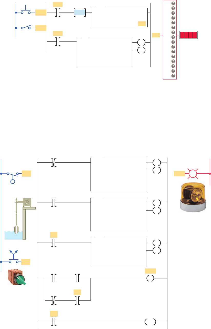
158 Chapter 8 Programming Counters
• When the timer is running, SW (I:1/1) closed, the
accumulated value changes rapidly.
• Closing the momentary pushbutton PB (I:1/0) will
freeze and display the value at that point in time.
The alarm monitor PLC program of Figure8-20 illus-
trates the application of an up-counter used in conjunction
with the programmed timed oscillator circuit studied in
Chapter 7. The operation of the program can be summa-
rized as follows:
• The alarm is triggered by the closing of oat switch FS.
• The light will ash whenever the alarm condition
is triggered and has not been acknowledged,
Figure 8-20 Alarm monitor program.
TON
TIMER ON DELAY
Timer
Time base
Preset
Accumulated
T4:5
1.0
1
0
CTU
COUNT-UP COUNTER
Counter
Preset
Accumulated
C5:1
1
0
Ladder logic program Output
L2
T4:6
C5:1
DN
T4:5
DN
C5:1
DN
FS
FS
SS
C5:1
RES
Light
Light
TON
TIMER ON DELAY
Timer
Time base
Preset
Accumulated
T4:6
1.0
1
0
OFF ON
L1
Inputs
FS
SS
DN
T4:5
DN
EN
EN
CU
DN
DN
DN
Figure 8-19 OSR instruction used to freeze rapidly displayed LED values.
B3:0/0
OSR
TOD
To BCD
Source
Destination
T4:1.ACC
O:6
O:6
I:1/1
PB
SW
I:1/0
TON
TIMER ON DELAY
Timer
Time base
Preset
Accumulated
T4:1
1.0
1000
0
EN
DN
I:1/0
I:1/1
0
1
2
3
4
5
6
7
8
9
10
11
12
13
14
15
0000
OutputInputs
L1
pet10882_ch08_149-175.indd 158pet10882_ch08_149-175.indd 158 7/23/10 10:01 PM7/23/10 10:01 PM
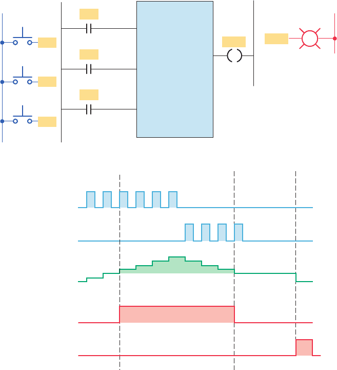
Programming Counters Chapter 8 159
even if the alarm condition clears in the
meantime.
• The alarm is acknowledged by closing selector
switch SS.
• The light will operate in the steady on mode when
the alarm trigger condition still exists but has been
acknowledged.
8.3 Down-Counter
The down-counter instruction will count down or decre-
ment by 1 each time the counted event occurs. Each time
the down-count event occurs, the accumulated value is
decremented. Normally the down-counter is used in con-
junction with the up-counter to form an up/down-counter.
Figure8-21 shows the program and timing diagram for
a generic, block-formatted up/down-counter. The opera-
tion of the program can be summarized as follows:
• Separate count-up and count-down inputs are
provided.
• Assuming the preset value of the counter is 3 and
the accumulated count is 0, pulsing the count-up
input (PB1) three times will switch the output light
from off to on.
• This particular PLC counter keeps track of the num-
ber of counts received above the preset value. As a
result, three additional pulses of the count-up input
(PB1) produce an accumulated value of 6 but no
change in the output.
• If the count-down input (PB2) is now pulsed
fourtimes, the accumulated count is reduced to
2 (624). As a result, the accumulated count
drops below the preset count and the output light
switchesfrom on to off.
• Pulsing the reset input (PB3) at any time will reset the
accumulated count to 0 and turn the output light off.
Figure 8-21 Generic up/down-counter program. (a) Program. (b) Counting
diagram.
Count
up
Count
down
UDC
PR: 003
AC: 000
Ladder logic program Inputs
L1
Light
Light
Output
L2
Reset
PB3
PB3
PB2
PB2
PB1
PB1
(a)
(b)
Count up
Count down
Counter
accumulated
value
Output
Reset
On
Off
On
Off
On
Off
On
Off
123456
1234
0
1
2
3
4
5
65
4
3
2
0Preset value
pet10882_ch08_149-175.indd 159pet10882_ch08_149-175.indd 159 7/23/10 10:01 PM7/23/10 10:01 PM
160 Chapter 8 Programming Counters
Not all counter instructions count in the same man-
ner. Some up-counters count only to their preset values,
and additional counts are ignored. Other up-counters
keep track of the number of counts received above the
counter’s preset value. Conversely, some down-counters
will simply count down to zero and no further. Other
down-counters may count below zero and begin count-
ing down from the largest preset value that can be set
for the PLC’s counter instruction. For example, a PLC
up/down-counter that has a maximum counter preset
limit of 999 may count up as follows: 997, 998, 999,
000, 001, 002, and so on. The same counter would count
down in the following manner: 002, 001, 000, 999, 998,
997, and so on.
One application for an up/down-counter is to keep
count of the cars that enter and leave a parking garage.
Figure8-22 shows a typical PLC program that could be
used to implement this. The operation of the program can
be summarized as follows:
• As a car enters, the enter switch triggers the up-
counter output instruction and increments the accu-
mulated count by 1.
• As a car leaves, the exit switch triggers the down-
counter output instruction and decrements the accu-
mulated count by 1.
• Because both the up- and down-counters have the
same address, C5:1, the accumulated value will be
the same in both instructions as well as the preset.
• Whenever the accumulated value of 150 equals the
preset value of 150, the counter output is energized
by the done bit to light up the Lot Full sign.
• A reset button has been provided to reset the accu-
mulated count.
Figure 8-23 shows an example of the count-down
counter instruction used as part of the Allen-Bradley SLC
500 controller instruction set. The information to be en-
tered into the instruction is the same as for the count-up
counter instruction.
The CTD instruction decrements its accumulated value
by 1 every time it is transitioned. It sets its done bit when
the accumulated value is equal to or greater than the preset
value. The CTD instruction requires the RES instruction
to reset its accumulated value and status bits. Because it
resets its accumulated value to 0, the CTD instruction then
Figure 8-22 Parking garage counter.
Lot full
light
Lot full
light
Ladder logic program
C5:1/DN
Enter
switch
Enter
switch
Exit
switch
Exit
switch
Reset
Reset
Inputs
L1
C5:1
Output
L2
CTU
COUNT-UP COUNTER
Counter C5:1
Preset 150
Accumulated 0
CTD
COUNT-DOWN COUNTER
Counter C5:1
Preset 150
Accumulated 0
CU
CD
DN
DN
RES
Figure 8-23 Count-down counter instruction.
CTD
COUNT-DOWN COUNTER
Counter
Preset
Accumulated
C5:0
10
0
C5:0/CD
Counter enable bit
C5:0/DN
Counter done bit
C5:0/UN
Underflow status bit
C5:0
The reset instruction resets
the counter's accumulated
value back to zero.
CD
DN
RES
pet10882_ch08_149-175.indd 160pet10882_ch08_149-175.indd 160 7/23/10 10:01 PM7/23/10 10:01 PM
Programming Counters Chapter 8 161
counts negative when it transitions. If the CTD instruction
were used by itself with a positive preset value, its done
bit would be reset when the accumulated value reached 0.
Then, counting in a negative direction, the accumulated
value would never reach its preset value and set the done
bit. However, the preset can be entered with a negative
value; then the done bit is cleared when the accumulated
value becomes less than the preset value.
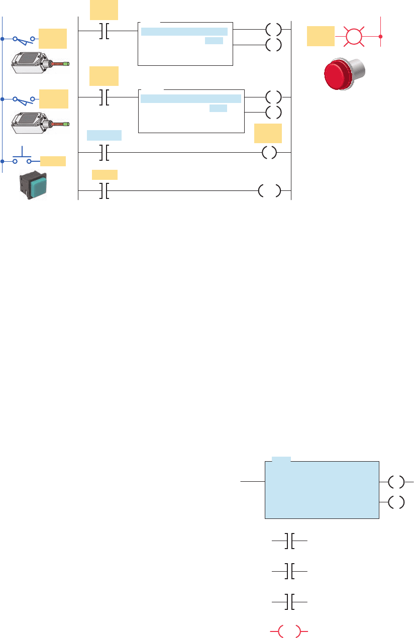
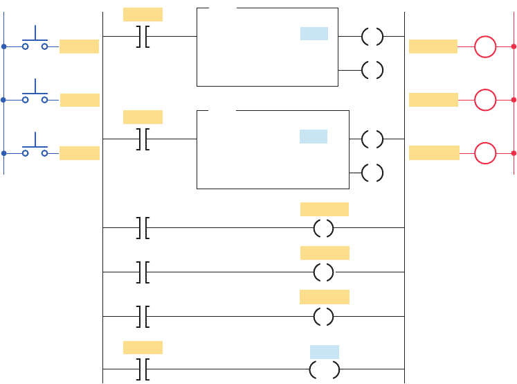
Figure 8-24 shows an up/down-counter program that
will increase the counter’s accumulated value when push-
button PB1 is pressed and will decrease the counter’s ac-
cumulated value when pushbutton PB2 is pressed. Note
that the same address is given to the up-counter instruc-
tion, the down-counter instruction, and the reset instruc-
tion. All three instructions will be looking at the same
address in the counter le. When input A goes from false
to true, one count is added to the accumulated value.
When input B goes from false to true, one count is sub-
tracted from the accumulated value. The operation of the
program can be summarized as follows:
• When the CTU instruction is true, C5:2/CU will be
true, causing output A to be true.
• When the CTD instruction is true, C5:2/CD will be
true, causing output B to be true.
• When the accumulated value is greater than or equal
to the preset value, C5:2/DN will be true, causing
output C to be true.
• Input C going true will cause both counter instruc-
tions to reset. When reset by the RES instruction,
the accumulated value will be reset to 0 and the
done bit will be reset.
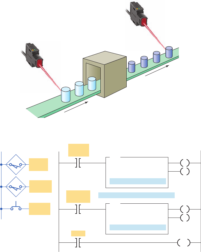
Figure8-25 illustrates the operation of the up/down-
counter program used to provide continuous monitor-
ing of items in process. An in-feed photoelectric sensor
counts raw parts going into the system, and an out-feed
photoelectric sensor counts nished parts leaving the
machine. The number of parts between the in-feed
and out-feed is indicated by the accumulated count of
the counter. Counts applied to the up-input are added,
and counts applied to the down-input are subtracted.
The operation of the program can be summarized as
follows:
• Before start-up, the system is completely empty of
parts, and the counter is reset manually to 0.
• When the operation begins, raw parts move through
the in-feed sensor, with each part generating an up
count.
Figure 8-24 Up/down-counter program.
Input A
Input B
Input C
L1
L2
Ladder logic programInputs
PB1
PB2
Reset
Outputs
Input A
Input B
Input C
CU
DN
CD
C5:2
C5:2
C5:2
CTU
COUNT-UP COUNTER
Counter C5:2
Preset 10
Accumulated 0
CTD
COUNT-DOWN COUNTER
Counter C5:2
Preset 10
Accumulated 0
C5:2
Output B
Output C
Output A
RES
Output A
Output B
Output C
CU
CU
C
B
A
DN
DN
pet10882_ch08_149-175.indd 161pet10882_ch08_149-175.indd 161 7/23/10 10:01 PM7/23/10 10:01 PM
162 Chapter 8 Programming Counters
one scan time. If the input changes faster than one scan
period, the count value will become unreliable because
counts will be missed. When this situation occurs, you
need to use a high-speed counter input or a separate coun-
ter I/O module designed for high-speed applications.
8.4 Cascading Counters
Depending on the application, it may be necessary to
count events that exceed the maximum number allowable
per counter instruction. One way of accomplishing this
count is by interconnecting, or cascading, two counters.
The program of Figure8-26 illustrates the application of
• After processing, nished parts appearing at the out-
feed sensor generate down counts, so the accumu-
lated count of the counter continuously indicates the
number of in-process parts.
• The counter preset value is irrelevant in this ap-
plication. It does not matter whether the counter
outputs are on or off. The output on-off logic is not
used. We have arbitrarily set the counter’s preset
values to50.
The maximum speed of transitions that you can count
is determined by your program’s scan time. For a reli-
able count, your counter input signal must be xed for
Figure 8-25 In-process monitoring program. (a) Process. (b) Program.
(a)
In-feed
(raw parts)
Out-feed
(finished parts)
Photoelectric
sensor
Photoelectric
sensor
Material
processing system
(b)
Ladder logic program
RESETReset
IN-Feed
count
IN-Feed
count
OUT-Feed
count
OUT-Feed
count
Inputs
L1
Reset to
zero
CTU
COUNT-UP COUNTER
Counter
Preset
Accumulated
Accumulated = No. in-process parts
C5:1
50
0
CTD
COUNT-DOWN COUNTER
Counter
Preset
Accumulated
C5:1
50
0
C5:1
CU
CD
DN
DN
RES
pet10882_ch08_149-175.indd 162pet10882_ch08_149-175.indd 162 7/23/10 10:01 PM7/23/10 10:01 PM