Petruzella F.D. Programmable Logic Controllers
Подождите немного. Документ загружается.

Program Control Instructions Chapter 9 183
(a)
Solenoid
Weight
sensor
Pilot light
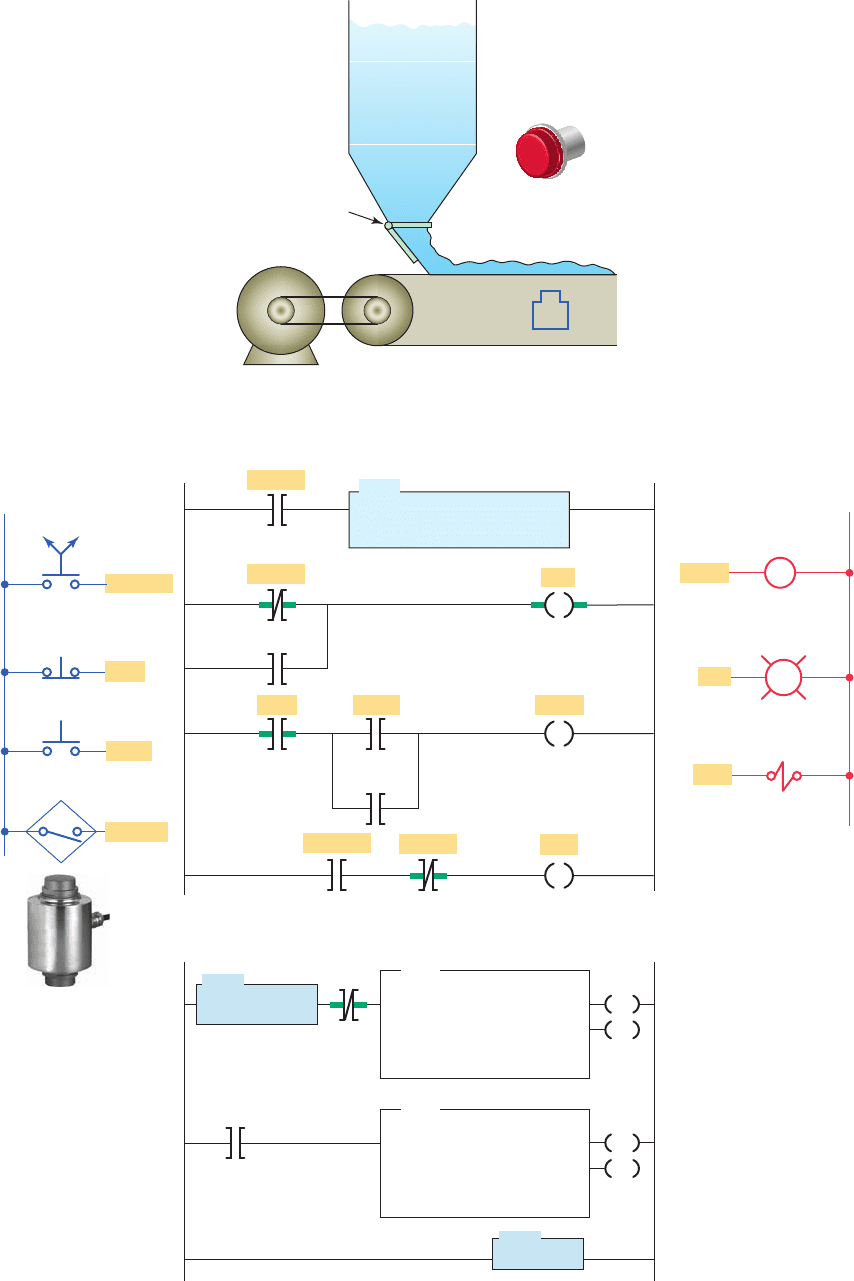
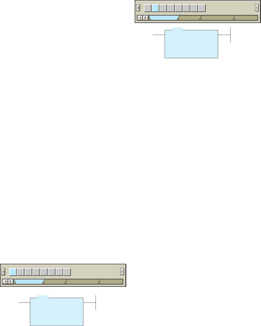
Figure 9-11 Flashing pilot light subroutine. (a) Process. (b) Program.
OFF/ON
Sensor
Sensor
Sensor
SBR
SUBROUTINE
Main program
file 2
Subroutine
file 3
(b)
L1
L2
Inputs
Stop
Stop
M1
Outputs
PL1
PL1
OFF/ON
SOL
SOL
Motor
Motor
Motor
T4:1/EN
T4:0/DN
T4:1/DN
JSR
JUMP-TO-SUBROUTINE
SBR file number
T4:0
1.0
1
0
TON
TIMER ON DELAY
Timer
Time base
Preset
Accumulated
DN
EN
T4:1
1.0
1
0
TON
TIMER ON DELAY
Timer
Time base
Preset
Accumulated
DN
EN
RET
RETURN
U:3
Sensor
PL1
Start
Start
pet10882_ch09_176-199.indd 183pet10882_ch09_176-199.indd 183 7/23/10 10:05 PM7/23/10 10:05 PM
184 Chapter 9 Program Control Instructions
conveyor system with a ashing pilot light as a subrou-
tine. The operation of the program can be summarized as
follows:
• If the weight on the conveyor exceeds a preset
value, the solenoid is de-energized and pilot light
PL1will begin ashing.
• When the weight sensor switch closes, the JSR is
activated and directs the processor scan to jump to
the subroutine U:3.
• The subroutine program is scanned and pilot light
PL1 begins ashing.
• When the weight sensor switch opens, the proces-
sor will no longer scan the subroutine area and pilot
light PL1 will return to its normal on state.
The Allen-Bradley SLC 500 controller main program
is located in program le 2 whereas subroutines are as-
signed to program le numbers 3 to 255. Each subroutine
must be programmed in its own program le by assigning
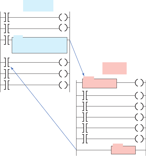
it a unique le number. Figure9-12 illustrates the proce-
dure for setting up a subroutine and can be summarized
as follows:
• Note each ladder location where a subroutine should
be called.
• Create a subroutine le for each location. Each sub-
routine le should begin with an SBR instruction.
• At each ladder location where a subroutine is called,
program a JSR instruction specifying the subroutine
le number.
• The RET instruction is optional.
– The end of a subroutine program will cause a re-
turn to the main program.
– If you want to end a subroutine program before it
executes to the end of program le, a conditional
return (RET) instruction may be used.
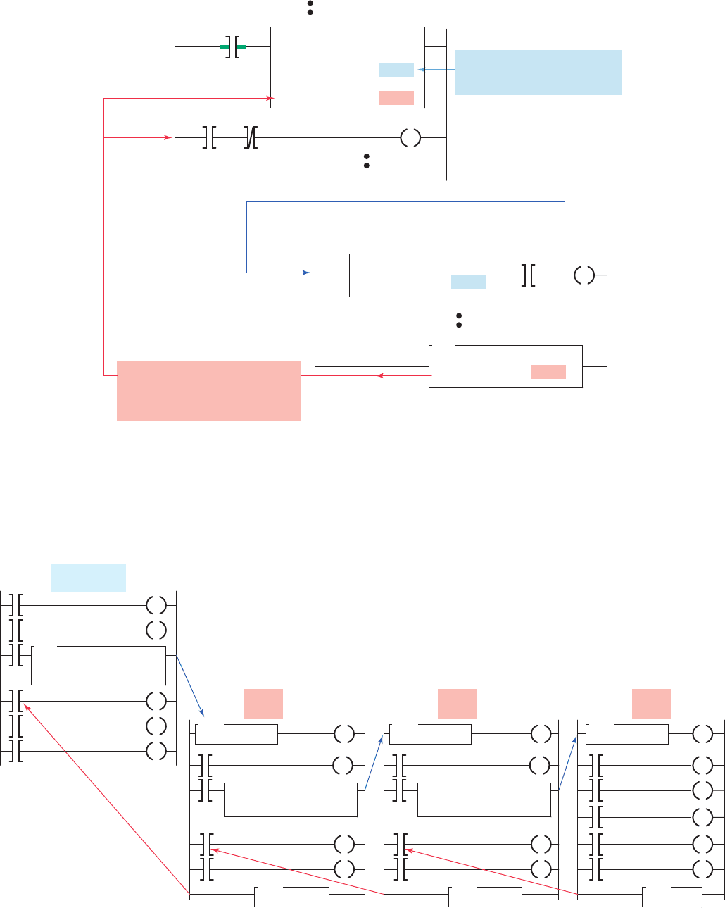
An optional SBR instruction is the header instruction
that stores incoming parameters. This feature lets you
pass selected values to a subroutine before execution
so the subroutine can perform mathematical or logi-
cal operations on the data and return the results to the
main program. For example, the program shown in Fig-
ure9-13 will cause the scan to jump from the main pro-
gram le to program le 4 when input A is true. When
the scan jumps to program le 4, data will also be passed
from N7:30 to N7:40. When the scan returns to the main
program from program le 4, data will be passed from
N7:50 to N7:60.
Nesting subroutines allows you to direct program ow
from the main program to a subroutine and then to another
subroutine, as illustrated in Figure9-14 . Nested subrou-
tines make complex programming easier and program op-
eration faster because the programmer does not have to
continually return from one subroutine to enter another.
Programming nested subroutines may cause scan time
problems because while the subroutine is being scanned,
the main program is not. Excessive delays in scanning the
main program may cause the outputs to operate later than
required. This situation may be avoided by updating criti-
cal I/O using immediate input and/or immediate output
instructions.
9.4 Immediate Input and Immediate
Output Instructions
The immediate input and immediate output instructions
interrupt the normal program scan to update the input
image table le with current input data or to update an
output module group with the current output image table
le data. These instructions are intended to be used only
for time-critical I/O data.
The immediate input (IIN) Allen-Bradley PLC-5 in-
struction is used to read an input condition before the I/O
update is performed. This operation interrupts the pro-
gram scan when it is executed. After the immediate input
instruction is executed, normal program scan resumes.
This instruction is used with critical input devices that re-
quire updating in advance of the I/O scan.
Figure 9-12 Setting up a subroutine fi le.
JSR
JUMP-TO-SUBROUTINE
SBR file number 3
Main program
file 2
SBR
SUBROUTINE
RET
RETURN
Subroutine
file 3
pet10882_ch09_176-199.indd 184pet10882_ch09_176-199.indd 184 7/23/10 10:05 PM7/23/10 10:05 PM
Program Control Instructions Chapter 9 185
Figure 9-13 Passing subroutine parameters.
RETURN ( )
Return parameter N7:50
RET
JSR
Input A
Execution resumes
JUMP-TO-SUBROUTINE
Program file 4
Input parameter N7:30
Return parameter N7:60
SUBROUTINE
Input parameter N7:40
Subroutine
file 4
Main ladder program
Return parameter returned to the
address that you specified in the
JSR instruction when execution
returns to the main ladder program.
SBR
Input parameter passed to the
SBR instruction when execution
jumps to the subroutine file.
Figure 9-14 Nested subroutines.
JSR
JUMP-TO-SUBROUTINE
SBR file 3
JSR
JUMP-TO-SUBROUTINE
SBR file 4
Main program
file 2
SBR
SUBROUTINE
RET
RETURN
Level 1
file 3
JSR
JUMP-TO-SUBROUTINE
SBR file 5
SBR
SUBROUTINE
RET
RETURN
Level 2
file 4
SBR
SUBROUTINE
RET
RETURN
Level 3
file 5
pet10882_ch09_176-199.indd 185pet10882_ch09_176-199.indd 185 7/23/10 10:05 PM7/23/10 10:05 PM
186 Chapter 9 Program Control Instructions
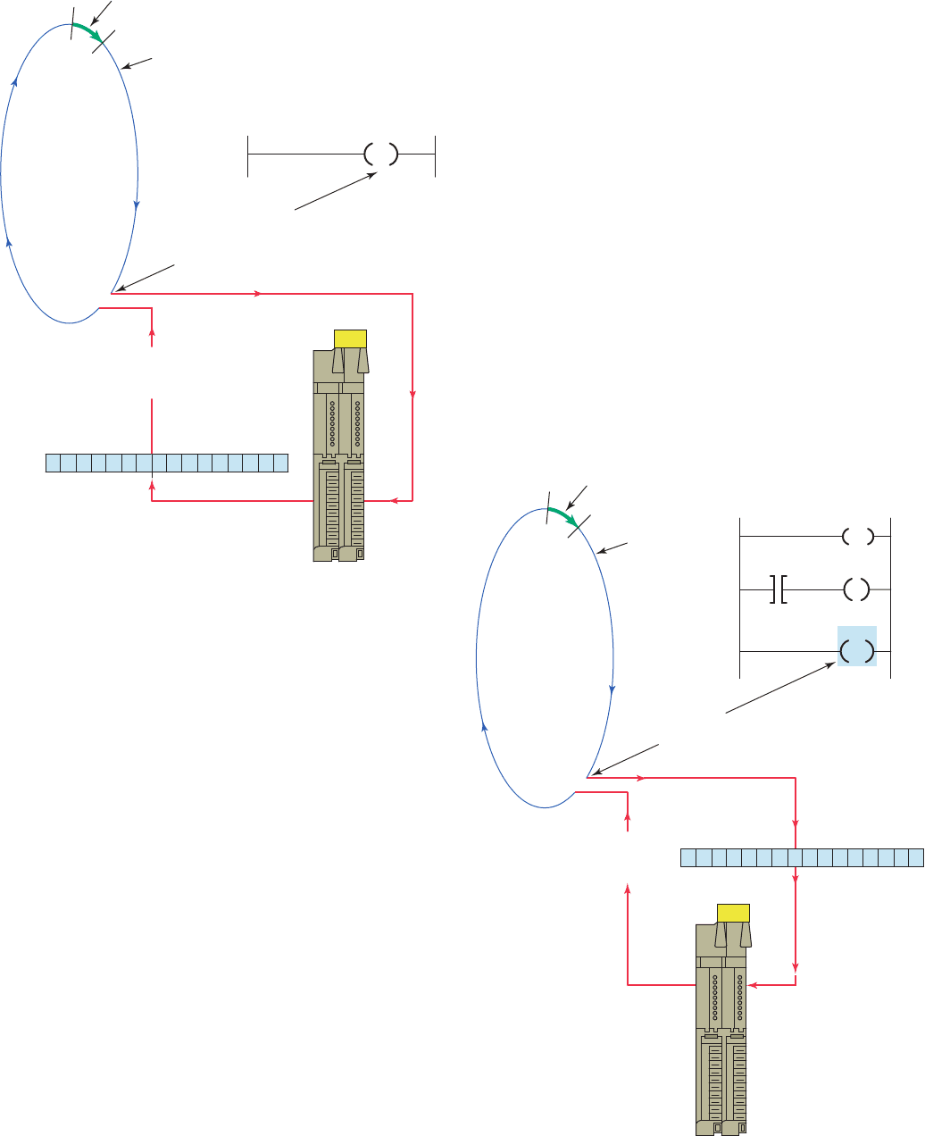
The operation of the immediate input instruction is il-
lustrated in Figure9-15 . When the program scan reaches
the immediate input instruction, the scan is interrupted
and the bits of the addressed word are updated. The
immediate input is most useful if the instruction asso-
ciated with the critical input device is at the middle or
toward the end of the program. The immediate input is
not needed near the beginning of the program since the
I/O scan has just occurred at that time. Although the im-
mediate input instruction speeds the updating of bits, its
scan-time interruption increases the total scan time of the
program. The operation of the program can be summa-
rized as follows:
• When the scan reaches a true IIN instruction, the
scan is interrupted.
• The processor updates 16 bits in the input
image table at the location indicated on the IIN
instruction.
• The two-digit address on the IIN instruction is com-
posed of the rack number ( rst digit) and the I/O
group number (second digit) containing the input or
inputs and needs immediate updating.
The immediate output (IOT) Allen-Bradley PLC-5 in-
struction is a special version of the output energize in-
struction used to update the status of an output device
before the I/O update is performed. The immediate output
is used with critical output devices that require updating in
advance of the I/O scan. When the program scan reaches
the immediate output instruction, the scan is interrupted
and the bits of the addressed word are updated. The opera-
tion of the immediate output instruction is illustrated in
Figure9-16 and can be summarized as follows:
• When the program scan reaches a true IOT instruc-
tion, the scan is interrupted and the data in the
output image table at the word address on the in-
struction are transferred to the real-world outputs.
• In this example, the IOT instruction follows the out-
put energize instruction.
• Thus, the output image table word is updated rst,
and then the data are transferred to the real-world
outputs.
Figure 9-15 Immediate input instruction.
Ι/O scan
Program scan
Immediate input instruction
interrupts program scan
and examines bits in word
I:012 here in program
Returns to
program
scan
Word I:012
2
Module
group
(input)
Rack 1
12
IIN
Immediate output instruction
interrupts program scan
Word O:013
Returns to
program
scan
Module
group
(output)
Rack 1
12
IIN
13
IOT
O:013
I:012
07
11
I/O scan
Program scan
3
Figure 9-16 Immediate output instruction.
pet10882_ch09_176-199.indd 186pet10882_ch09_176-199.indd 186 7/23/10 10:05 PM7/23/10 10:05 PM
Program Control Instructions Chapter 9 187
• This allows the programmer to update only sections
of the inputs to be used throughout the rest of the
program.
The immediate output with mask (IOM) instruction is
shown in Figure 9-18 . The IOM operates on the physi-
cal outputs assigned to a particular word of a slot. When
the IOM rung is true, the program scan is interrupted to
update output data to the module located in the slot speci-
ed in the instruction. These data are then available to the
commands in the ladder following the IOM instruction.
The parameters entered are basically the same as those
entered for the IIM instruction.
Processor communication with the local chassis is
many times faster than communication with the remote
chassis. This is due to the fact that local I/O scan is
synchronous with the program scan and communication
is in parallel with the processor, whereas the remote
I/O scan is asynchronous with the program scan and
communication with remote I/O is serial. For this rea-
son, fast-acting devices should be wired into the local
chassis.
9.5 Forcing External I/O Addresses
The force function is essentially a manual override con-
trol function. Forcing allows the PLC user to turn an ex-
ternal input or output on or off from the keyboard of the
programming device. This is accomplished regardless of
the actual state of the eld device. The forcing capability
allows a machine or process to continue operation until a
faulty eld device can be repaired. It is also valuable dur-
ing start-up and troubleshooting of a machine or process
to simulate the action of portions of the program that have
not yet been implemented.
Forcing inputs manipulates the input image table le
bits and thus affects all areas of the program that use those
bits. The forcing of inputs is done just after the input scan.
When we force an input address, we are forcing the sta-
tus bit of the instruction at the I/O address to an on or
The Allen-Bradley SLC 500 PLC’s immediate I/O
instructions contain a few improvements over those of
the PLC-5. The SLC 500’s instructions, which are called
immediate input with mask (IIM) and immediate out-
put with mask (IOM), allow the programmer to specify
which of the 16 bits are to be copied from an input mod-
ule to the input image data table (or from the output
image table to an output module). The other bits in the
input image table or output module are not affected by
these instructions. In addition, the SLC 500 instructions
allow you to input or output a series of data words from
a single input module or output a series of data words to
an output module.
The immediate input with mask (IIM) instruction is
shown in Figure9-17 . The IIM instruction operates on
the inputs assigned to a particular word of a slot. When
the IIM rung is true, the program scan is interrupted, and
data from a speci c input slot are transferred through
the mask to the input data le. These data are then avail-
able to the commands in the ladder following the IIM
instruction. The following parameters are entered in the
instruction:
Slot Speci es the slot and word that contain the data
to be updated. For example, I:3.0 means the input of
slot 3, word 0.
Mask Speci es either a hex constant or a register
address. For the mask, a 1 in the bit position passes
data from the source to the destination. A 0 inhibits
or blocks bits from passing from the source to the
destination.
Length Used to transfer more than one word per
slot.
The program operation of the instruction is summarized
as follows:
• The IIM instruction retrieves data from I:1.0 and
passes it through the mask.
• The mask permits only the four least signi cant bits
to be moved to the input register I:1.0.
Figure 9-17 Immediate input with mask (IIM) instruction.
IIM IOM SYC MSG IIE IID
Input/Output
Compare
Compute/Math
RPI REF
Move/Logic
IIM
Immediate Input w/ Mask
Slot
Mask
Length
I:1.0
000Fh
1
Figure 9-18 Immediate output with mask (IOM) instruction.
IIM IOM SYC MSG IIE IID
Input/Output
Compare
Compute/Math
RPI REF
Move/Logic
IOM
Immediate Output w/ Mask
Slot
Mask
Length
O:4.0
0FFFh
2
pet10882_ch09_176-199.indd 187pet10882_ch09_176-199.indd 187 7/23/10 10:05 PM7/23/10 10:05 PM
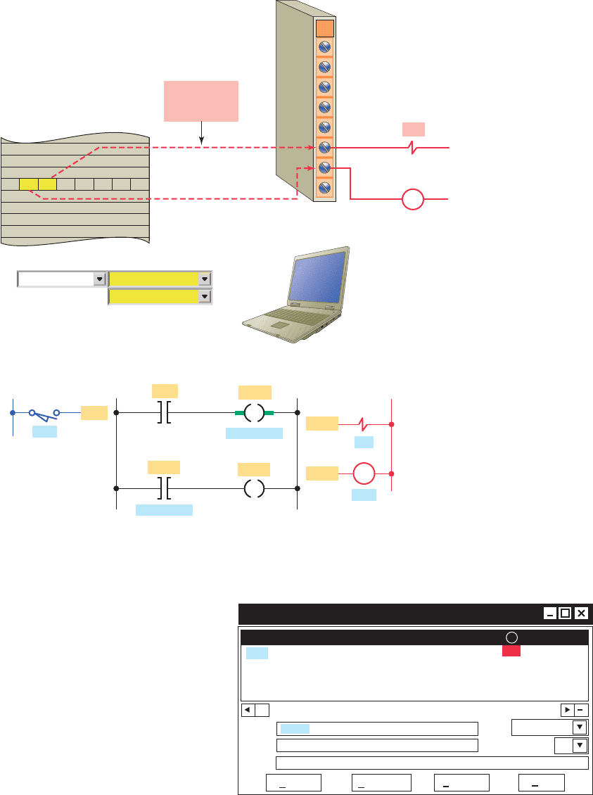
188 Chapter 9 Program Control Instructions
bit of the output instruction at the address is usually not
affected. Figure 9-20 illustrates how an output is forced
on. The operation of the program can be summarized as
follows:
• The processor ignores the actual state of solenoid
output O:2/5.
• The programming device sets the force state in the
output force data le and the PLC implements the
force to turn solenoid output O:2/5 on even though
the output image table le indicates that the user
logic is setting the point to off.
• M output O:2/6 remains off because the status
bit of output O:2/5 is not affected by the force
instruction.
• Not all brands of PLCs operate this way. For ex-
ample, forcing an output with a GE Fanuc controller
will cause the contacts that have the same address as
the output to also change to the appropriate state.
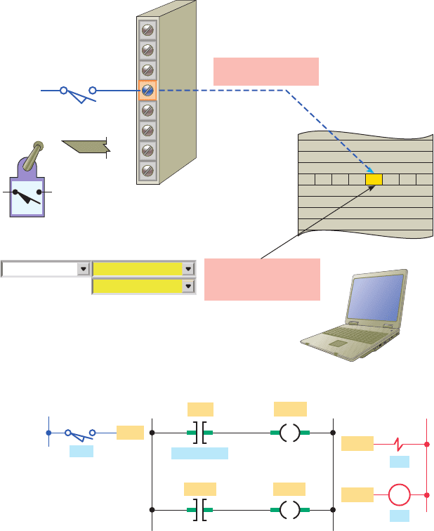
off state. Figure 9-19 illustrates how an input is forced
on. The operation of the program can be summarized as
follows:
• The processor ignores the actual state of input limit
switch I:1/3.
• Although limit switch I:1/3 is off (0 or false) the
processor considers it as being in the on (1 or true)
state.
• The program scan records this, and the program is
executed with this forced status.
• In other words, the program is executed as if the
limit switch were actually closed.
Forcing outputs affects only the addressed output ter-
minal. Therefore, since the output image table le bits are
unaffected, your program will be unaffected. The forcing
of outputs is done just before the output image table le is
updated. When we force an output address, we are forcing
only the output terminal to an on or off state. The status
OFF
Input image table
1
Input module
I:1/3
Field input
device
Programming terminal
forces the state of
input I:1/3 ON (1)
O:2/5
O:2/5 O:2/6
Ladder logic program
I:1/3
M
L2
OutputsInput
OFF
ON
ON
L1
Force> ON
O:2/5
O:2/6
I:1/3
Ladder
logic
program
Forces Exist
Forces Enabled
ONLINE
Actual state of input
device (0) ignored
Figure 9-19 Forcing an input on.
pet10882_ch09_176-199.indd 188pet10882_ch09_176-199.indd 188 7/23/10 10:05 PM7/23/10 10:05 PM
Program Control Instructions Chapter 9 189
le online. With RSLogix 500 software, the steps are as
follows:
1. Open the program le in which you want to force
the logic on or off.
Overriding of physical inputs on conventional relay
control systems can be accomplished by installing
hardwire jumpers. With PLC control hardwire jumpers
are not necessary because the input data table values
can be forced to an on or off state. The force func-
tion allows you to override the actual status of external
input circuits by forcing external data bits on or off.
Similarly, you can override the processor logic and
status of output data file bits by forcing output bits
on or off. By forcing outputs off, you can prevent the
controller from energizing those outputs even though
the ladder logic, which normally controls them, may
be true. In other instances, outputs may be forced on
even though logic for the rungs controlling those out-
puts may be false.
Figure9-21 shows the forces version of the data table
with bit I:1/3 forced on. You can enter and enable or
disable forces while you are monitoring your le off-
line, or in any processor mode while monitoring your
Figure 9-20 Forcing an output on.
O:2/5
O:2/5
O:2/6
Ladder logic program
I:1/3
M
L2
OutputsInput
OFF
ON
OFF
L1
Force> ON
Force> ON
O:2/5
O:2/6
I:1/3
Ladder
logic
program
Forces Exist
Forces Enabled
ONLINE
Output image table
Status of bit
O:2/5 remains
at 0
Field output
devices
O:2/5
O:2/6
OFF
ON
Output module
M
00
Figure 9-21 Forces version of the data table with bit I:1/3
forced on.
Offset 15
.
14
.
13
.
12
.
11
.
10
.
9
.
8
.
7
.
6
.
5
.
4
.
2
.
.
1
.
.
0
.
.
3
1
I:1.0
I:2.0
.
Data File I1 (bin) . . INPUT Forces
Radix:
Columns:
Symbol:
Desc:
Enable
Remove All
Data File
Help
I:1.0/3
pet10882_ch09_176-199.indd 189pet10882_ch09_176-199.indd 189 7/23/10 10:05 PM7/23/10 10:05 PM
190 Chapter 9 Program Control Instructions
example, if maintenance personnel are performing rou-
tine maintenance on a de-energized motor, the machine
may suddenly become energized by someone forcing the
motor to turn on. This is why a hardwired master control
circuit is required for the I/O rack. The hardwired circuit
will provide a method of physically removing power to
the I/O system, thereby ensuring that it is impossible to
energize any inputs or outputs when the master control
is off.
9.6 Safety Circuitry
Suf cient emergency circuits must be provided to stop ei-
ther partially or totally the operation of the controller or
the controlled machine or process. These circuits should
be hardwired outside the controller so that in the event of
total controller failure, independent and rapid shutdown
is available.
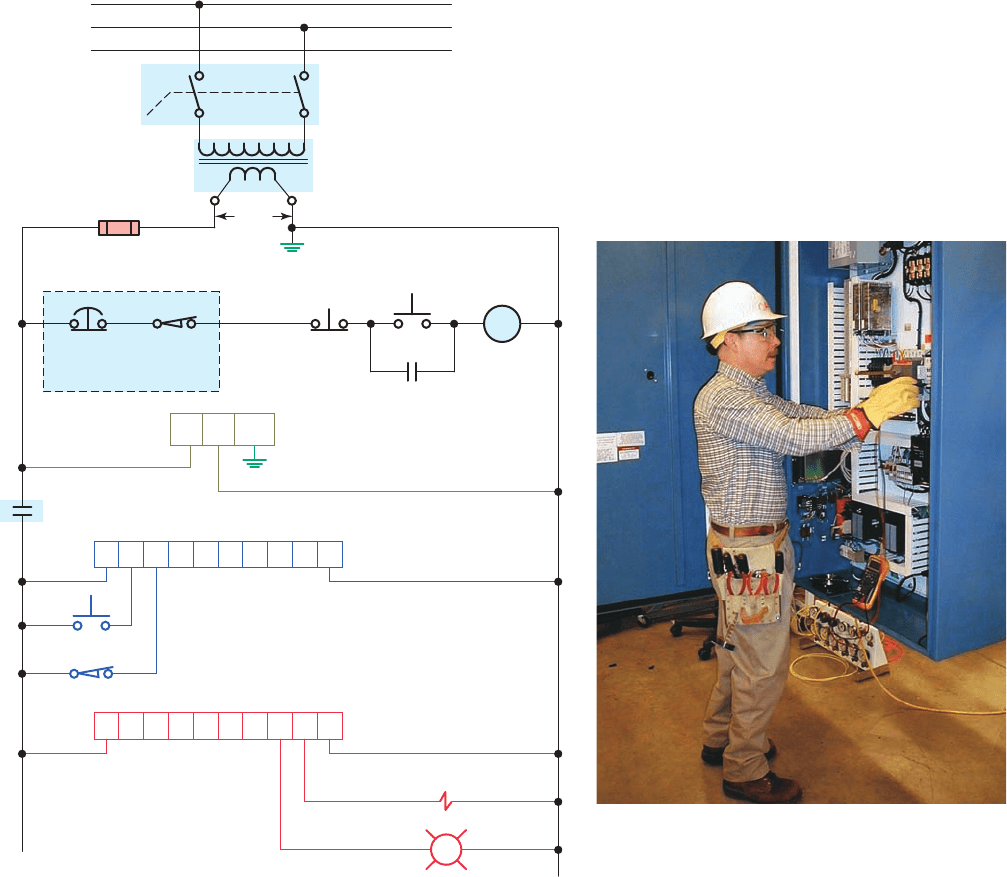
Figure9-23 shows typical safety wiring requirements
for a PLC installation. The safety requirements of this in-
stallation can be summarized as follows:
• A main disconnect switch is installed on the
incoming power lines as a means of removing
power from the entire programmable controller
system.
• The main power disconnect switch should be lo-
cated where operators and maintenance personnel
have quick and easy access to it. Ideally, the discon-
nect switch is mounted on the outside of the PLC
enclosure so that it can be accessed without opening
the enclosure.
• In addition to disconnecting electrical power, you
should de-energize, lock out, and tag all other
sources of power (pneumatic and hydraulic) before
you work on a machine or process controlled by the
controller.
• An isolation transformer is used to isolate the con-
troller from the main power distribution system and
step the voltage down to 120 VAC.
• A hardwired master control relay is included to pro-
vide a convenient means for emergency controller
shutdown. Because the master control relay allows
the placement of several emergency-stop switches
in different locations, its installation is important
from a safety standpoint.
• Overtravel limit switches or mushroom head emer-
gency stop pushbuttons are wired in series so that
when one of them opens, the master control is
de-energized.
• This removes power to input and output device
circuits. Power continues to be supplied to the
2. With the right mouse button, click the I/O bit you
want to force.
3. From the menu that appears, select Go to Data Table
or select Force On or Force Off.
4. From the associated data table that appears, click on
the Forces button.
5. The Forces version of the data table appears with
the selected bit highlighted. Click on this bit with
the right mouse button.
6. From the menu that appears, you can force the se-
lected bit on or off.
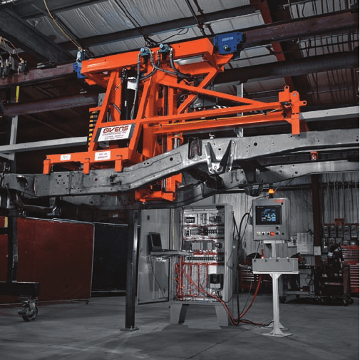
Exercise care when you use forcing functions. If
used incorrectly, force functions can cause injuries
to persons working around a system, and/or equip-
ment damage. For this reason, forcing functions should
be used only by personnel who completely understand
the circuit and the process machinery or driven equip-
ment ( Figure9-22 ). You must understand the potential
effect that forcing given inputs or outputs will have on
machine operation in order to avoid possible personal
injury and equipment damage. Before using a force
function, check whether the force acts on the I/O point
only or whether it acts on the user logic as well as on the
I/O point. Most programming terminals and PLC CPUs
provide some visible means of alerting the user that a
force is in effect.
In situations in which rotating equipment is involved,
the force instruction can be extremely dangerous. For
Figure 9-22 Exercise care when you use forcing functions.
Source: Courtesy Givens Engineering Inc.
pet10882_ch09_176-199.indd 190pet10882_ch09_176-199.indd 190 7/23/10 10:05 PM7/23/10 10:05 PM
Program Control Instructions Chapter 9 191
electromechanical component must not be dependent on
electronic components (hardware or software). Any part
can fail, including the switches in a master control relay
circuit. The failure of one of these switches would most
likely cause an open circuit, which would be a safe power-
off failure. However, if one of these switches shorts out, it
no longer provides any safety protection. These switches
should be tested periodically to ensure that they will stop
machine motion when needed. Never alter these circuits
to defeat their function. Serious injury or machine dam-
age could result.
controller power supply so that any diagnostic
indicators on the processor module can still be
observed.
• Note that the master control relay is not a substitute
for a disconnect switch. When you are replacing
any module, replacing output fuses, or working on
equipment, the main disconnect switch should be
pulled and locked out.
The master control relay must be able to inhibit all
machine motion by removing power to the machine I/O
devices when the relay is de-energized. This hardwired
L
Power
mains
Main disconnect switch
Step-down
isolation transformer
Fuse
120
VAC
Emergency stop switches
Emergency
stop
Overtravel
limit
switch
Stop Start
MCR
Machine
start/stop
buttons
Master
control
relay
PLC Control Panel
PLC power
supply
GND
L3
L2
L1
MCR
L1 2
MCR
L1 L2
PLC output module
PLC input module
L287654321L1
L287654321L1
Figure 9-23 Safety wiring requirements for a PLC installation.
Source: Courtesy Minarik Automation & Control.
pet10882_ch09_176-199.indd 191pet10882_ch09_176-199.indd 191 7/23/10 10:05 PM7/23/10 10:05 PM
192 Chapter 9 Program Control Instructions
• Safety PLCs use power supplies designed speci -
cally for use in safety control systems and redun-
dant backplane circuitry between the controller and
I/O modules.
Safety considerations should be developed as part
of the PLC program. A PLC program for any applica-
tion will be only as safe as the time and thought spent
on both personnel and hardware considerations make
it. One such consideration involves the use of a motor
starter auxiliary seal-in contact, shown in Figure9-25 ,
in place of the programmed contact referenced to the
output coil instruction. The use of the eld-generated
starter auxiliary contact status in the program is more
costly in terms of eld wiring and hardware, but it is
safer because it provides positive feedback to the pro-
cessor about the exact status of the motor. Assume,
for example, that the OL contact of the starter opens
under an overload condition. The motor, of course,
would stop operating because power would be lost to
the starter coil. If the program was written using an
examine-on contact instruction referenced to the out-
put coil instruction as the seal-in for the circuit, the
processor would never know that power had been lost
to the motor. When the OL was reset, the motor would
restart instantly, creating a potentially unsafe operating
condition.
Another safety consideration concerns the wiring
of stop buttons. A stop button is generally considered
a safety function as well as an operating function. As
such, all stop buttons should be wired using a nor-
mally closed contact programmed to examine for an on
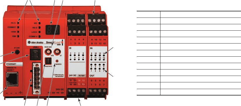
Safety PLCs, such as the one shown in Figure9-24 ,
are now available for applications that require more ad-
vanced safety functionality. A safety PLC is typically
certi ed by third parties to meet rigid safety and reliabil-
ity requirements of international standards. Both stan-
dard and safety PLCs have the ability to perform control
functions but a standard PLC was not initially designed
to be fault tolerant and fail-safe. That is the fundamental
difference.
Some of the differences between standard and safety
PLCs include the following:
• A standard PLC has one microprocessor that
executes the program, Flash memory area that
stores the program, RAM for making calcula-
tions, ports for communications, and I/O for
detection and control of the machine. In contrast,
a safety PLC has redundant microprocessors,
Flash and RAM that are continuously moni-
tored by a watchdog circuit, and a synchronous
detection circuit. Redundancy is duplication. The
probability of hazards arising from one malfunc-
tion in an electrical circuit can be minimized
by creating partial or complete redundancy
(duplication).
• Standard PLC inputs provide no internal means for
testing the functionality of the input circuitry. By
contrast, safety PLCs have an internal output circuit
associated with each input for the purpose of testing
the input circuitry. Inputs are driven both high and
low for very short cycles during runtime to verify
their functionality.
71246
11
5
12
10
37
8
9
Number Feature
1 Module status indicators
2 Alphanumeric display
3 Node address switches
4 Baud rate switches
5 USB port
6 DeviceNet communication connector
7 Terminal connectors
8 Input status indicators
9 Output status indicators
10 IP address desplay switch
11 Ethernet connector
12 Service switch
Figure 9-24 Safety PLC.
Source: Image Used with Permission of Rockwell Automation, Inc.
pet10882_ch09_176-199.indd 192pet10882_ch09_176-199.indd 192 7/23/10 10:06 PM7/23/10 10:06 PM