Petruzella F.D. Programmable Logic Controllers
Подождите немного. Документ загружается.

Data Manipulation Instructions Chapter 10 203
• Where there is a 1 in the mask, data will pass from
the source to the destination.
• Where there is a 0 in the mask, data in the destina-
tion will remain in their last state.
• Status in bits 4–7 are unchanged due to zeroes in the
mask (remained in their last state).
• Status in bits 0–3 and 8–15 were copied from the
source to destination when the MVM instruction went
true.
• The mask must be the same word size as the source
and destination.
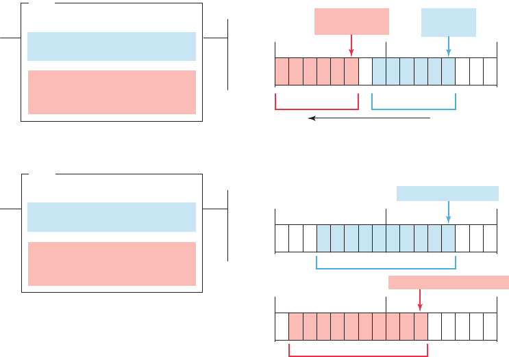
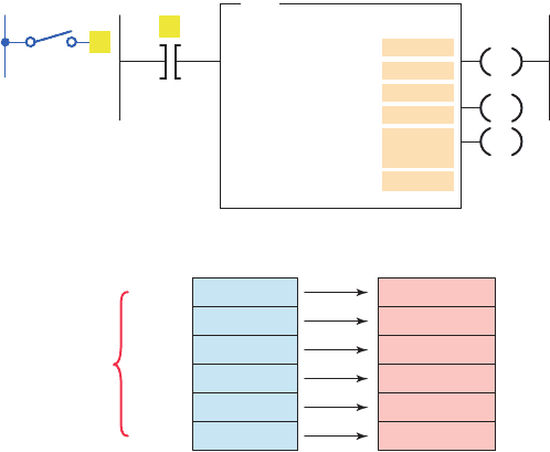
The bit distribute (BTD) instruction is used to move
bits within a word or between words, as illustrated in
Figure 10-6 . On each scan, when the rung that contains
the BTD instruction is true, the processor moves the bit
eld from the source word to the destination word. Bits
are lost if they extend beyond the destination word; the
bits are not wrapped to the next higher word. To move data
within a word, enter the same address for the source and
destination. The source data will remain unchanged but
the instruction writes over the destination with the speci-
ed bits.
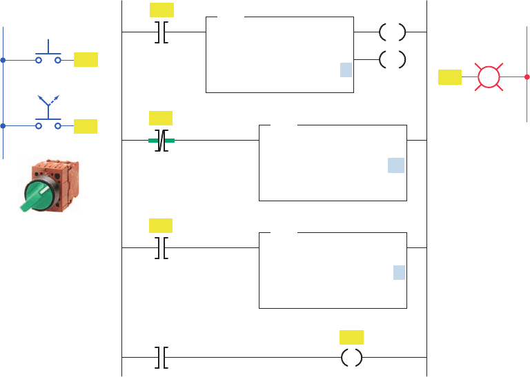
The program of Figure10-7 illustrates how the move
(MOV) instruction can be used to create variable preset
timer values. A two-position selector switch is operated
to select one of two preset timer values. Operation of the
program can be summarized as follows:
• When the selector switch is in the open 10 s posi-
tion, rung 2 has logic continuity and rung 3 does
not.
• As a result, the value 10 stored at the source ad-
dress, N7:1, is copied into the destination address,
T4:1.PRE.
• Therefore, the preset value of timer T4:1 will
change from 0 to 10.
• When pushbutton PB1 is closed, there will be
a 10 s delay period before the pilot light is
energized.
• When the selector switch is in the closed 5 s posi-
tion, rung 3 has logic continuity and rung 2 does
not.
• As a result, the value 5 stored at the source address,
N7:2, is copied into the destination address, T4:1.
PRE.
• Closing pushbutton PB1 will now result in a
5 s time-delay period before the pilot light is
energized.
Figure 10-6 Bit distribute (BTD) instruction.
(a) Moving bits within words.
N70:22
3
N70:22
10
6
BTD
BIT FIELD DISTRIBUTION
Source
Source bit
Destination
Destination bit
Length
1 0 1 1 0 1 1 0 1 1 0 1 N70:22
0008
Destination bit
N70:22/10
Source bit
N70:22/3
07
15
(b) Moving bits between words.
0 111 0 1 1 1 0 1 N7:020
0008 0715
110 110 1 1 0 1 N7:022
0008 0715
N7:020
3
N7:022
5
10
BTD
BIT FIELD DISTRIBUTION
Source
Source bit
Destination
Destination bit
Length
Source bit N7:020/3
Destination bit N7:022/5
pet10882_ch10_200-225.indd 203pet10882_ch10_200-225.indd 203 7/27/10 10:45 PM7/27/10 10:45 PM
204 Chapter 10 Data Manipulation Instructions
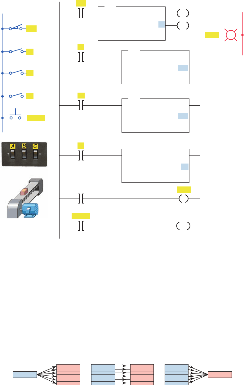
The program of Figure10-8 illustrates how the move
(MOV) instruction can be used to create variable preset
counter values. The operation of the program can be sum-
marized as follows:
• Limit switch LSI is programmed to the input of
up-counter C5:1 and counts the number of parts
coming off a conveyor line onto a storage rack.
• Three different types of products are run on this
line.
• The storage rack has room for only 300 boxes of
product A or 175 boxes of product B or 50 boxes of
product C.
• Three momentary switches are used to select the de-
sired preset counter value depending on the product
line ( A, B, or C ) being manufactured.
• A reset button is provided to reset the accumulated
count to 0.
• A pilot lamp is switched on to indicate when the
storage rack is full.
• The program has been constructed so that normally
only one of the three switches will be closed at any
one time. If more than one of the preset counter
switches is closed, the last value is selected.
A l e is a group of related consecutive words in the
data table that have a de ned start and end and are used to
store information. For example, a batch process program
may contain several separate recipes in different les that
can be selected by an operator.
In some instances it may be necessary to shift complete
les from one location to another within the programma-
ble controller memory. Such data shifts are termed le-
to- le shifts. File-to- le shifts are used when the data in
one le represent a set of conditions that must interact
with the programmable controller program several times
and, therefore, must remain intact after each operation.
Because the data within this le must also be changed by
the program action, a second le is used to handle the data
changes, and the information within that le is allowed
to be altered by the program. The data in the rst le,
however, remain constant and therefore can be used many
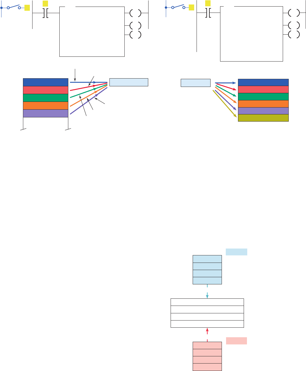
times. Other types of data manipulation used with le in-
structions include word-to- le and le-to-word moves, as
illustrated in Figure10-9 .
Files allow large amounts of data to be scanned quickly
and are useful in programs requiring the transfer, com-
parison, or conversion of data. Most PLC manufacturers
display le instructions in block format on the program-
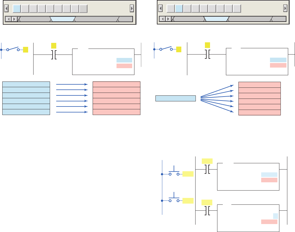
ming terminal screen. Figure 10-10 compares the SLC
Figure 10-7 Move instruction used to change the preset time of a timer.
T4:1
1.0
0
0
DN
EN
TON
TIMER ON DELAY
Timer
Time base
Preset
Accumulated
Ladder logic program
L1
PB1
PL1
L2
Output
PB1
SS1
SS1
SS1
5 s10 s
Inputs
N7:1
10
T4:1.PRE
0
MOV
MOVE
Source
Destination
N7:2
5
T4:1.PRE
0
MOV
MOVE
Source
Destination
T4:/DN
1
2
3
4
PL1
pet10882_ch10_200-225.indd 204pet10882_ch10_200-225.indd 204 7/27/10 10:45 PM7/27/10 10:45 PM
Data Manipulation Instructions Chapter 10 205
500 controller word and le addressing. The addressing
formats can be summarized as follows:
• The address that de nes the beginning of a le or
group of words starts with the pound sign #.
• The # pre x is omitted in a single word or element
address.
• Address N7:30 is a word address that represents a
single word: word number 30 in integer le 7.
• Address #N7:30 represents the starting address of
a group of consecutive words in integer le 7. The
length is eight words, which is determined by the
instruction where the le address is used.
Figure 10-8 Move instruction used to change the preset count of a counter.
L1
LS1
A
C
B
Inputs
Reset
C5:1
0
0
DN
CU
CTU
COUNT UP
Counter
Preset
Accumulated
Ladder logic program
N7:1
300
C5:1.PRE
0
MOV
MOVE
Source
Destination
Full
N7:2
175
C5:1.PRE
0
MOV
MOVE
Source
Destination
N7:3
50
C5:1.PRE
0
MOV
MOVE
Source
Destination
C5:1/DN
C5:1
RES
1
2
3
4
5
6
LS1
A
C
B
Reset
L2
Output
Full
Figure 10-9 Moving data using fi le instructions.
Word-to-file move
File
Word Word
File File File
File-to-word move
File-to-file move
pet10882_ch10_200-225.indd 205pet10882_ch10_200-225.indd 205 7/27/10 10:45 PM7/27/10 10:45 PM
206 Chapter 10 Data Manipulation Instructions
The le arithmetic and logic (FAL) instruction is used
to copy data from one le to another and to do le math
and le logic. This instruction is available only on Allen-
Bradley PLC-5 and ControlLogix platforms. An example
of the FAL instruction is shown in Figure10-11 .
The basic operation of the FAL instruction is similar
in all functions and requires the following parameters and
PLC-5 addresses to be entered in the instruction:
Control
• Is the rst entry and the address of the control struc-
ture in the control area (R) of processor memory.
• The processor uses this information to run the
instruction.
• The default le for the control le is data le 6.
• The control element for the FAL instruction must be
unique for that instruction and may not be used to
control any other instruction.
• The control element is made up of three words.
• The control word uses four control bits: bit 15
(enable bit), bit 13 (done bit), bit 11 (error bit), and
bit 10 (unload bit).
Length
• Is the second entry and represents the le length.
• This entry will be in words, except for the
floating-point file, for which the length is in
elements. (A floating-point element consists of
two words.)
• The maximum length possible is 1000 elements.
Enter any decimal number from 1 to 1000.
Position
• Is the third entry and represents the current location
in the data block that the processor is accessing.
• It points to the word being operated on.
• The position starts with 0 and indexes to 1 less than
the le length.
• You generally enter a 0 to start at the beginning of
a le. You may also enter another position at which
you want the FAL to start its operation.
• When the instruction resets, however, it will reset
the position to 0.
• You can manipulate the position from the program.
Mode
• Is the fourth entry and represents the number of le
elements operated on per program scan. There are
three choices: all mode, numeric mode, and incre-
mental mode.
All Mode
• For this mode you enter the letter A.
• In the all mode, the instruction will transfer the
complete le of data in one scan.
• The enable (EN) bit will go true when the instruc-
tion goes true and will follow the rung condition.
• When all of the data have been transferred, the done
(DN) bit will go true. This change will occur on the
same scan during which the instruction goes true.
• If the instruction does not go to completion due to an
error in the transfer of data (such as trying to store
too large or too small a number for the data-table
Figure 10-10 SLC 500 word and fi le address.
Integer Table
15 14 13 12 11 10 9 8 7 6 5 4 3 2 1 0
N7:30/ 0 0 0 0 0 0 0 0 0 0 0 0 0 0 0 0
N7:31/ 0 0 0 0 0 0 0 0 0 0 0 0 0 0 0 0
N7:32/ 0 0 0 0 0 0 0 0 0 0 0 0 0 0 0 0
N7:33/ 0 0 0 0 0 0 0 0 0 0 0 0 0 0 0 0
N7:34/ 0 0 0 0 0 0 0 0 0 0 0 0 0 0 0 0
N7:35/ 0 0 0 0 0 0 0 0 0 0 0 0 0 0 0 0
N7:36/ 0 0 0 0 0 0 0 0 0 0 0 0 0 0 0 0
N7:37/ 0 0 0 0 0 0 0 0 0 0 0 0 0 0 0 0
Radix: Table:
N7: Integer
File
#N7:30
Length = 8
N7:37
Word
N7:30
Binary
Figure 10-11 File arithmetic/logic (FAL) instruction.
EN
DN
ER
FAL
File arith/logical
Control
Length
Position
Mode
Destination
Expression
pet10882_ch10_200-225.indd 206pet10882_ch10_200-225.indd 206 7/27/10 10:45 PM7/27/10 10:45 PM
Data Manipulation Instructions Chapter 10 207
type), the instruction will stop at that point and set
the error (ER) bit. The scan will continue, but the in-
struction will not continue until the error bit is reset.
• If the instruction goes to completion, the enable bit
and the done bit will remain set until the instruction
goes false, at which point the position, the enable
bit, and the done bit will all be reset to 0.
Numeric Mode
• For this mode you enter a decimal number (1–1000).
• In the numeric mode, the le operation is distributed
over a number of program scans.
• The value you enter sets the number of elements to
be transferred per scan.
• The numeric mode can decrease the time it takes
to complete a program scan. Instead of waiting for
the total le length to be transferred in one scan, the
numeric mode breaks up the transfer of the le data
into multiple scans, thereby cutting down on the in-
struction execution time per scan.
Incremental mode
• For this mode you enter the letter I.
• In the incremental mode, one element of data is
operated on for every false-to-true transition of the
instruction.
• The rst time the instruction sees a false-to-true
transition and the position is at 0, the data in the rst
element of the le are operated on. The position will
remain at 0 and the UL bit will be set. The EN bit
will follow the instruction’s condition.
• On the second false-to-true transition, the position
will index to 1, and data in the second word of the
le will be operated on.
• The UL bit controls whether the instruction will
operate just on data in the current position, or
whether it will index the position and then trans-
fer data. If the UL bit is reset, the instruction—on
a false-to-true transition of the instruction—will
operate on the data in the current position and set
the UL bit. If the UL bit is set, the instruction—on
a false-to-true transition of the instruction—will
index the position by 1 and operate on the data in
their new position.
Destination
• Is the fth entry and is the address at which the pro-
cessor stores the result of the operation.
• The instruction converts to the data type speci ed
by the destination address.
• It may be either a le address or an element address.
Expression
• Is the last entry and contains addresses, program
constants, and operators that specify the source of
data and the operations to be performed.
• The expression entered determines the function of
the FAL instruction.
• The expression may consist of le addresses, ele-
ment addresses, or a constant and may contain only
one function because the FAL instruction may per-
form only one function.
Figure 10-12 shows an example of a le-to- le copy
function using the FAL instruction. The operation of the
program can be summarized as follows:
• When input A goes true, data from the expression
le #N7:20 will be copied into the destination le
#N7:50.
• The length of the two les is set by the value en-
tered in the control element word R6:1.LEN.
• In this instruction, we have also used the ALL
mode, which means all of the data will be trans-
ferred in the rst scan in which the FAL instruction
sees a false-to-true transition.
• The DN bit will also come on in that scan unless an
error occurs in the transfer of data, in which case the
ER bit will be set, the instruction will stop operation
at that position, and then the scan will continue at
the next instruction.
Figure 10-12 File-to-fi le copy function using the FAL
instruction.
EN
DN
ER
FAL
FILE ARITH/LOGICAL
Control
Length
Position
Mode
Destination
Expression
R6:1
6
0
All
#N7:50
528
#N7:20
L1
A
Input
Ladder logic program
528
621
778
986
342
135
N7:20
File
N7:25
528
621
778
986
342
135
N7:50
Destination
#N7:50
Expression
#N7:20
N7:55
A
pet10882_ch10_200-225.indd 207pet10882_ch10_200-225.indd 207 7/27/10 10:45 PM7/27/10 10:45 PM
208 Chapter 10 Data Manipulation Instructions
Figure10-13 shows an example of a le-to-word copy
function using the FAL instruction. The operation of the
program can be summarized as follows:
• With each false-to-true rung transition of input A,
the processor reads one word of integer le N29.
• The processor starts reading at word 0, and writes
the image into word 5 of integer le N29.
• The instruction writes over any data in the
destination.
Figure10-14 shows an example of a word-to- le copy
function using the FAL instruction. It is similar to the le-
to-word copy function except that the instruction copies
data from a word address into a le. The operation of the
program can be summarized as follows:
• The expression is a word address (N7:100) and the
destination is a le address (#N7:101).
• If we start with position 0, the data from N7:100
will be copied into N7:101 on the rst false-to-true
transition of input A .
• The second false-to-true transition of input A will
copy the data from N7:100 into N7:102.
• On successive false-to-true transitions of the instruc-
tion, the data will be copied into the next position in
the le until the end of the le, N7:106, is reached.
The exceptions to the rule that le addresses must take
consecutive words in the data table are in the timer, counter,
and control data les for the FAL instruction. In these three
data les, if you designate a le address, the FAL instruc-
tion will take every third word in that le and make a le of
preset, accumulated, length, or position data within the cor-
responding le type. This might be done, for example, so
that recipes storing values for timer presets can be moved
into the timer presets, as illustrated in Figure10-15 .
The le copy (COP) instruction and the ll le (FLL)
instruction are high-speed instructions that operate more
quickly than the same operation with the FAL instruc-
tion. Unlike the FAL instruction, there is no control ele-
ment to monitor or manipulate. Data conversion does not
Figure 10-13 File-to-word copy function using the FAL
instruction.
FAL
FILE ARITH/LOGICAL
Control
Length
Position
Mode
Destination
Expression
R6:6
5
0
INC
N29:5
#N29:0
Ladder logic program
Word 0
1
2
3
4
Word
Word N29:5
File # N29:0
First move
Second move
Fifth move
Fourth move
Third move
EN
DN
ER
L1
A
Input
A
FAL
FILE ARITH/LOGICAL
Control
Length
Position
Mode
Destination
Expression
R6:2
6
0
Incremental
#N7:101
0
N7:100
Ladder logic program
N7:101
N7:106
N7:100
First move
EN
DN
ER
L1
A
Input
A
Figure 10-14 Word-to-fi le copy function using the FAL
instruction.
Figure 10-15 Copying recipes and storing values for timer
presets.
3452
6789
8321
983
#N7:10
Length = 4
Recipe A
T4:0 preset value
T4:1 preset value
T4:2 preset value
T4:3 preset value
#T4:0.PRE
Length = 4
File of timer preset values
778
986
342
135
#N7:20
Length = 4
Recipe B
File-to-file copy
File-to-file copy
pet10882_ch10_200-225.indd 208pet10882_ch10_200-225.indd 208 7/27/10 10:45 PM7/27/10 10:45 PM
Data Manipulation Instructions Chapter 10 209
take place, so the source and destination should be the
same le types. An example of the le COP instruction is
shown in Figure10-16 . The operation of the program can
be summarized as follows:
• Both the source and destination are le addresses.
• When input A goes true, the values in le N40 are
copied to le N20.
• The instruction copies the entire le length for each
scan during which the instruction is true.
An example of the ll le (FLL) instruction is shown in
Figure10-17 . It operates in a manner similar to the FAL
instruction that performs the word-to- le copy in the ALL
mode. The operation of the program can be summarized
as follows:
• When input A goes true, the value in N15:5 is cop-
ied into N20:1 through N20:6.
• Because the instruction transfers to the end of the
le, the le will be lled with the same data value in
each word.
The FLL instruction is frequently used to zero all of
the data in a le, as illustrated in the program of Fig-
ure 10-18 . The operation of the program can be summa-
rized as follows:
• Momentarily pressing pushbutton PB1 copies the
contents of le #N10:0 into le #N12:0.
• Momentarily pressing pushbutton PB2 then clears
le #N12:0.
• Note that 0 is entered for the source value.
10.3 Data Compare Instructions
Data transfer operations are all output instructions,
whereas data compare instructions are input instructions.
Data compare instructions are used to compare numerical
values. These instructions compare the data stored in two
or more words (or registers) and make decisions based on
the program instructions. Numeric values in two words
of memory can be compared for each of the basic data
compare instructions shown in Figure10-19 , depending
on the PLC.
Data comparison concepts have already been used
with the timer and counter instructions. In both these in-
structions, an output was turned on or off when the ac-
cumulated value of the timer or counter equaled its preset
Figure 10-16 File copy (COP) instruction.
N20:1
N20:2
N20:3
N20:4
N20:5
N20:6
N40:1
N40:2
N40:3
N40:4
N40:5
N40:6
COP
COPY FILE
Source
Destination
Length
#N40:1
#N20:1
6
Ladder logic program
L1
A
Input
A
COP FLL DDV SCL INT STE
File / Misc
Move/Logical
STS STD PID
File Shift/Sequencer
Prog
Location in RSLogix software
Figure 10-17 Fill fi le (FLL) instruction.
N20:1
N20:2
N20:3
N20:4
N20:5
N20:6
N15:5
COP FLL DDV SCL INT STE
File / Misc
Move/Logical
STS STD PID
File Shift/Sequencer
Prog
Location in RSLogix software
FLL
FILL FILE
Source
Destination
Length
N15:5
#N20:1
6
Ladder logic program
L1
A
Input
A
Figure 10-18 Using the FLL instruction to change all the
data in a fi le to zero.
COP
COPY FILE
Source
Destination
Length
#N10:0
#N12:0
4
Ladder logic program
FLL
FILL FILE
Source
Destination
Length
0
#N12:0
4
L1
PB1
PB2
Inputs
PB1
PB2
pet10882_ch10_200-225.indd 209pet10882_ch10_200-225.indd 209 7/27/10 10:45 PM7/27/10 10:45 PM
210 Chapter 10 Data Manipulation Instructions
value. What actually occurred was that the accumulated
numeric data in one memory word was compared to the
preset value of another memory word on each scan of the
processor. When the processor saw that the accumulated
value was equal to the preset value, it switched the output
on or off.
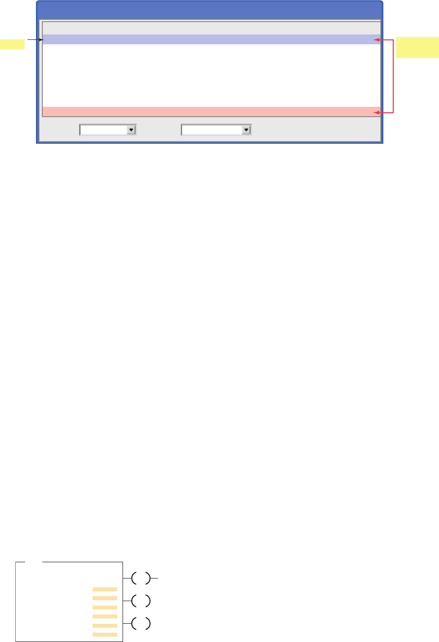
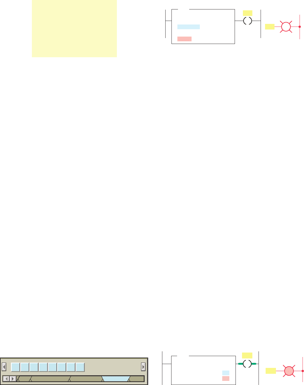
Comparison instructions are used to test pairs of val-
ues to determine if a rung is true. Figure10-20 shows the
Compare menu tab for the Allen-Bradley SLC 500 PLC
and its associated RSLogix software. The compare in-
structions can be summarized as follows:
LIM (Limit test) —Tests whether one value is within
the limit range of two other values.
MEQ (Masked Comparison for Equal) —Tests
portions of two values to see whether they are equal.
Compares 16-bit data of a source address to 16-bit
data at a reference address through a mask.
EQU (Equal) —Tests whether two values are equal.
NEQ (Not Equal) —Tests whether one value is not
equal to a second value.
LES (Less Than) —Tests whether one value is less
than a second value.
GRT (Greater Than) —Tests whether one value is
greater than a second value.
LEQ (Less Than or Equal) —Tests whether one
value is less than or equal to a second value.
GEQ (Greater Than or Equal) —Tests whether one
value is greater than or equal to a second value.
The equal (EQU) instruction is an input instruction that
compares source A to source B: when source A is equal
to source B, the instruction is logically true; otherwise it
is logically false. Figure10-21 shows an example of an
EQU logic rung. The operation of the rung can be sum-
marized as follows:
• When the accumulated value of counter T4:0 stored
in source A ’s address equals the value in source B ’s
address, N7:40, the instruction is true and the output
is energized.
• Source A may be a word address or a oating-point
address.
• Source B may be a word address, a oating-point
address, or a constant value.
• With the equal instruction, the oating-point data
is not recommended because of the exactness re-
quired. One of the other comparison instructions,
such as the limit test, is preferred.
The not equal (NEQ) instruction is an input instruction
that compares source A to source B: when source A is not
equal to source B, the instruction is logically true; other-
wise it is logically false. Figure10-22 shows an example
of an NEQ logic rung. The operation of the rung can be
summarized as follows:
• When the value stored at source A ’s address, N7:5,
is not equal to 25, the output will be true; otherwise,
the output will be false.
• The value stored at Source A is 30.
• The value stored at Source B is 25.
• Since the two values are not the same the output
will be true or on.
•
In all input-comparison instructions, Source A must
be an address and Source B can be an address or a
constant.
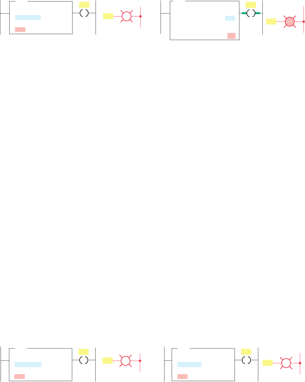
Figure 10-19 Basic PLC data compare instructions.
Name
Equal to
Not equal to
Less than
Greater than
Less than or equal to
Greater than or equal to
Symbol
(⫽)
(苷)
(⬍)
(⬎)
(ⱕ)
(ⱖ)
Figure 10-21 EQU logic rung.
L2
Ladder logic program
PL1
PL1
EQU
EQUAL
Source A
T4:0.ACC
Source B
N7:40
Output
Figure 10-22 NEQ logic rung.
L2
OutputLadder logic program
PL1
PL1
N7:5
30
25
NEQ
NOT EQUAL
Source A
Source B
Figure 10-20 Compare menu tab.
LIM MEQ EQU NEQ LES GRT
Compare
Bit
Input/OutputTimer/Counter
LEQ GEQ
Com
pet10882_ch10_200-225.indd 210pet10882_ch10_200-225.indd 210 7/27/10 10:45 PM7/27/10 10:45 PM
Data Manipulation Instructions Chapter 10 211
The greater than (GRT) instruction is an input instruc-
tion that compares source A to source B: when source A
is greater than source B, the instruction is logically true;
otherwise it is logically false. Figure10-23 shows an ex-
ample of a GRT logic rung. The operation of the rung can
be summarized as follows:
• The instruction is either true or false, depending on
the values being compared.
• When the accumulated value of timer T4:10, stored
at the address of source A, is greater than the con-
stant 200 of source B, the output will be on; other-
wise the output will be off.
The less than (LES) instruction is an input instruction
that compares source A to source B: when source A is less
than source B, the instruction is logically true; otherwise
it is logically false. Figure10-24 shows an example of an
LES logic rung. The operation of the rung can be sum-
marized as follows:
• The instruction is either true or false, depending on
the values being compared.
• When the accumulated value of counter C5:10,
stored at the address of source A, is less than the
constant 350 of source B, the output will be on; oth-
erwise, it will be off.
The greater than or equal (GEQ) instruction is an input
instruction that compares source A to source B: when
source A is greater than or equal to source B, the instruc-
tion is logically true; otherwise it is logically false. Fig-
ure10-25 shows an example of a GEQ logic rung. The
operation of the rung can be summarized as follows:
• When the value stored at the address of source A,
N7:55, is greater than or equal to the value stored at
the address of source B, N7:12, the output will be
true; otherwise, it will be false.
• The value stored at source A is 100.
• The value stored at source B is 23.
• Therefore the output will be true or on.
The less than or equal (LEQ) instruction is an input
instruction that compares source A to source B: when
source A is less than or equal to source B, the instruction
is logically true; otherwise it is logically false. Figure10-26
shows an example of an LEQ logic rung. The operation of
the rung can be summarized as follows:
• When the accumulated count of counter C5:1 is less
than or equal to 457, the pilot light will turn on.
• The accumulated value of the counter is less
than 457.
• Therefore the output will be false or off.
The limit test (LIM) instruction is used to test whether
values are within or outside the speci ed range. Applica-
tions in which the limit test instruction is used include
allowing a process to operate as long as the temperature is
within or outside a speci ed range.
Programming the LIM instruction consists of entering
three parameters: lo
w limit, test, and high limit. The limit
test instruction functions in the following two ways:
• The instruction is true if —The lower limit is equal
to or less than the higher limit, and the test param-
eter value is equal to or inside the limits. Otherwise
the instruction is false.
• The instruction is true if —The lower limit has a
value greater than the higher limit, and the instruc-
tion is equal to or outside the limits. Otherwise the
instruction is false.
Figure 10-23 GRT logic rung.
Ladder logic program
GRT
GREATER THAN
Source A
T4:10.ACC
Source B
200
L2
Output
PL1
PL1
Figure 10-24 LES logic rung.
Ladder logic program
LES
LESS THAN
Source A
C5:10.ACC
Source B
350
L2
Output
PL1
PL1
Figure 10-25 GEQ logic rung.
Ladder logic program
GEQ
GREATER THAN OR EQUAL
Source A
Source B
N7:55
100
N7:12
23
L2
Output
PL1
PL1
Ladder logic program
LEQ
LESS THAN OR EQUAL
Source A
C5:1.ACC
Source B
457
L2
Output
PL1
PL1
Figure 10-26 LEQ logic rung.
pet10882_ch10_200-225.indd 211pet10882_ch10_200-225.indd 211 7/27/10 10:45 PM7/27/10 10:45 PM
212 Chapter 10 Data Manipulation Instructions
The limit test instruction is said to be circular because
it can function in either of two ways. Figure10-27 shows
an example of an LIM instruction where the low limit
value is less than the high limit value. The operation of the
logic rung can be summarized as follows:
• The high limit has a value of 50, and the low limit
has a value of 25.
• Instruction is true for values of the test from 25
through 50.
• Instruction is false for test values less than 25 or
greater than 50.
• Instruction is true because the test value is 48.
Figure10-28 shows an example of an LIM instruction
where the low limit value is greater than the high limit
value. The operation of the logic rung can be summarized
as follows:
• The high limit has a value of 50, and the low limit
has a value of 100.
• Instruction is true for test values of 50 and less than
50 and for test values of 100 and greater than 100.
• Instruction is false for test values greater than 50
and less than 100.
• Instruction is true because the test value is 125.
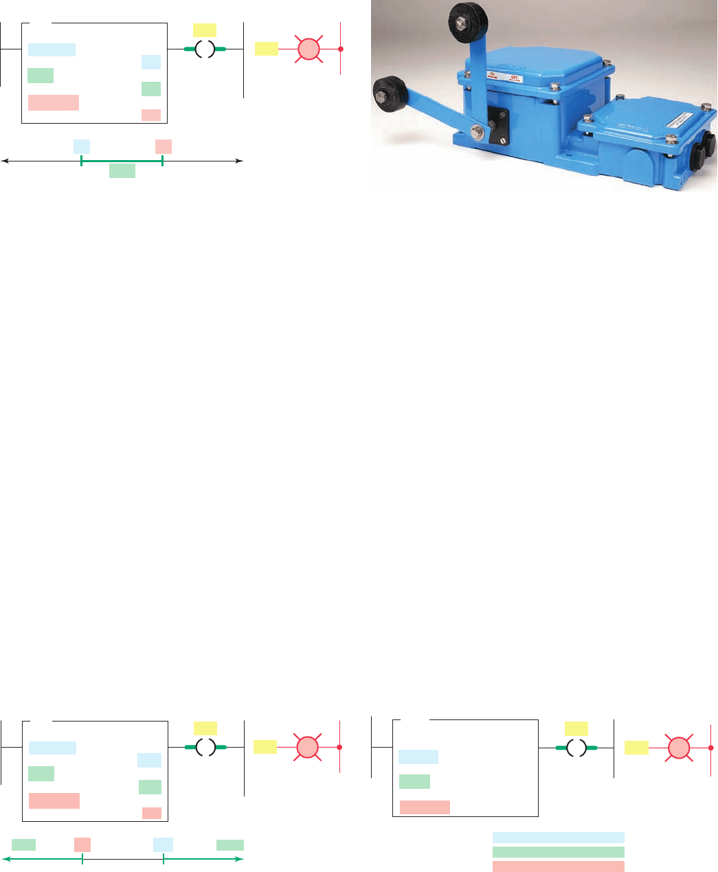
The masked comparison for equal (MEQ) instruction
compares a value from a source address with data at a com-
pare address and allows portions of the data to be masked.
One application for the MEQ instruction is to compare
the correct position of up to 16 limit switches when the
source contains the limit switch address and the compare
stores their desired states. The mask can block out the
switches you don’t want to compare ( Figure10-29 ).
Figure 10-30 shows an example of an MEQ instruc-
tion. The operation of the logic rung can be summarized
as follows:
• When the data at the source address match the data
at the compare address bit-by-bit (less masked bits),
the instruction is true.
• The instruction goes false as soon as it detects a
mismatch.
• A mask passes data when the mask bits are set (1); a
mask blocks data when the mask bits are reset (0).
True ( 50)
( 100) True
Ladder logic program
LIM
LIMIT TEST (CIRC)
Low limit
Test
High limit
N7:28
100
N7:29
125
N7:27
50
50
False
100
L2
Output
PL1
PL1
Figure 10-28 LIM instruction where the low limit value is
greater than the high limit value.
Figure 10-29 MEQ instruction can be used to monitor the
state of limit switches.
Source: Courtesy Jayashree Electrodevices.
Ladder logic program
LIM
LIMIT TEST (CIRC)
Low limit
Test
High limit
N7:22
25
N7:23
48
N7:24
50
25
False (< 25)
False (> 50)
Tr ue
50
L2
Output
PL1
PL1
Figure 10-27 LIM instruction where the low limit value is
less than the high limit value.
Ladder logic program
MEQ
MASKED EQUAL
Source
Mask
Compare
N7:5
N7:6
N7:10
Source N7:5 01010101 01011111
Mask N7:6 11111111
Compare
N7:10 01010101 0101xxxx
11110000
L2
Output
PL1
PL1
Figure 10-30 Masked comparison for equal (MEQ) logic
rung.
pet10882_ch10_200-225.indd 212pet10882_ch10_200-225.indd 212 7/27/10 10:45 PM7/27/10 10:45 PM