Petruzella F.D. Programmable Logic Controllers
Подождите немного. Документ загружается.

Math Instructions Chapter 11 233
• The following conversion formula forms the basis
for the program:
F 5
(
9
__
5
× C
)
1 32
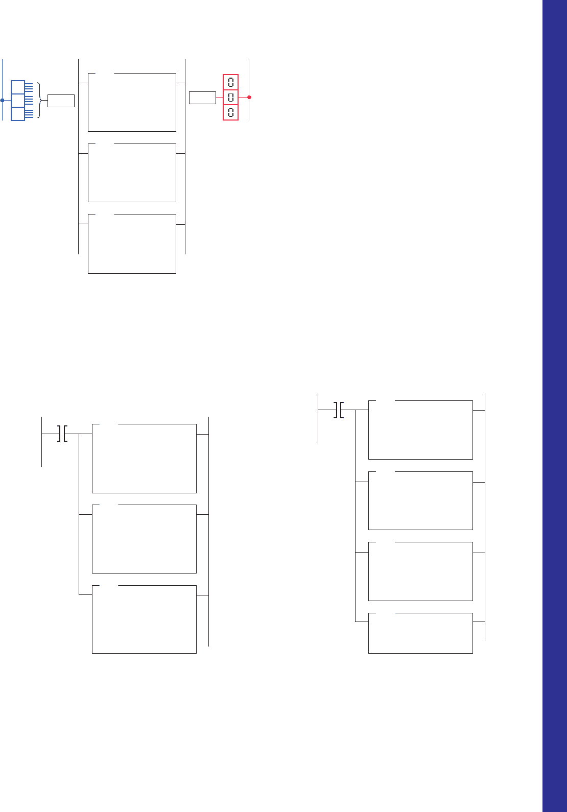
• In this example, a current temperature reading of
60°C is assumed.
• The MUL instruction multiplies the temperature
(60°C) by 9 and stores the product (540) in address
N7:0.
• Next, the DIV instruction divides 5 into the 540 and
stores the answer (108) in address N7:1.
• Finally, the ADD instruction adds 32 to the value of
108 and stores the sum (140) in address O:13.
• Thus 60°C 5 140°F.
11. 6 Other Word-Level Math
Instructions
The program of Figure11-14 is an example of the square
root (SQR) instruction. The operation of the logic rung
can be summarized as follows:
• When input switch SW is closed the SQR instruc-
tion is executed.
• The number whose square root we want to deter-
mine (144) is placed in the source.
• The function calculates the square root and places it
(12) in the destination.
• If the value of the source is negative, the instruction
will store the square root of the absolute (positive)
value of the source at the destination.
Figure 11-12 DIV instruction used to calculate the value that results
from dividing source A by source B.
Ladder logic program
OutputInput
L2
PL1
DIV
DIVIDE
Source A
Source B
Destination
N7:0
120
N7:1
4
N7:5
30
EQU
EQUAL
Source A
Source B
N7:5
30
30
PL1
L1
SW
SW
Ladder logic programInput
Thumbwheel
switch
L1
1
2
3
Output
MUL
MULTIPLY
Source A
Source B
Destination
Ι:012
60
9
N7:0
540
DIV
DIVIDE
Source A
Source B
Destination
N7:0
540
5
N7:1
108
ADD
ADD
Source A
Source B
Destination
N7:1
108
32
O:013
140
Ι:012
O:013
0 6 0
L2
LED
Display
FahrenheitCelsius
14 0
Figure 11-13 Program for converting Celsius temperature
to Fahrenheit.
Figure 11-14 SLC 500 SQR (square root) instruction.
Ladder logic program Input
L1
SQR
SQUARE ROOT
Source A
Destination
N7:101
144
N7:105
12
SW
SW
( 144 = 12)
√
pet10882_ch11_226-241.indd 233pet10882_ch11_226-241.indd 233 7/27/10 4:10 PM7/27/10 4:10 PM
234 Chapter 11 Math Instructions
Figure11-17 is an example of the TOD instruction. The
operation of the logic rung can be summarized as follows:
• When input switch SW is closed the TOD instruc-
tion is executed.
• The binary bit pattern at the source address N7:23 is
converted into a BCD bit pattern of the same deci-
mal value at the destination address O:20.
• The source displays the value 10, which is the
correct decimal value; however, the destination
displays the value 16.
• The processor interprets all bit patterns as binary;
therefore the value 16 is the binary interpretation of
the BCD bit pattern.
• The bit pattern for 10 BCD is the same as the bit
pattern for 16 binary.
The convert from BCD (FRD) instruction is used to con-
vert binary-coded decimal (BCD) values to integer values.
This instruction could be used to convert data from a BCD
external source, such as a BCD thumbwheel switch, to the
binary format in which the processor operates. The program
of Figure11-18 is an example of the FRD instruction. The
operation of the logic rung can be summarized as follows:
• When input switch SW is closed the FDR instruc-
tion is executed.
• The BCD bit pattern stored at the source address
I:30 is converted into a binary bit pattern of the same
decimal value at the destination address, N7:24.
The program of Figure 11-15 is an example of the
negate (NEG) instruction. This math function changes
the sign of the source value from positive to negative.
The operation of the logic rung can be summarized as
follows:
• When input switch SW is closed the NEG instruc-
tion is executed.
• The positive value 101 stored at the source address
N7:52 is negated to 2101 and stored in destination
address N7:53.
• Positive numbers will be stored in straight binary
format, and negative numbers will be stored as 2’s
complement.
The program of Figure11-16 is an example of the clear
(CLR) instruction. The operation of the logic rung can be
summarized as follows:
• When input switch SW is closed the CLR instruc-
tion is executed.
• Upon execution it sets all bits of a word to zero.
• In this example it changes the value of all bits stored
in the destination address N7:22 to 0.
The convert to BCD (TOD) instruction is used to
convert 16-bit integers into binary-coded decimal
(BCD) values. This instruction could be used when
transferring data from the processor (which stores data
in binary format) to an external device, such as an LED
display, that functions in BCD format. The program of
Figure 11-15 SLC 500 NEG (negate) instruction.
Ladder logic program Input
L1
NEG
NEGATE
Source A
Destination
N7:52
101
N7:53
–101
SW
SW
Figure 11-16 SLC 500 CLR (clear) instruction.
N7:22
0000000000000000
Ladder logic program Input
L1
CLR
CLEAR
Destination
SW
SW
Ladder logic program Input
L1
TOD
TO BCD
Source
Destination
N7:23
10
O:20
16
SW
SW
Figure 11-17 SLC 500 TOD (convert to BCD) instruction.
Figure 11-18 SLC 500 FRD (convert from BCD)
instruction.
Ladder logic program Input
L1
FRD
FROM BCD
Source
Destination
I:30
16
N7:24
10
SW
SW
pet10882_ch11_226-241.indd 234pet10882_ch11_226-241.indd 234 7/27/10 4:10 PM7/27/10 4:10 PM
Math Instructions Chapter 11 235
data in le address N7:25 to the data stored in le
address N7:50 and store the result in le address
N7:100.
• The rate per scan is set at All, so the instruction
goes to completion in one scan.
The program of Figure11-21 is an example of the le
subtract function of the FAL instruction. The operation of
the logic rung can be summarized as follows:
• When input switch SW is closed the rung goes true
and the processor subtracts a program constant
(255) from each word of le address N10:0 and
The scale data (SCL) instruction is used to allow very
large or very small numbers to be enlarged or reduced by
the rate value. When rung conditions are true, this instruc-
tion multiplies the source by a speci ed rate. The rounded
result is then added to an offset value and placed in the
destination. The program of Figure11-19 is an example
of the SCL instruction. The operation of the logic rung
can be summarized as follows:
• When input switch SW is closed the SCL instruc-
tion is executed.
• The number 100 stored at the source address, N7:0,
is multiplied by 25,000, divided by 10,000, and
added to 127.
• The result, 377, is placed in the destination address,
N7:1.
You can use SCL instruction to scale data from your
analog module and bring it into the limits prescribed by the
process variable or another analog module. For instance,
you can use the SCL instruction to convert a 4–20 mA
input signal to a PID process variable, or to scale an ana-
log input to control an analog output.
11.7 File Arithmetic Operations
File arithmetic functions include le add, le subtract,
le multiply, le divide, le square root, le convert from
BCD, and le convert to BCD. The le arithmetic and
logic (FAL) instruction can combine an arithmetic opera-
tion with le transfer. The arithmetic operations that can
be implemented with the FAL are ADD, SUB, MULT,
DIV, and SQR.
The le add function of the FAL instruction can be
used to perform addition operations on multiple words.
The program of Figure11-20 is an example of the le add
function of the FAL instruction. The operation of the logic
rung can be summarized as follows:
• When input switch SW is closed the rung goes true
and the expression tells the processor to add the
Figure 11-19 SLC 500 SCL (scale) instruction.
Ladder logic program Input
L1
SW
SW
SCL
SCALE
Source
Rate (/10000)
Offset
Destination
N7:0
100
25000
127
N7:1
377
Ladder logic program Input
L1
SW
SW
FAL
FILE ARITH/LOGICAL
Control
Length
Position
Mode
Destination
Expression
#N7:25 + #N7:50
R6:1
4
0
All
#N7:100
25
234
1256
77
N7:25
N7:28
= N7:100
= N7:103
+ N7:50
+
+
+ N7:53
50
22
456
100
75
256
1712
177
#N7:25 #N7:50 #N7:100
EN
DN
ER
Figure 11-20 SLC 500 fi le add function of the FAL
instruction.
Figure 11-21 SLC 500 fi le subtract function of the FAL
instruction.
680
950
20
100
N10:0
N10:3
= N7:255
= N7:258
– 255 425
695
–235
–155
#N10:0 #N7:255
Ladder logic program Input
L1
SW
SW
FAL
FILE ARITH/LOGICAL
Control
Length
Position
Mode
Destination
Expression
#N10:0 – 255
R6:5
4
0
2
#N7:255
EN
DN
ER
pet10882_ch11_226-241.indd 235pet10882_ch11_226-241.indd 235 7/27/10 4:10 PM7/27/10 4:10 PM
236 Chapter 11 Math Instructions
• The rate per scan is set at All, so the instruction
goes to completion in one scan.
The program of Figure11-23 is an example of the le
divide function of the FAL instruction. The operation of
the logic rung can be summarized as follows:
• When input switch SW is closed the rung goes true
and the data in le address F8:20 is divided by the
data in le address F8:100, with the result stored in
element address F8:200.
• The mode is Incremental, so the instruction operates
on one set of elements for each false-to-true transi-
tion of the instruction.
stores the result at the destination le address,
N7:255.
• The rate per scan is set at 2, so it will take 2 scans
from the moment the instruction goes true to com-
plete its operation.
The program of Figure11-22 is an example of the le
multiply function of the FAL instruction. The operation of
the logic rung can be summarized as follows:
• When input switch SW is closed the rung goes true
and the data in le address N7:330 is multiplied by
the data in element address N7:23, with the result
stored at the destination le address N7:500.
Figure 11-22 SLC 500 fi le multiply function of the FAL
instruction.
20
240
–78
321
N7:330
N7:333
= N7:500
= N7:503
N7:23 100
*
2000
24000
–7800
32100
#N7:330 #N7:500N7:23
Ladder logic program Input
L1
SW
SW
FAL
FILE ARITH/LOGICAL
Control
Length
Position
Mode
Destination
Expression
#N7:330
*
N7:23
R6:8
4
0
All
#N7:500
EN
DN
ER
Figure 11-23 SLC 500 fi le divide function of the FAL
instruction.
Ladder logic program Input
L1
SW
SW
FAL
FILE ARITH/LOGICAL
Control
Length
Position
Mode
Destination
Expression
#F8:20 / #F8:100
R6:7
4
1
Incremental
F8:200
100
25
1.33
586
F8:20
F8:23
= F8:200÷ F8:100
F8:103
1000
2
1.5
3
0.1
#F8:20 #F8:100 F8:200
EN
DN
ER
pet10882_ch11_226-241.indd 236pet10882_ch11_226-241.indd 236 7/27/10 4:10 PM7/27/10 4:10 PM
Math Instructions Chapter 11 237
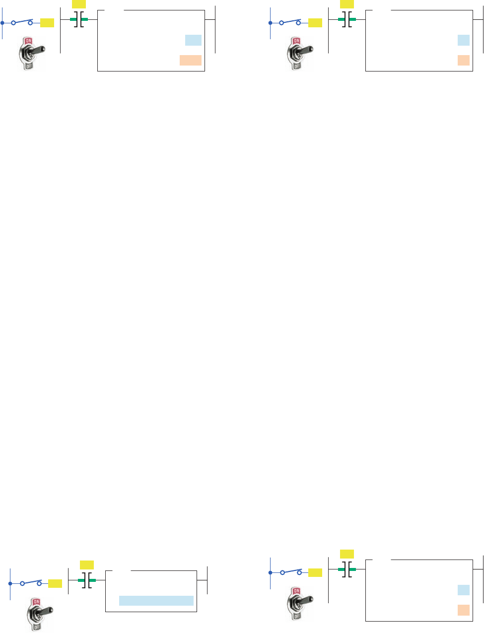
1. Explain the function of math instructions as applied
to the PLC.
2. Name the four basic math functions performed by
PLCs.
3. What standard format is used for PLC math
instructions?
4. Would math instructions be classi ed as input or
output instructions?
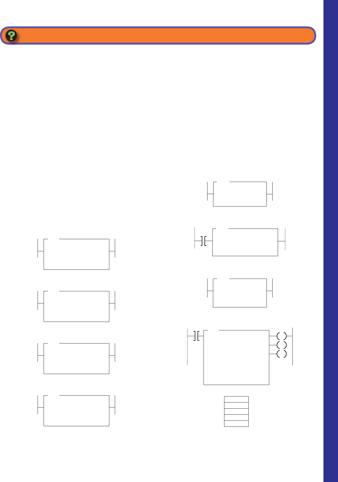
5. With reference to the instruction of Figure11-24 ,
what is the value of the number stored at source B
if N7:3 contains a value of 60 and N7:20 contains a
value of 80?
6. With reference to the instruction of Figure11-25 ,
what is the value of the number stored at the desti-
nation if N7:3 contains a value of 500?
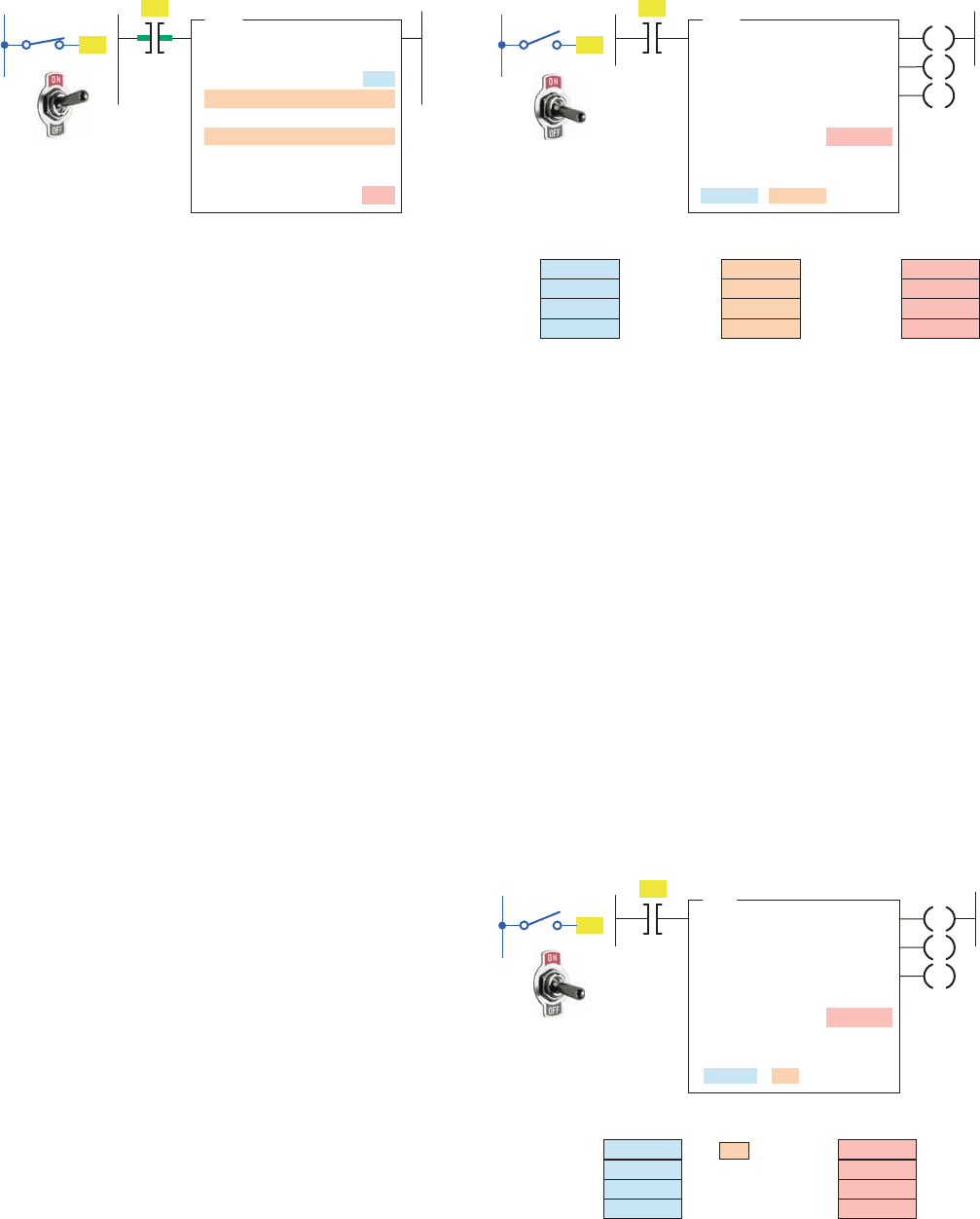
7. With reference to the instruction of Figure11-26 ,
what is the value of the number stored at the des-
tination if N7:3 contains a value of 40 and N7:4
contains a value of 3?
8. With reference to the instruction of Figure11-27 ,
what is the value of the number stored at the
destination if N7:3 contains a value of 15 and N7:4
contains a value of 4?
9. With reference to the instruction of Figure11-28 ,
what is the value of the number stored at N7:20 if
N7:3 contains a value of 2345?
10. With reference to the instruction of Figure11-29 ,
what will be the value of each of the bits in word
B3:3 when the rung goes true?
11. With reference to the instruction of Figure11-30 ,
what is the value of the number stored at N7:101?
12. With reference to the instruction of Figure11-31 ,
list the values that will be stored in le #N7:10
when the rung goes true.
Figure 11-24 Instruction for Question 5.
ADD
ADD
Source A
Source B
Destination
N7:3
N7:4
N7:20
Figure 11-25 Instruction for Question 6.
SUB
SUBTRACT
Source A
Source B
Destination
N7:3
338
N7:20
Figure 11-26 Instruction for Question 7.
DIV
DIVIDE
Source A
Source B
Destination
N7:3
N7:4
N7:20
Figure 11-27 Instruction for Question 8.
MUL
MULTIPLY
Source A
Source B
Destination
N7:3
N7:4
N7:20
Figure 11-28 Instruction for Question 9.
NEG
NEGATE
Source
Destination
N7:3
N7:20
Figure 11-29 Instruction for Question 10.
CLR
CLEAR
Destination
B3:3
0000111100001111
Figure 11-30 Instruction for Question 11.
SQR
SQUARE ROOT
Source A
Destination
N7:101
N7:105
4
FAL
FILE ARITH/LOGICAL
Control
Length
Position
Mode
Destination
Expression
#N11:0 10
R6:0
5
0
All
#N7:10
328
150
10
32
0
File #N11:0
EN
DN
ER
Figure 11-31 Instruction for Question 12.
CHAPTER 11 REVIEW QUESTIONS
pet10882_ch11_226-241.indd 237pet10882_ch11_226-241.indd 237 7/27/10 4:10 PM7/27/10 4:10 PM
238 Chapter 11 Math Instructions
(3) N7:1
(4) Source B of the GEQ instruction
d. Will output PL1 be energized at this point?
Why?
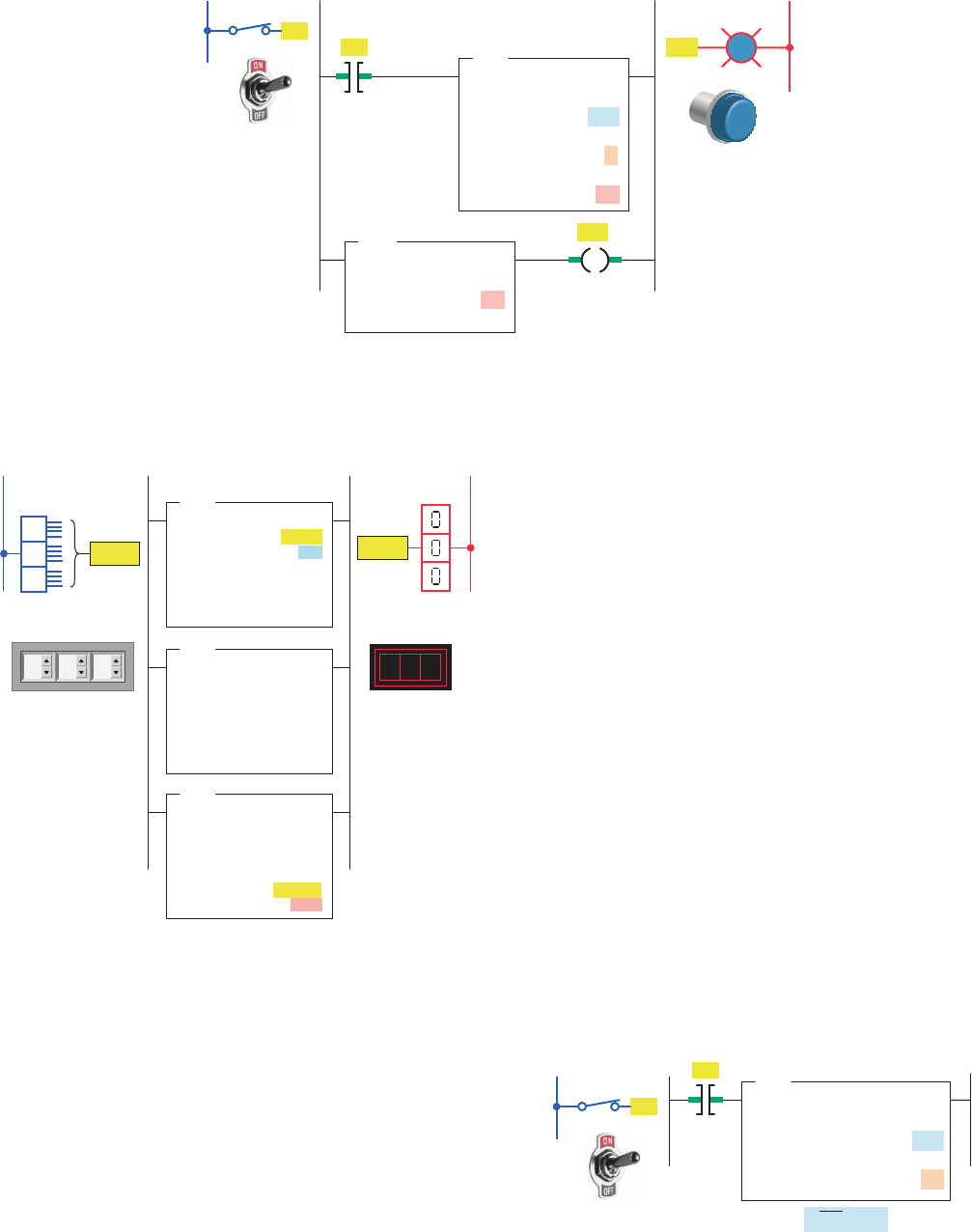
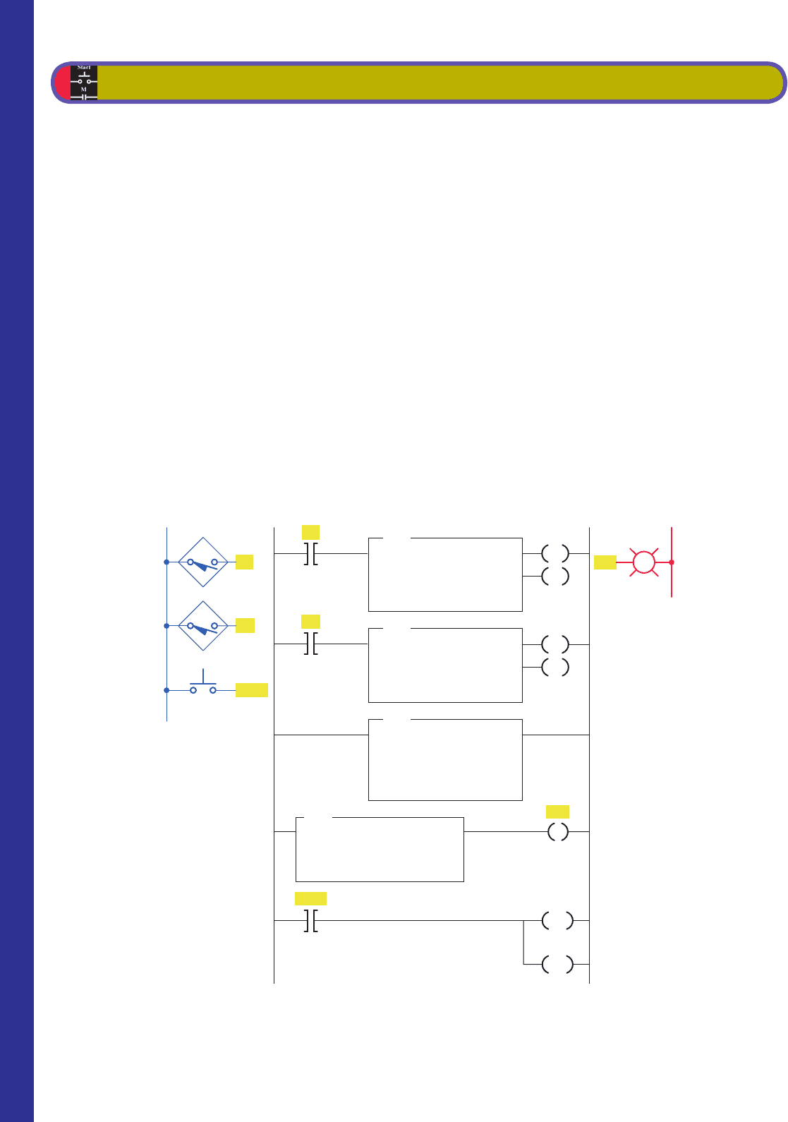
2. Answer each of the following with reference to the
over ll alarm program shown in Figure11-33 .
a. Assume that the vessel is lling and has reached
the 300-lb point. State the status of each of the
logic rungs (true or false) at this point.
b. Assume that the vessel is lling and has reached
the 480-lb point. State the value of the number
stored in each of the following words at this
point:
(1) I:012
(2) N7:1
c. Assume that the vessel is lled to a weight of
502 lb. State the status of each of the logic rungs
(true or false) for this condition.
1. Answer each of the following with reference to the
counter program shown in Figure11-32 .
a. Assume the accumulated count of counters C5:0
and C5:1 to be 148 and 36, respectively. State
the value of the number stored in each of the fol-
lowing words at this point:
(1) C5:0.ACC
(2) C5:1.ACC
(3) N7:1
(4) Source B of the GEQ instruction
b. Will output PL1 be energized at this point?
Why?
c. Assume the accumulated count of counters C5:0
and C5:1 to be 250 and 175, respectively. State
the value of the number stored in each of the fol-
lowing words at this point:
(1) C5:0.ACC
(2) C5:1.ACC
CHAPTER 11 PROBLEMS
Figure 11-32 Program for Problem 1.
L1
Inputs
S2
L2
OutputLadder logic program
S1
C5:0
350
0
CTU
COUNT-UP COUNTER
Counter
Preset
Accumulated
C5:1
350
0
CTU
COUNT-UP COUNTER
Counter
Preset
Accumulated
PL1
C5:0.ACC
C5:1.ACC
N7:1
ADD
ADD
Source A
Source B
Destination
Reset
C5:0
GEQ
GREATER THAN OR EQUAL
Source A
Source B
N7:1
350
CU
DN
CU
DN
RES
C5:1
RES
PL1
Reset
S1
S2
pet10882_ch11_226-241.indd 238pet10882_ch11_226-241.indd 238 7/27/10 4:10 PM7/27/10 4:10 PM
Math Instructions Chapter 11 239
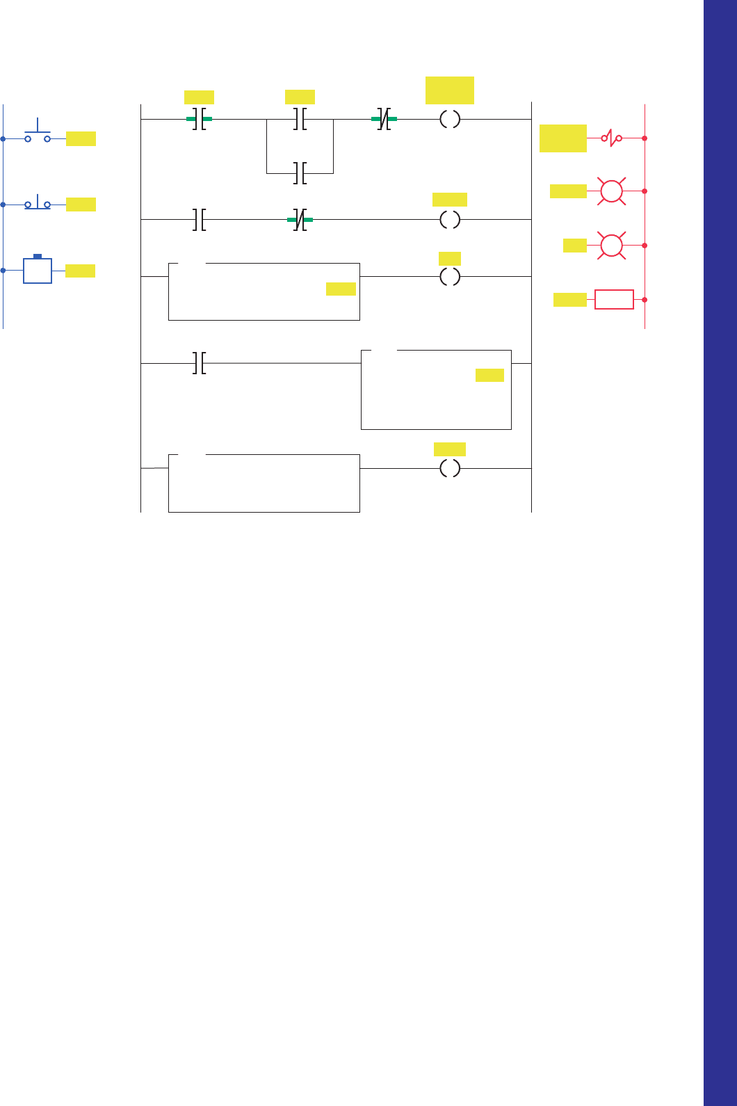
c. Assume that the set-point temperature is 600°F
and the thermocouple input module indicates a
temperature of 608°F. What is the status (energized
or not energized) of each of the following outputs?
(1) PL1
(2) PL2
(3) Heater
4. With reference to the Celsius to Fahrenheit con-
version program shown in Figure11-35 , state the
value of the number stored in each of the following
words for a thumbwheel setting of 035:
a. I:012
b. N7:0
c. N7:1
d. O:013
5. Design a program that will add the values stored
at N7:23 and N7:24 and store the result in N7:30
whenever input A is true, and then, when input B is
true, will copy the data from N7:30 to N7:31.
6. Design a program that will take the accumulated
value from TON timer T4:1 and display it on a
4-digit, BCD format set of LEDs. Use address
d. Assume that the vessel is lled to a weight of
510 lb. State the value of the number stored in
each of the following words for this condition:
(1) I:012
(2) N7:1
e. With the vessel lled to a weight of 510 lb, state
the status of each of the logic rungs (true or
false).
3. Answer the following with reference to the tem-
perature control program shown in Figure11-34 .
a. Assume that the set-point temperature is 600°F.
At what temperature will the electric heaters be
turned on and off?
b. Assume that the set-point temperature is 600°F
and the thermocouple input module indicates a
temperature of 590°F. What is the value of the
number stored in each of the following words at
this point?
(1) I:012
(2) I:013
(3) N7:0
(4) N7:1
(5) N7:2
Figure 11-33 Program for Problem 2.
Ladder logic program
Full
Fill
solenoid
Fill
solenoid
Full
Full
Filling
Outputs
L2
Inputs
L1
Weight
transducer
(All 16 bits)
SUB
SUBTRACT
Source A
Source B
Destination
GEQ
GREATER THAN OR EQUAL
Source A
Source B
GEQ
GREATER THAN OR EQUAL
Source A
Source B
N7:1
5
1
2
3
4
5
Start
Ι:012
Stop
Ι:012
500
Full
Fill
solenoid
Alarm
Start
Stop
Filling
Ι:012
500
N7:1
Fill
solenoid
Alarm
Full
Filling
pet10882_ch11_226-241.indd 239pet10882_ch11_226-241.indd 239 7/27/10 4:10 PM7/27/10 4:10 PM
240 Chapter 11 Math Instructions
• Multiply the value in N7:3 by 25 and store the
result in N7:4.
• Divide the value in N7:4 by 35 and store the
result in F8:0.
8. a. There are three part conveyor lines (1-2-3) feed-
ing a main conveyor. Each of the three conveyor
lines has its own counter. Construct a PLC pro-
gram to obtain the total count of parts on the
main conveyor.
b. Add a timer to the program that will update the
total count every 30 s.
O:023 for the LEDs. Include the provision to
change the preset value of the timer from a set of
4-digit BCD thumbwheels when input A is true.
Use address I:012 for the thumbwheels.
7. Design a program that will implement the follow-
ing arithmetic operation:
• Use a MOV instruction and place the value 45 in
N7:0 and 286 in N7:1.
• Add the values together and store the result in N7:2.
• Subtract the value in N7:2 from 785 and store the
result in N7:3.
Figure 11-34 Program for Problem 3.
Ladder logic program
ON/OFF
PL1 PL2
Heater
Heater
PL2
PL1
MUL
MULTIPLY
Source A
Source B
Destination
Ι:012
400
0.0100000
N7:0
4
ADD
ADD
Source A
Source B
Destination
Ι:012
400
N7:0
4
N7:1
404
SUB
SUBTRACT
Source A
Source B
Destination
Ι:012
400
N7:0
4
N7:2
396
LES
LESS THAN
Source A
Source B
Ι:013
0
N7:2
396
GRT
GREATER THAN
Source A
Source B
Ι:013
0
N7:1
404
Inputs
L1
ON/OFF
TWS
Thermocouple
input
1
2
3
Ι:013
Ι:012
PL1
PL2
Heater
L2
Outputs
pet10882_ch11_226-241.indd 240pet10882_ch11_226-241.indd 240 7/27/10 4:10 PM7/27/10 4:10 PM
Math Instructions Chapter 11 241
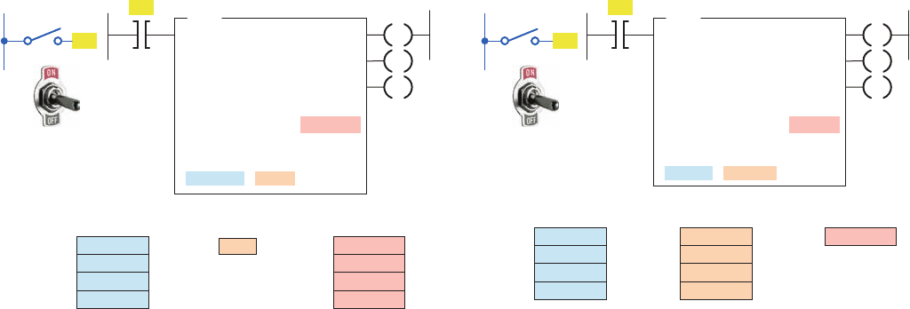
10. With reference to the math instruction program
shown in Figure11-37 , when the input goes
true, what value will be stored at each of the
following?
a. N7:3
b. N7:4
c. N7:5
d. N7:6
11. Two part conveyor lines, A and B, feed a main
conveyor line M. A third conveyor line, R,
removes rejected parts a short distance away from
the main conveyor. Conveyors A, B, and R have
parts counters connected to them. Construct a PLC
program to obtain the total parts output of main
conveyor M.
12. A main conveyor has two conveyors, A and B,
feeding it. Feeder conveyor A puts six-packs of
canned soda on the main conveyor. Feeder con-
veyor B puts eight-packs of canned soda on the
main conveyor. Both feeder conveyors have coun-
ters that count the number of packs leaving them.
Construct a PLC program to give a total can count
on the main conveyor.
9. With reference to math instruction program shown
in Figure11-36 , when the input goes true, what
value will be stored at each of the following?
a. N7:3
b. N7:5
c. F8:1
Figure 11-35 Program for Problem 4.
Ladder logic programInput
Thumbwheel
switch
L1
Celsius
Fahrenheit
1
2
3
Output
MUL
MULTIPLY
Source A
Source B
Destination
Ι:012
9
N7:0
DIV
DIVIDE
Source A
Source B
Destination
N7:0
5
N7:1
ADD
ADD
Source A
Source B
Destination
N7:1
32
O:013
Ι:012
O:013
L2
LED
Display
Figure 11-36 Program for Problem 9.
MUL
MULTIPLY
Source A
Source B
Destination
N7:3
N7:4
4
N7:5
ADD
ADD
Source A
Source B
Destination
N7:1
208
N7:2
114
N7:3
DIV
DIVIDE
Source A
Source B
Destination
N7:5
5.000000
F8:1
Input
Figure 11-37 Program for Problem 10.
Input
MUL
MULTIPLY
Source A
Source B
Destination
N7:3
2
N7:4
SUB
SUBTRACT
Source A
Source B
Destination
N7:1
80
N7:2
20
N7:3
ADD
ADD
Source A
Source B
Destination
N7:4
24
N7:5
SQR
SQUARE ROOT
Source
Destination
N7:5
N7:6
pet10882_ch11_226-241.indd 241pet10882_ch11_226-241.indd 241 7/27/10 4:10 PM7/27/10 4:10 PM
242
12
Sequencer and Shift
Register Instructions
Chapter Objectives
After completing this chapter, you will be able to:
12.1 Identify and describe the various forms of mechanical
sequencers and explain the basic operation of each
12.2 Interpret and explain information associated
with PLC sequencer output, compare, and load
instructions
12.3 Compare the operation of an event-driven and a time-
driven sequencer
12.4 Describe the operation of bit and word shift registers
12.5 Interpret and develop programs that use shift registers
This chapter explains how the PLC sequencer
and shift register functions operate and how
they can be applied to control problems. The se-
quencer instruction evolved from the mechanical
drum switch, and it can handle complex sequenc-
ing control problems more easily than does the
drum switch. Shift registers are often used to
track parts on automated manufacturing lines by
shifting either status or values through data fi les.
Image Used with Permission of Rockwell Automation, Inc.
pet10882_ch12_242-267.indd 242pet10882_ch12_242-267.indd 242 7/28/10 8:15 PM7/28/10 8:15 PM