Petruzella F.D. Programmable Logic Controllers
Подождите немного. Документ загружается.

Sequencer and Shift Register Instructions Chapter 12 243
• Each location where there was a peg is represented
by a 1 (on), and the positions where there were no
pegs are each represented by a 0 (off ).
Sequencer switches are useful whenever a repeatable
operating pattern is required. One example is the timed
12.1 Mechanical Sequencers
Sequencer instructions are designed to operate much like
the mechanical rotating cam limit switch shown in Fig-
ure 12-1 . These mechanical type sequencers are often
referred to as drum switches, rotary switches, stepper
switches, or cam switches. They are often used to control
machinery that has a repetitive cycle of operation.
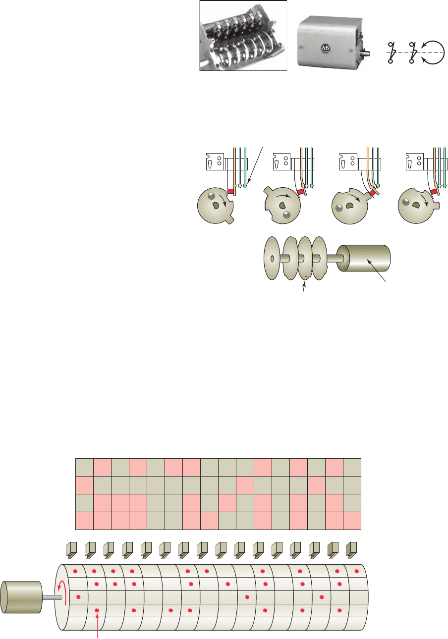
Figure12-2 illustrates the operation of a cam-operated
sequencer switch. An electric motor is used to drive the
cams. A series of leaf-spring mounted contacts interacts
with the cam so that in different degrees of rotation of the
cam, various contacts are closed and opened to energize
and de-energize various electrical devices. As the cams
rotate, load devices connected to the contacts can change
from an on to an off state, from an off to an on state, or
remain at the same state.
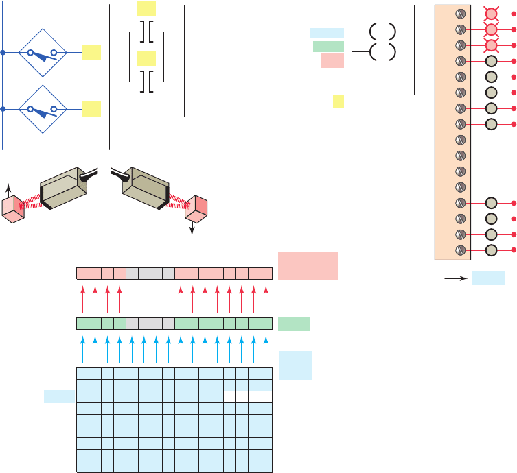
Figure 12-3 illustrates a typical mechanical drum-
operated sequencer switch. The switch consists of a series
of normally open contact blocks that are operated by pegs
located on the motor-driven drum. The operation of this
sequencer can be summarized as follows:
• Pegs are placed at speci c locations around the
circumference of the drum to operate the contact
blocks.
• When the drum is rotated, contacts that align with
the pegs will close, whereas the contacts where
there are no pegs will remain open.
• The presence of a peg can be interpreted as logic 1,
or on, and the absence of a peg as logic 0, or off.
• The equivalent sequencer data table illustrates the
logic state for the rst four steps of the drum cylinder.
Figure 12-1 Rotating cam limit switch.
Source: Image Used with Permission of Rockwell Automation, Inc.
SymbolEnclosureSwitch assembly
Figure 12-2 Mechanical cam-operated sequencer.
Motor
Contacts
Cam
Figure 12-3 Mechanical drum-operated sequencer switch.
Equivalent sequencer data table
10
1
0
0
1
1
1
2
4
1
3
0
0
11
1
0
1
0
1
0
0
1
11
1
00
0
1
0
01
0
1
01
00
0
1
0
1
10
0
0
0
0
0
1
1
00
00
0
1
0
10
0
1
10
0
1
3
1
4
2
Steps
NO
switch
Motor
Peg
pet10882_ch12_242-267.indd 243pet10882_ch12_242-267.indd 243 7/28/10 8:15 PM7/28/10 8:15 PM
244 Chapter 12 Sequencer and Shift Register Instructions
domestic washing machine is another example of the use
of a sequencer, as are dryers and similar time-clock con-
trolled devices.
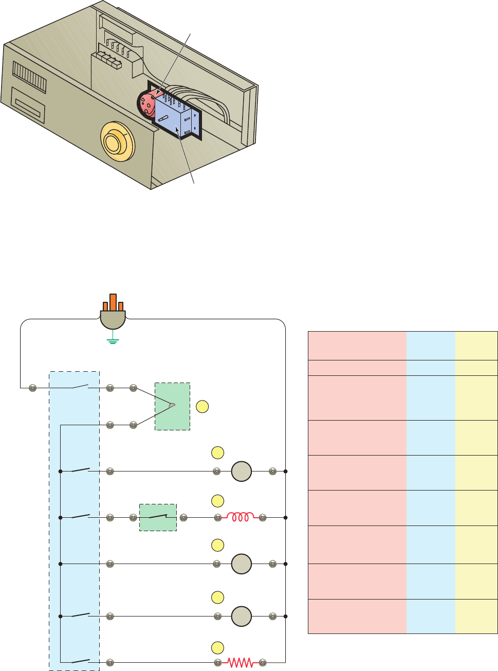
An example of the wiring and timing chart for a dish-
washer that uses a cam-operated sequencer, commonly
known as the timer, is shown in Figure12-5 . A synchro-
nous motor drives a mechanical train that, in turn, drives a
series of cam wheels. The operation of this sequencer can
be summarized as follows:
• The timer motor operates continuously throughout
the cycle of operation.
• The cam advances in time increments of 45 seconds
in duration.
• The data timing chart shows the sequence of opera-
tion of the timer.
• A total of sixty 45 second steps are used to com-
plete the 45 minute operating cycle.
• Numbers in the active devices column refer to
control devices active during each step of the
cycle.
sequencer switch used in dishwashers to pilot the ma-
chinery through a wash cycle ( Figure12-4 ). The cycle is
always the same with a xed routine of actions at each
step for a speci c time to complete its speci ed task. The
Figure 12-4 Dishwasher timed sequencer switch.
Contacts
Motor
Figure 12-5 Dishwasher wiring diagram and timing chart.
Machine function
Active
devices
Timer
increment
Off
First prerinse
Drain
Fill
Rinse
Drain
1 2 4
1 3 4 5
1 4 5 6
1 2 4 5
2
3
4–5
6
Prewash
Fill
Wash
Drain
1 3 4 5
1 4 5 6
1 2 4 5
7
8–10
11
0–1
Second prerinse
Fill
Rinse
Drain
1 3 4 5
1 4 5 6
1 2 4
12
13–15
16
Wash
Fill
Wash
Drain
1 3 4
1 4 5 6
1 2 4 5
17
18–30
31
First rinse
Fill
Rinse
Drain
1 3 4 5
1 4 5 6
1 2 4 5
32
33–34
35
Second rinse
Fill
Rinse
Drain
1 3 4 5
1 4 5 6
1 2 4 5
36
37–41
42
Dry
Dry
Drain
Dry
1 4 6
1 2 4 6
1 4 6
43–58
59
60
Ground
L1
Line
switch
L2L1
Timer
MTR
Safety water
level switch
1
Drain
pump
2
Timer
motor
4
Circulating
motor
5
Heater
6
Fill
valve
3
MTR
MTR
pet10882_ch12_242-267.indd 244pet10882_ch12_242-267.indd 244 7/27/10 4:32 PM7/27/10 4:32 PM
Sequencer and Shift Register Instructions Chapter 12 245
Parameters that may be required to be entered in se-
quencer instructions can be summarized as follows:
File —Is the starting address for the registers in the se-
quencer le and you must use the indexed le indica-
tor (#) for this address. The le contains the data that
will be transferred to the destination address when the
instruction undergoes a false-to-true transition. Each
word in the le represents a position, starting with
position 0 and continuing to the le length.
Mask —Is the bit pattern through which the sequencer
instruction moves source data to the destination ad-
dress. Recall that in the mask bit pattern, a 1 passes
values while a 0 blocks the data ow. You use a mask
register or le name when you want to change the
mask pattern under program control. An h is placed
behind the parameter to indicate that the mask is
a hexadecimal number or a B to indicate binary
notation. Decimal notation is entered without any
indicator.
Source —Is the address of the input word or le from
which the SQC and SQL instruction obtains data for
comparison or input to its sequencer le.
Destination —Is the address of the output word or le
to which the SQO moves the data from its sequencer
le.
Control —Is the address that contains the parameters
with control information for the instruction. The con-
trol register stores the status byte of the instruction,
the length of the sequencer le, and the instantaneous
position in the le as follows:
- The enable bit (EN; bit 15) is set by a false-to-true
rung transition and indicates that the instruction is
enabled. It follows the rung condition.
- The done bit (DN; bit 13) is set after the last word
in the sequencer le is transferred. On the next
false-to-true transition of the rung with the done bit
set, the position pointer is reset to 1.
- The error bit (ER; bit 11) is set when the proces-
sor detects a negative position value, or a negative
or zero length value.
12.2 Sequencer Instructions
PLC sequencer instructions replace the mechanical drum
sequencer that is used to control machines that have a
stepped sequence of repeatable operations. Programmed
sequencers can perform the same speci c on or off pat-
terns of outputs that are continuously repeated with a
drum switch, but with much more exibility. Sequencer
instructions simplify your ladder program by allowing
you to use a single instruction or pair of instructions to
perform complex operations. For example, the on/off op-
eration of 16 discrete outputs can be controlled, using a
sequencer instruction, with only one ladder rung. By con-
trast, the equivalent contact-coil ladder control arrange-
ment would need 16 rungs in the program.
Depending on the PLC manufacturer, various sequencer
instructions can be programmed. Figure 12-6 shows the
Sequencer menu tab for the Allen-Bradley SLC 500
PLC and its associated RSLogix software. For the Allen-
Bradley line of controllers, sequencer commands may
include the following:
SQO (Sequencer Output) —Is an output instruction
that uses a le to control various output devices.
SQI (Sequencer Input) —Is an input instruction that
compares bits from an input le to corresponding bits
from a source address. The instruction is true if all
pairs of bits are the same.
SQC (Sequencer Compare) —Is an output instruc-
tion that compares bits from an input source le to
corresponding bits from data words in a sequence le.
If all pairs of bits are the same, then a bit in the con-
trol register is set to 1.
SQL (Sequencer Load) —Is an output instruction
used to capture reference conditions by manually
stepping the machine through its operating sequences.
It transfers data from the input source module to the
sequencer le. The instruction functions much like a
le-to-word transfer instruction.
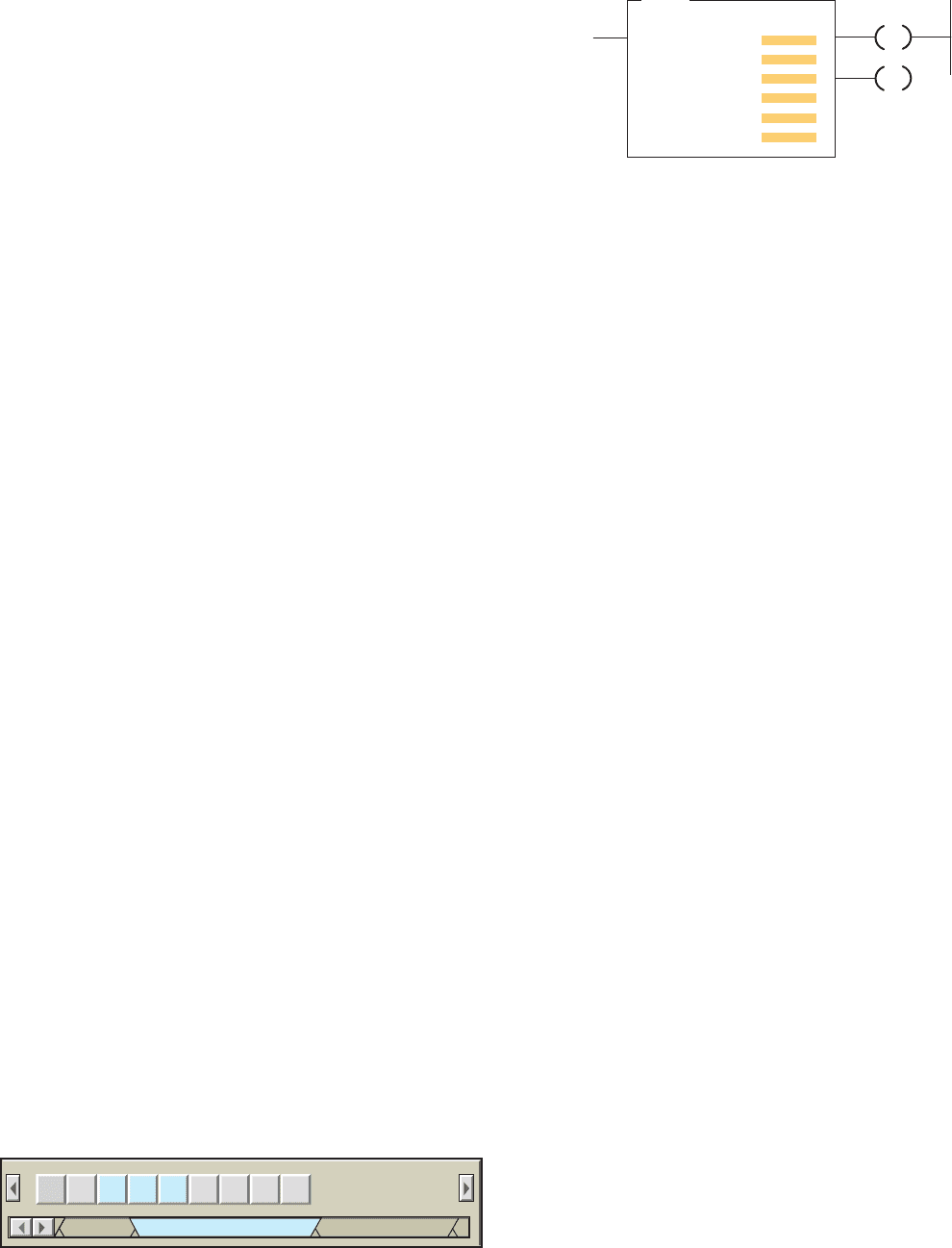
Figure12-7 shows an example of an SQO (Sequencer
Output) instruction. The SQO instruction reads data le
elements (words) one at a time, applies a mask word to
enable or disable bits from the current data le element,
and transfers the masked data le element to a designated
output.
Figure 12-6 Sequencer menu tab.
BSL BSR SQC SQL SQO FFL
File Shift / Sequencer
File/Misc Program Control
FFU LFL LFU
Figure 12-7 SQO (Sequencer Output) instruction.
SQO
SEQUENCER OUTPUT
File
Mask
Destination
Control
Length
Position
DN
EN
pet10882_ch12_242-267.indd 245pet10882_ch12_242-267.indd 245 7/27/10 4:32 PM7/27/10 4:32 PM
246 Chapter 12 Sequencer and Shift Register Instructions
Length —Is the number of steps of the sequencer le
starting at position 1. Position 0 is the start-up posi-
tion. The instruction resets (wraps) to position 1 at
each cycle completion. The actual le length will be
1plus the le length entered in the instruction.
Position —Indicates the step that is desired to start
the sequencer instruction. The position is the word
location or step in the sequencer le from which the
instruction moves data. Any value up to the le length
may be entered, but the instruction will always reset
to 1 on the true-to-false transition after the instruc-
tion has operated on the last position. Before we start
the sequence, we need a starting point at which the
sequencer is in a neutral position. The start position is
all zeros, representing this neutral position; thus, all
outputs will be off in position 0.
To program a sequencer, binary information is rst en-
tered into the sequencer le or register made up of a series
of consecutive memory words. The sequencer le is typi-
cally a bit le that contains one bit le word representing
the output action required for each step of the sequence.
Data are entered for each sequencer step according to the
requirements of the control application. As the sequencer
advances through the steps, binary information is trans-
ferred from the sequencer le to the output word.
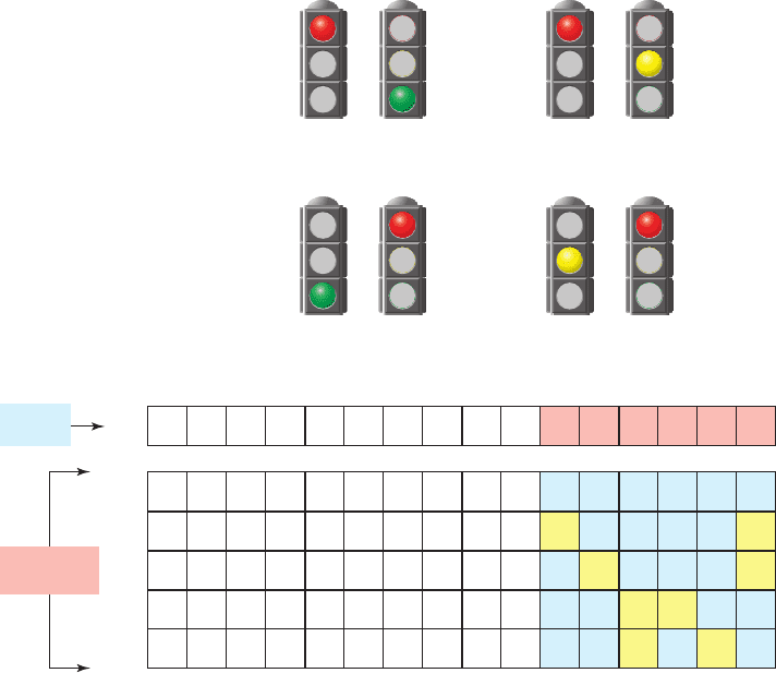
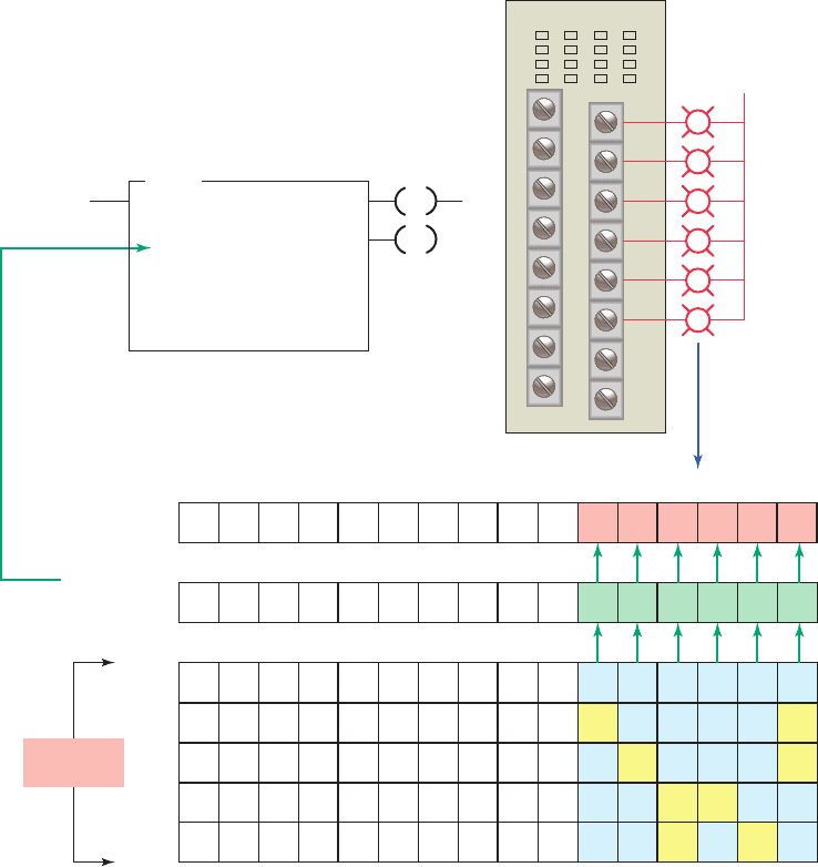
To illustrate the purpose and function of the sequencer
le we will examine the operation of the four-step se-
quence process shown in Figure12-8 . This sequencer is to
be used to control traf c in two directions. The operation
of the process can be summarized as follows:
• Six outputs are to be energized from one 16-point
output module.
• Each light is controlled by one bit address of output
word O:2.
• The rst 6 bits are programmed to execute the fol-
lowing sequence of light outputs:
- Step 1: Outputs O:2.0 (red) and O:2.5 (green)
lights will be energized.
- Step 2: Outputs O:2.0 (red) and O:2.4 (yellow)
will be energized.
- Step 3: Outputs O:2.2 (green) and O:2.3 (red)
will be energized.
- Step 4: Outputs O:2.1 (yellow) and O:2.3 (red)
will be energized.
Figure 12-8 Four-step sequencer.
Start
Positions
Step 1
Step 2
Step 3
Step 4
O:2
B3:0
B3:1
B3:2
B3:3
B3:4
Output
word
Sequencer
file
0
1
1
0
0
0
0
0
0
0
0
0
0
0
0
0
0
0
0
0
0
0
0
0
0
0
0
0
0
0
0
0
0
0
0
0
0
0
0
0
0
0
0
0
0
0
1
0
0
0
0
0
1
0
0
0
0
0
1
1
0
0
0
1
0
0
0
0
0
1
0000000000000000
015141312111098765432
0
0
0
0
0
0
0
0
0
0
1
N/S
O:2.0
O:2.1
O:2.2
O:2.3
O:2.4
O:2.5
E/W
Step 1
N/S E/W
Step 2
N/S E/W
Step 3
N/S E/W
Step 4
pet10882_ch12_242-267.indd 246pet10882_ch12_242-267.indd 246 7/27/10 4:32 PM7/27/10 4:32 PM
Sequencer and Shift Register Instructions Chapter 12 247
• Words B3:0, B3:1, B3:2, B3:3 and B3:4 make up
the sequencer le.
• Binary information (1s and 0s) that re ects the de-
sired on or off light status for each of the four steps
is entered into each word of the sequencer le.
• Before starting the sequence, you need a starting
point where the sequencer is in a neutral position.
This is provided by the start position which is all
zeros.
Due to the way in which the sequencer instruction op-
erates, all output points must be on a single output mod-
ule. When a sequencer operates on an entire output word,
there may be outputs associated with the word that do not
need to be controlled by the sequencer. In our example,
bits 6 through 15 of output word O:2 are not used by the
sequencer but could be used elsewhere in the program. To
prevent the sequencer from controlling these bits of the
output word, a mask word is used. The use of a mask word
is illustrated in Figure12-9 . The operation of the mask
can be summarized as follows:
• The mask word selectively screens out data from the
sequencer word le to the output word.
• The hex number 003Fh is entered as the mask
parameter.
• For each bit of output word O:2 that the sequencer
is to control, the corresponding bit of the mask word
must be set to 1.
• The arrows in the gure indicate the unmasked bits
that are passed through the mask and into the desig-
nation address.
• The dashes in the bits of the designation address
indicate that those bits remain unchanged in the des-
ignation location during the sequencing.
• These unchanged bits therefore can be used inde-
pendently of the sequencer.
Figure 12-9 Sequencer moving data through a mask word.
1000000000011111
Mask
003Fh (hexadecimal)
11111B (binary)
Start
Step 1
Step 2
Step 3
Step 4
B3:0
B3:1
B3:2
B3:3
B3:4
Sequencer
file
0
1
1
0
0
0
0
0
0
0
0
0
0
0
0
0
0
0
0
0
0
0
0
0
0
0
0
0
0
0
0
0
0
0
0
0
0
0
0
0
0
0
0
0
0
0
1
0
0
0
0
0
1
0
0
0
0
0
1
1
0
0
0
1
0
0
0
0
0
1
0
0
0
0
0
0
0
0
0
0
O:2 Destination 0––––––––––00000
015 14 13
EN
DN
121110987654321
SQO
SEQUENCER OUTPUT
File #B3:0
Mask 003Fh
Dest O:2
Control R6:0
Length 4
Position 1
Output module
0
L2
1
2
3
4
5
pet10882_ch12_242-267.indd 247pet10882_ch12_242-267.indd 247 7/27/10 4:32 PM7/27/10 4:32 PM
248 Chapter 12 Sequencer and Shift Register Instructions
The sequencer output instruction requires preceding
logic on the rung where it is located. When this logic goes
from false to true, it triggers the sequencer to perform its
functions. Only when the logic preceding the sequencer
instruction makes the transition from false to true will it
go through its functions of reading the data le, applying
the mask, and transferring the masked data le to the out-
put destination. After this cycle, it waits for another false-
to-true occurrence of the preceding logic to increment to
the next step.
Figure12-10 illustrates how the sequencer moves data
from a le to an output. The operation of the logic rung
can be summarized as follows:
• Pushbutton PB is used to send false-to-true trigger
signals to the sequencer output instruction.
• The position of the sequencer instruction is incre-
mented by one for each false-to-true transition of
the sequencer rung.
• Whenever PB is momentarily closed the sequencer
is both enabled and advanced to the next position.
• When the sequencer is at step 1, the binary informa-
tion in word B3:1 (100001) of the sequencer le is
transferred into word O:2 of the output.
• As a result output O:2/0 and O:2/5 will be on and
all the rest will be off.
• Advancing the sequencer to step 2 will transfer the
data from word B3:2 (010001) into word O:2.
• As a result output O:2/0 and O:2/4 will be on and
all the rest will be off.
• Advancing the sequencer to step 3 will transfer the
data from word B3:3 (001100) into word O:2.
• As a result output O:2/2 and O:2/3 will be on and
all the rest will be off.
• Advancing the sequencer to step 4 will transfer the
data from word B3:4 (001010) into word O:2.
• As a result output O:2/1 and O:2/3 will be on and
all the rest will be off.
• When the position parameter reaches 4 (the value
in the length parameter) all words would have been
moved so the DN (done bit) in the instruction is
setto1.
• On the next false-to-true transition of the rung, with
done bit set, the position pointer is automatically
resetto 1.
Sequencer instructions are usually retentive, and there
can be an upper limit to the number of external outputs
and steps that can be operated on by a single instruction.
Many sequencer instructions reset the sequencer automat-
ically to step 1 on completion of the last sequence step.
Other instructions provide an individual reset control line
or a combination of both.
12.3 Sequencer Programs
A sequencer program can be event-driven or time-driven.
An event-driven sequencer operates similarly to a me-
chanical stepper switch that increments by one step for
each pulse applied to it. A time-driven sequencer operates
similarly to a mechanical drum switch that increments au-
tomatically after a preset time period.
A sequencer chart, such as the one shown in Fig-
ure12-11 , is a table that lists the sequence of operation
of the outputs controlled by the sequencer instruction.
These tables use a matrix-style chart format. A matrix
is a two-dimensional, rectangular array of quantities. A
time-driven sequencer chart usually indicates outputs
on its horizontal axis and the time duration on its verti-
cal axis. An event-driven sequencer indicates outputs
on its horizontal axis and the input, or event, on its ver-
tical axis.
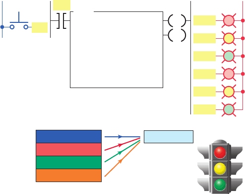
An example of a time-driven sequencer with timed
steps that are not all the same is shown in Figure12-12 .
This sequencer program is used for automatic traf c light
control at a four-way intersection. Output lights operate
in a sequential fashion with variably timed steps. The
system requires two SQO instructions: one for the light
outputs and the other for the timed steps. Both SQOs have
R6:0 for the control and 4 for the length. The rst position
is on for 25 seconds, the second for 5 seconds, the third
for 25seconds, and the fourth for 5 seconds.
Figure 12-10 Sequencer moving data from a fi le to an
output.
Ladder logic program
L1
Input
PB1
PB1
SEQUENCER OUTPUT
File
Mask
Dest
Control
Length
Position
#B3:0
001Fh
O:2
R6:0
4
1
SQO
EN
DN
L2
Output
O:2.5
O:2File #B3:0
O:2.0
O:2.1
O:2.2
O:2.3
O:2.4
1
2
Positions
3
4
100001
010001
001100
001010
Destination
pet10882_ch12_242-267.indd 248pet10882_ch12_242-267.indd 248 7/27/10 4:32 PM7/27/10 4:32 PM
Sequencer and Shift Register Instructions Chapter 12 249
The operation of the time-driven sequencer program
can be summarized as follows:
• The bits controlling the traf c light outputs are
stored in integer le #N7:0 of the rst SQO instruc-
tion. The settings for the output bits for each posi-
tion are entered and stored in binary table format as
shown in Figure12-13 . Each word of the #N7:0 le
is moved from the le by the program to the desti-
nation output word O:2 as previously described.
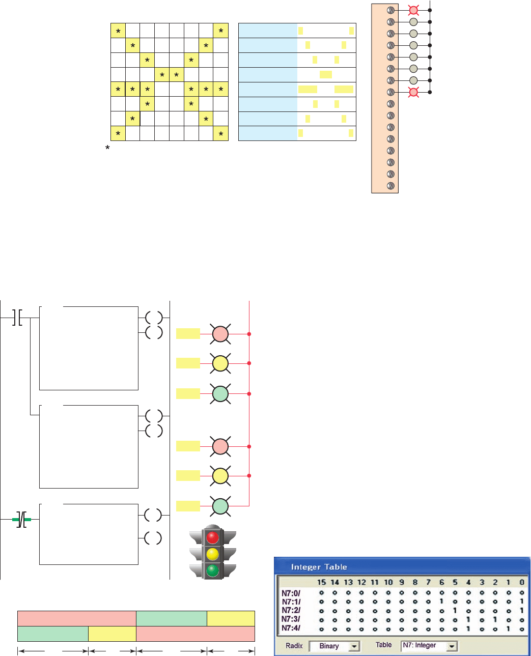
• The second SQO instruction sequencer le, #N7:10,
contains the stored preset timer values 25, 5, 25,
5seconds. These settings are stored in words N7:11,
N7:12, N7:13, and N7:15 as illustrated in Fig-
ure12-14 . Each word of the #N7:10 le is moved
by the program to the destination address T4:1.PRE,
which is the preset value for the timer. The program
moves information from this le to timer T4:1’s
preset. The mask allows the proper data to pass and
blocks the unnecessary data.
• The timer cycles the two SQO instructions through
their four states.
Figure 12-11 Sequencer chart.
Matrix-style chart
0
1
2
3
4
5
6
7
8
9
10
11
12
13
14
15
L2
Output module
at position 1
0
0
0
0
0
0
0
0
0
0
0
0
0
0
0
0
0
0
0
0
0
0
0
0
0
0
0
0
0
0
0
0
0
0
0
0
0
0
0
0
0
0
0
0
0
0
0
0
0
0
0
0
0
0
0
0
0
0
0
0
0
0
0
0
1
0
0
0
1
0
0
1
0
1
0
0
1
0
1
0
0
0
1
0
1
1
0
0
0
0
0
1
0
0
0
0
0
0
0
1
0
0
0
0
0
0
1
0
1
1
0
0
0
1
0
0
1
0
1
0
1
0
0
0
1
0
0
1
Position
Outputs
Sequencer output file words
Indicates that output is energized
1
2
3
4
5
6
7
8
12345670
Figure 12-12 Time-driven sequencer output program.
Timing chart
N/S
E/W
Red
Red
Green Yellow
Yellow
Green
25 s 25 s 5 s5 s
Ladder logic program Outputs
TON
TIMER ON DELAY
Timer
Time base
Preset
Accumulated
T4:1
1.0
25
0
EN
DN
O:2/5
O:2/6
T4:1/DN
SQO
SEQUENCER OUTPUT
File
Mask
Dest
Control
Length
Position
#N7:0
00FFh
O:2
R6:0
4
0
North/South
East/West
EN
DN
L2
SQO
SEQUENCER OUTPUT
File
Mask
Dest
Control
Length
Position
#N7:10
00FFh
T4:1.PRE
R6:0
4
0
EN
DN
O:2/1
O:2/2
O:2/4
T4:1/DN
O:2/0
Figure 12-13 Sequencer fi le #N7:0 light cycle settings.
pet10882_ch12_242-267.indd 249pet10882_ch12_242-267.indd 249 7/27/10 4:32 PM7/27/10 4:32 PM
250 Chapter 12 Sequencer and Shift Register Instructions
• Since both of the SQO instructions have R6:0 for
control and 4 for length they are stepped in unison
to provide a sequentially timed output.
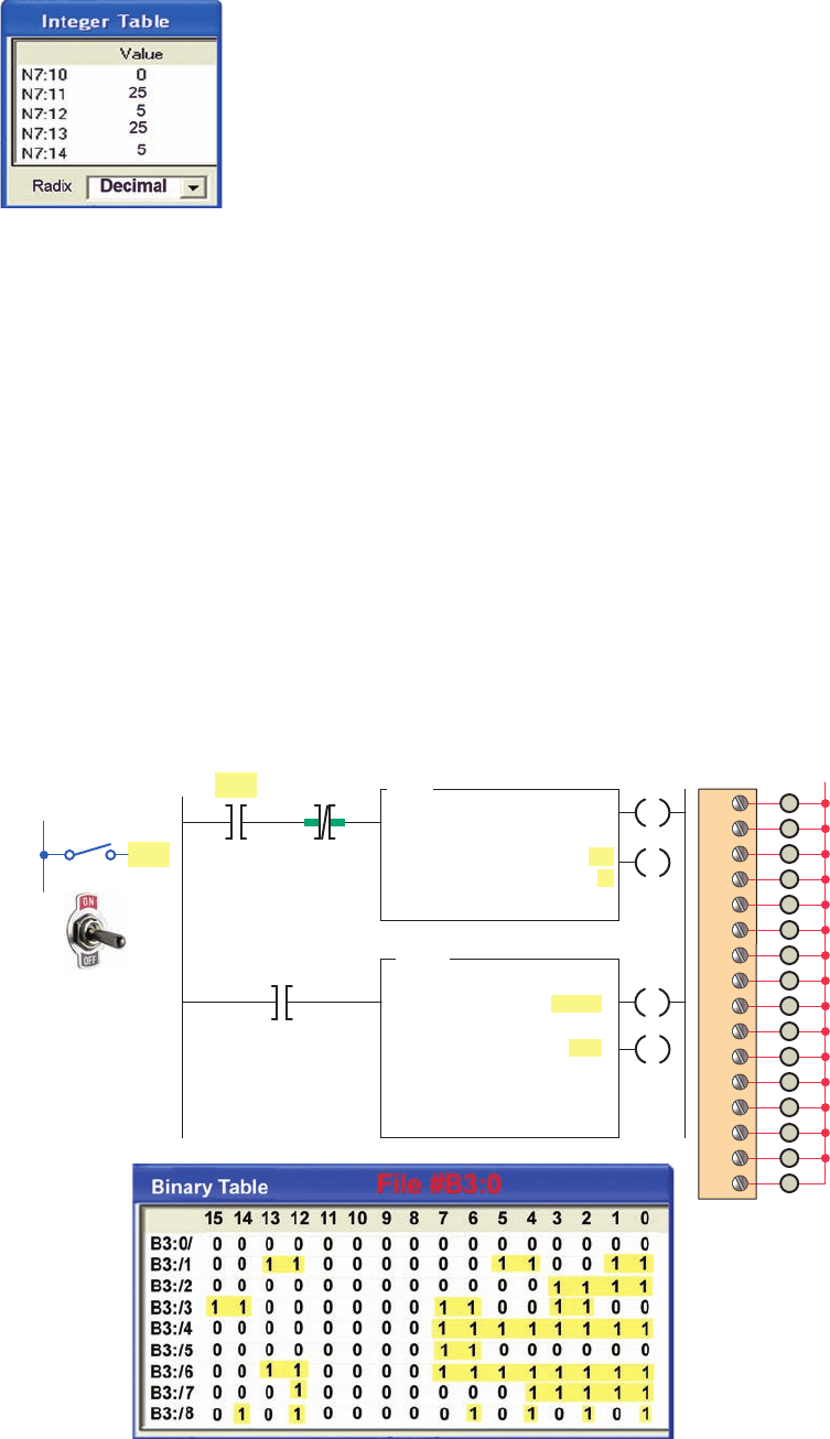
An example of a time-driven sequencer program in
which the time interval between sequencer steps is always
a constant set value is shown in Figure12-15 . The opera-
tion of the program can be summarized as follows:
• The preset time of timer T4:0 is set for 3 seconds.
• The settings of the output bits for each sequencer
position are entered and stored in bit le #B3:0.
• The timer is started by the closing switch SW and
3seconds later the timer done bit is set to1.
• As a result the timer done bit increments the SQO
instruction to the next position and resets the timer.
• The destination is O:2 and all 16 bits of this word
are used for outputs.
• The mask is FFFF hexadecimal or
1111111111111111 binary, which allows all 16 bits
to pass through.
• As long as input SW is closed the program continues
operating with 3 seconds between sequencer steps.
With an event-driven sequencer, the SQO instruction
advances to the next step by an external pulsed input event
rather than a preset time. An example of an event-driven
sequencer is shown in Figure12-16 . The operation of the
program can be summarized as follows:
• The sequencer SQO instruction uses two OR con-
gured sensor switches (S1 and S2).
• Any one of the two parallel paths can make the
SQO rung true.
• As each event occurs, that OR branch makes a false-
to-true transition advancing the sequencer position.
• Data are copied from le #B3:0 at the bit lo-
cations through mask word, F0FF hex or
1111000011111111 binary, to the destination O:2.
Mask bits are set to 1 to pass data and reset to 0 to
mask data.
Figure 12-14 Sequencer fi le #N7:10 timer settings.
Figure 12-15 Time-driven sequencer with constant time interval between steps.
SW
SQO
SEQUENCER OUTPUT
File
Mask
Dest
Control
Length
Position
T4:0/DN
#B3:0
FFFFH
O:2
R6:0
8
0
EN
DN
SW
L2
0
1
2
3
4
5
6
7
8
9
10
11
12
13
14
15
Input
L1
Ladder logic program
TON
TIMER ON DELAY
Timer
Time base
Preset
Accumulated
T4:1
1.0
3
0
EN
O:2
DN
T4:0/DN
pet10882_ch12_242-267.indd 250pet10882_ch12_242-267.indd 250 7/27/10 4:32 PM7/27/10 4:32 PM
Sequencer and Shift Register Instructions Chapter 12 251
• Once the position reaches the last position on the
true-to-false transition of the instruction the position
will reset to 1.
• Note that the data in O:2 match the data in position2
in the le, except for the data in bits 8 through 11.
• Bits 8 through 11 may be controlled from else-
where in the program; they are not affected by the
sequencer instruction because of the 0 in these bit
positions in the mask.
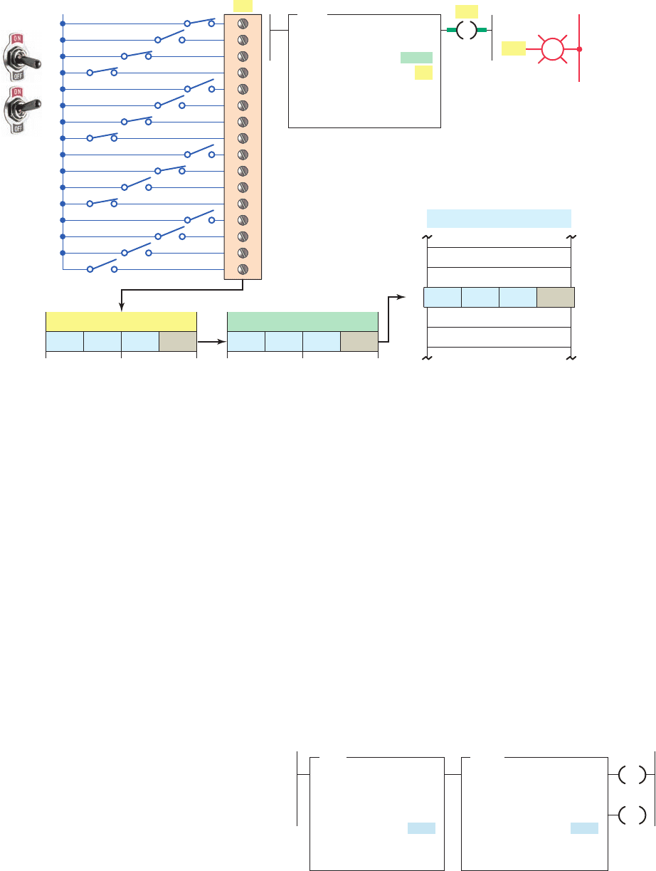
The sequencer input (SQI) instruction allows input
data to be compared for equality against data stored in the
sequencer le. For example, it can make comparisons be-
tween the states of input devices and their desired states:
if the conditions match, the instruction is true.
The SQI instruction is an input instruction available
in Allen-Bradley PLC-5 and ControlLogix controllers.
An example of a PLC sequencer input instruction is
shown in Figure 12-17 . The entries in the instruction
are similar to those in the sequencer output instruction,
except that the destination is replaced by the source.
The operation of the program can be summarized as
follows:
• The SQI instruction compares the input data in
I:3 through the mask FFF0 with the data in the se-
quencer le N7:11 through N7:15 for equality.
• The speci c data in the sequencer le used in the
comparison is identi ed by the position parameter.
• When the unmasked source bits match those of the
corresponding sequencer le word, the instruction
goes true; otherwise, the instruction is false.
• In this example, the data at position 2 match the
unmasked input data, so the SQI instruction is true,
thus making the rung and output PL1 true.
• The input data can indicate the state of an input
device, such as the combination of input switches
shown in this example program.
• Anytime the combination of opened and closed
switches is equal to the combination of 1s and 0s on
a step in the sequencer reference le, the PL1 output
of the sequencer becomes energized.
Figure 12-16 Event-driven sequencer output program.
EN
DN
SQO
SEQUENCER OUTPUT
File
Mask
Dest
Control
Length
Position
Ladder logic program
0
1
2
3
4
5
6
7
8
Output
015 1110 9 8
O:2
Mask
File
Pos
#B3:0
Destination
Pos 2
Current step
0
0
0
1
0
0
0
0
0
0
0
0
1
0
0
0
0
1
0
1
0
0
0
0
1
0
0
0
1
0
0
0
0
1
1
1
0
0
0
0
0
0
0
0
0
0
0
0
0
0
0
0
0
0
0
0
0
0
0
0
0
0
0
0
0
0
0
0
0
0
0
0
0
0
0
1
1
1
1
0
0
0
0
0
1
1
1
1
0
1
0
1
0
0
1
0
1
0
0
0
1
0
0
1
0
1
1
1
0
0
1
1
1
0
1
1
0
0
0
1
1
1
0
1
1
1
0
1
1
0
1
0
1
1
0
0
1
1
0
1
0
1
1
1
0000 00001111
#B3:0
F0FF
O:2
R6:0
8
2
Pos
0
1
2
3
4
5
6
7
8
9
10
11
12
13
14
15
L2
Module O:2
1111000011111111
Inputs
L1
S1
S2
S2
S1
Field triggered input events
S1
S2
pet10882_ch12_242-267.indd 251pet10882_ch12_242-267.indd 251 7/27/10 4:33 PM7/27/10 4:33 PM
252 Chapter 12 Sequencer and Shift Register Instructions
The SQI instruction uses a control register like the
SQO instruction but does not have a done bit. In addition,
the SQI instruction does not automatically increment its
position each time its control logic makes a false-to-true
transition at its input. If the SQI instruction is used alone,
the position value must be changed by another instruc-
tion (such as the move instruction) to select a new input
le value to compare against the value from the source
address.
When the SQI is paired with an SQO instruction
with identical control addresses the position is incre-
mented by the SQO instruction for both. The program of
Figure12-18 illustrates the use of the sequencer input and
sequencer output instructions in pairs to monitor and con-
trol, respectively, a sequential operation. The operation of
the program can be summarized as follows:
• The same control address, length value, and position
value is used for each instruction.
• The sequencer input instruction is indexed by the
sequencer output instruction because both control
elements have the same address, R6:5.
• This type of programming technique allows input
and output sequences to function in unison, causing
a speci c output sequence to occur when a speci c
input sequence takes place.
The Allen-Bradley SLC 500’s sequencer compare
(SQC) instructions are similar but not identical to the SQI
instruction. Differences between the two include:
• The SQC instruction is an output rather than an
input instruction.
• The SQC instruction increments the position
parameter
• The SQC instruction has an additional status
bit — the found bit (FD). When the source
patternmatches the sequencer le word the
FDissetto1. It is zero under all other
conditions.
Figure 12-17 Sequencer input (SQI) instruction.
L1
Input module
Ι:3
Inputs
SQΙ
SEQUENCER INPUT
File
Mask
Source
Control
Length
Position
#N7:11
FFF0
Ι:3
R6:21
4
2
Ladder logic program
PL1
00 00
Input word Ι:3
10 10 11 00 11 01 11 11 11 11 11 11 00 00
00 00 10 10 11 00 11 01
0
Step
1
3
2
4
#N7:11
Word
Sequencer file
12
14
13
15
Output
L2
PL1
Mask value
Figure 12-18 Sequencer input and sequencer output
instructions used in pairs.
SQO
SEQUENCER OUTPUT
File
Mask
Dest
Control
Length
Position
#N7:20
00FF
O:2
R6:5
8
0
SQI
SEQUENCER INPUT
File
Mask
Source
Control
Length
Position
#N7:1
00FF
I:3
R6:5
8
0
EN
DN
Ladder logic program
pet10882_ch12_242-267.indd 252pet10882_ch12_242-267.indd 252 7/27/10 4:33 PM7/27/10 4:33 PM