Petruzella F.D. Programmable Logic Controllers
Подождите немного. Документ загружается.

PLC Installation Practices, Editing, and Troubleshooting Chapter 13 273
Ground loops can cause problems by adding or sub-
tracting current or voltage from input signal devices.
A ground loop circuit can develop when each device’s
ground is tied to a different earth potential thereby allow-
ing current to ow between the grounds, as illustrated in
Figure 13-10 . If a varying magnetic eld passes through
one of these ground loops, a voltage is produced and cur-
rent ows in the loop. The receiving device is unable to
differentiate between the wanted and unwanted signals
and, thus, can’t accurately re ect actual process condi-
tions. Certain connections require shielded cables to help
reduce the effects of electrical noise coupling. Each shield
should be grounded at one end only, as a shield grounded
at both ends forms a ground loop.
of conductors, color codes, and connections neces-
sary for safe grounding of electrical components. In
addition, most manufacturers provide detailed infor-
mation on the proper grounding methods to use in an
enclosure.
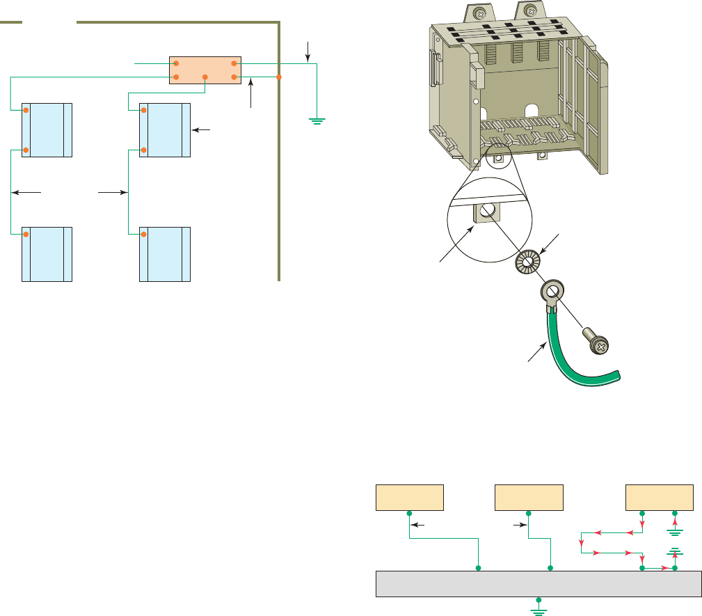
Figure 13-8 illustrates a PLC grounding system. A
properly installed grounding system will provide a low-
impedance path to earth ground. The complete PLC in-
stallation, including enclosures, CPU and I/O chassis,
and power supplies are all connected to a single low-
impedance ground. These connections should exhibit low
DC resistance and low high-frequency impedance. A cen-
tral ground bus bar is provided as a single point of refer-
ence inside the enclosure to which all chassis and power
supply equipment grounding conductors are connected.
The ground bus is then connected to the building’s earth
ground.
In the event of a high value of ground current, the
temperature of the conductor could cause the solder to
melt, resulting in interruption of the ground connec-
tion. Therefore the grounding path must be permanent
(no solder), continuous, and able to conduct safely the
ground-fault current in the system with minimal imped-
ance. Paint or other nonconductive material should be
scraped away from the area where a chassis makes con-
tact with the enclosure. The minimum ground wire size
should be No. 12 AWG stranded copper for PLC equip-
ment grounds and No. 8 AWG stranded copper for en-
closure backplane grounds. Ground connections should
be made with a star washer between the grounding wire
and lug and metal enclosure surface, as illustrated in
Figure 13-9 .
Figure 13-8 PLC grounding system.
CPU
or I/O
rack
CPU
or I/O
rack
Equipment
grounding
conductor
Equipment
grounding
conductor
Ground bus
Ground for slot
power supply
To grounding
electrode
system
Grounding
electrode
system
CPU
or I/O
rack
CPU
or I/O
rack
Enclosure
Figure 13-9 Make ground connections using a star
washer.
Star washer
To ground bus
Chassis
mounting tab
Equipment grounding
conductor (ground lug
with (8 AWG) wire)
Figure 13-10 Formation of ground loops.
Source
No ground loops
Source
Ground bus
Source
Ground
loop
formed
pet10882_ch13_268-290.indd 273pet10882_ch13_268-290.indd 273 7/27/10 6:03 PM7/27/10 6:03 PM
274 Chapter 13 PLC Installation Practices, Editing, and Troubleshooting
loads. The operation of the circuit can be summarized
as follows:
• The diode is connected in reverse-bias across the
solenoid load.
• In normal operation, the electric current can’t
ow through the diode, so it ows through the
solenoid coil.
• When voltage to the solenoid is switched off a
voltage opposite in polarity to the original applied
voltage is generated by the collapsing magnetic
eld.
• The induced voltage creates a current ow
through the diode bleeding off the high
voltage spike.
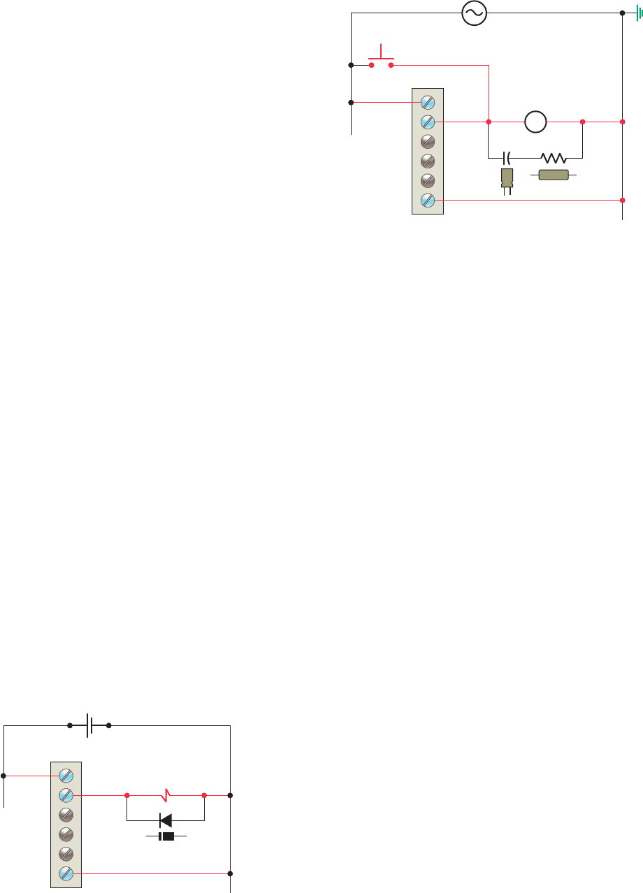
Figure 13-12 illustrates how an RC (resistor/capacitor)
snubber circuit is connected for suppressing AC load de-
vices. The operation of the circuit can be summarized as
follows:
• The voltage peak, which occurs at the instant the
current path to the coil is opened, is safely short-
circuited by the RC network.
• The resistor and capacitor connected in series slows
the rate of rise of the transient voltage.
• The voltage across the capacitor cannot change
instantaneously, so a decreasing transient current
will ow through it for a small fraction of a second,
allowing the voltage to increase more slowly when
the circuit is opened.
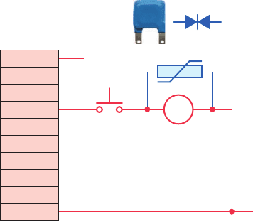
The metal oxide varistor (MOV) surge suppressor,
shown in Figure 13-13 , is the most popular surge protec-
tion device. It functions in a manner similar to two zener
13.5 Voltage Variations and Surges
The power supply section of the PLC system is built to
sustain line uctuations and still allow the system to func-
tion within its operating range. If voltage uctuations ex-
ceed this range, then a system shutdown will occur. In
areas where excessive line voltage variation or extended
brownouts are anticipated, installing a constant voltage
(CV) transformer may be required to minimize nuisance
shutdowns of the PLC.
Isolation transformers are used in some PLC systems
to isolate the PLC from electrical disturbances generated
by other equipment connected to the distribution system.
Although the PLC is designed to operate in harsh envi-
ronments, other equipment may generate considerable
amounts of interference that may result in intermittent
disturbances in normal operation. A normal practice is
to place the PLC power supply and I/O devices on a
separate transformer that may also serve as a step-down
transformer to reduce the incoming voltage to the de-
sired level.
When current in an inductive load is interrupted or turned
off, a very high voltage spike is generated. This high volt-
age can be reduced or eliminated through suppression
techniques which absorb the inductive induced voltage.
Generally, output modules designed to drive inductive loads
include suppression networks built in as part of the module
circuit.
An additional external suppression device is recom-
mended if an output module is used to control devices
such as relays, solenoids, motor starters, or motors. The
suppression device is wired in parallel (directly across)
and as close as possible to the load device. The sup-
pression components must be rated appropriately to
suppress the switching transient characteristic of the
particular inductive device. Figure 13-11 illustrates
how a diode is connected to suppress DC inductive
Figure 13-11 Diode connected to suppress DC inductive
loads.
()
L1() L2()
Reversed-bias
diode
Solenoid coil
Output module
Figure 13-12 RC snubber circuit connected to suppress
AC loads.
Output
module
CR
L2
L1
PB
M
L1
L2
pet10882_ch13_268-290.indd 274pet10882_ch13_268-290.indd 274 7/27/10 6:03 PM7/27/10 6:03 PM
PLC Installation Practices, Editing, and Troubleshooting Chapter 13 275
PLC, the ladder logic program, the I/O devices, and all
associated wiring operate according to speci cations. Be-
fore commissioning any control system, you should have
a good understanding of how the control system operates
and how the various components interact. The following
are general steps to be followed when commissioning a
PLC system:
• Before applying power to the PLC or the input
devices, disconnect or otherwise isolate any output
device that could potentially cause damage or injury.
Typically this precaution would pertain to outputs that
cause movement such as starting a motor or operating
a valve.
• Apply power to the PLC and input devices. Mea-
sure the voltage to verify that rated voltage is being
applied.
• Examine the PLC’s status indicator lights. If power
is properly applied, the power indicator should be
on, and there should be no fault indication. If the
PLC does not power up properly, it may be faulty.
PLCs rarely fail, but if they do fail, it usually hap-
pens immediately upon powering up.
• Verify that you have communication with the PLC
via the programming device that is running the PLC
programming software.
• Place the PLC in a mode that prevents it from ener-
gizing its output circuits. Depending on the make of
the PLC, this mode may be called disable, continu-
ous test, or single-scan mode. This mode will allow
you to monitor input devices, execute the program,
and update the output image le while keeping the
output circuits de-energized.
• Manually activate each input device, one at a
time, to verify that the PLC’s input status lights
turn on and off as expected. Monitor the associ-
ated condition instruction to verify that the input
device corresponds to the correct program address
and that the instruction turns true or false as
expected.
• Manually test each output. One way you can do this
is by applying power to the terminal where the out-
put device is wired. This test will check the output
eld device and its associated wiring.
• After verifying all inputs, outputs, and program ad-
dresses, verify all preset values for counters, timers,
and so on.
• Reconnect any output devices that may have been
disconnected and place the PLC in the run mode.
Test the operation of all emergency stop buttons and
the total system operation.
diodes connected back-to-back. The operation of a MOV
can be summarized as follows:
• The device acts as an open circuit until the volt-
ageacross it in either direction exceeds its rated
value.
• Any greater voltage peak instantly makes the device
act like a short circuit that bypasses this voltage
away from the rest of the circuit.
13.6 Program Editing
andCommissioning
After you have entered the rungs for your program, you
may need to modify them. Editing is simply the ability to
make changes to an existing program through a variety of
editing functions. Using the editing function, instructions
and rungs can be added or deleted; addresses, data, and
bits can be changed. Again, the editing format varies with
different manufacturers and PLC models.
Today, most PLC programming software is Microsoft
Windows based, so if you are familiar with Windows and
know how to point and click with a mouse, you should
have no problem editing a program. In general, both in-
structions and rungs are selected simply by clicking on
them with the left mouse button. Double clicking with the
left mouse button allows you to edit an instruction’s ad-
dress, whereas right clicking displays a pop-up menu of
related editing commands. If you want to include addi-
tional explanation of a symbol or address, you can place
an address description on your ladder rung directly above
the symbol. To add a page or rung comment, right click
on the rung number to which you wish to add the page or
rung comment.
Preparing a control process for start-up, also called
commissioning, involves a series of tests to ensure that the
AC or DC
output module
VAC/VDC
OUT 0
OUT 1
OUT 2
OUT 3
OUT 4
OUT 5
OUT 6
OUT 7
COM
Inductive load
DC Com or L2
MOV
DC or L1
Figure 13-13 Metal oxide varistor (MOV) surge
suppressor.
pet10882_ch13_268-290.indd 275pet10882_ch13_268-290.indd 275 7/27/10 6:03 PM7/27/10 6:03 PM
276 Chapter 13 PLC Installation Practices, Editing, and Troubleshooting
13.7 Programming and Monitoring
When you program a PLC, several instruction entry
modes are available, depending on the manufacturer and
the model of the unit. A personal computer, with appro-
priate software, is generally used to program and monitor
the program in the PLC. Additionally, it makes possible
of ine programming, which involves writing and storing
the program in the personal computer without its being
connected to the PLC and later downloading it to the
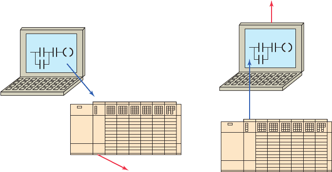
PLC. Figure 13-14 illustrates how programs are down-
loaded and uploaded from and to the computer.
With online programming the program can be modi-
ed, the modi cations can be tested, and nally they can
be accepted or rejected while the PLC is running. How-
ever, of ine programming is the safest manner in which to
edit a program because additions, changes, and deletions
do not affect the operation of the system until downloaded
to the PLC.
Many manufacturers provide a continuous test mode
that causes the processor to operate from the user pro-
gram without energizing any outputs. This mode allows
the control program to be executed and debugged while
the outputs are disabled. A check of each rung can be
done by monitoring the corresponding output rung on the
programming device. A single-scan test mode may also
be available for debugging the control logic. This mode
causes the processor to complete a single scan of the user
program each time the single-scan key is pressed with no
outputs being energized.
An online programming mode permits the user to
change the program during machine operation. As the
PLC controls its equipment or process, the user can add,
change, or delete control instructions and data values as
desired. Any modi cation made is executed immediately
on entry of the instruction. Therefore, the user should
assess in advance all possible sequences of machine
operation that will result from the change. Online pro-
gramming should be done only by experienced person-
nel who understand fully the operation of the PLC they
are dealing with and the machinery being controlled. If
at all possible, changes should be made of ine to pro-
vide a safe transition from existing programming to new
programming.
Two useful monitoring tools provided with PLC pro-
gramming packages are data monitor and cross reference.
Data monitoring functions allow you to monitor and/or
modify speci ed program variables. The cross reference
function allows you to search each instance of a particular
address.
The data monitor feature allows you to display data
from any place in the data table. Depending on the
PLC, the data monitor function can be used to do the
following:
• View data within an instruction
• Store data or values for an instruction prior to use
• Set or reset values and/or bits during a debug opera-
tion for control purposes
• Change the radix or data format
Figure 13-14 Downloading and uploading PLC program.
(a) Downloading a program (b) Uploading a program
Program from the computer
is loaded into the PLC.
Program that was in the
PLC is lost.
Program from the PLC
is loaded into the computer.
Program that was in the
PLC remains unchanged.
Unsaved program in the
computer is lost.
pet10882_ch13_268-290.indd 276pet10882_ch13_268-290.indd 276 7/27/10 6:03 PM7/27/10 6:03 PM
PLC Installation Practices, Editing, and Troubleshooting Chapter 13 277
The status of the bit(s) (on or off) and the length of time the
bit(s) remained on or off (in hours, minutes, seconds, and
hundredths of a second) are displayed. In a contact histo-
gram le, the accumulated time indicates the total time that
the histogram function was running. The delta time of the
contact histogram indicates the elapsed time between the
changes in states. Contact histograms are extremely useful
Figure 13-15 shows the data le folder and window
for the Allen-Bradley SLC 500 PLC and its associated
RSLogix software. The data le folder allows the user
to determine the status of I/O les as well as the sta-
tus le (S2), binary le (B3), timer le (T4), counter
le (C5), control le (R6), integer le (N7), and the
oating-point le (F8). Always be careful when manip-
ulating data using the data monitor function. Changing
data could affect the program and turn output devices
on or off.
When troubleshooting a PLC, it may be necessary to
locate each instance of a particular address in the ladder
program. The cross reference function searches all pro-
gram les to locate each instance of the selected address.
A user can then trace the operation by nding all the
places where a particular output coil or contact with the
same address is used in the program. Figure 13-16 shows
a sample cross reference report for the Allen-Bradley
SLC 500 PLC and its associated RSLogix software. Its
contents can be summarized as follows:
• The report contains all the addresses used in the
program.
• Addresses are displayed in the same order as the
data table les.
• The address that the search was performed for
(O:2/1) is highlighted.
• The description for each address is displayed.
• Listing includes the instruction type, program le,
and rung number for each address.
• Each occurrence of the address is displayed, starting
with program le 2 and rung 0.
The contact histogram function allows you to view the
transition history (the on and off states) of a data table value.
Figure 13-15 Data fi le folder and window.
Data file folders
Data Files
Cross Reference
O:0-OUTPUT
I:1-INPUT
S2-STATUS
B3-BINARY
T4-TIMER
C5-COUNTER
R6-CONTROL
N7-INTEGER
F8-FLOAT
Data file window
Input Table
15
0
0
14
0
0
11
0
0
10
0
0
9
0
0
6
0
0
5
0
0
3
0
0
13
0
0
8
0
0
7
0
0
4
0
1
2
0
0
1
0
0
12
0
0
0
0
0
I:1.0
I:2.0
Radix:
Binary
Table:
Address
O:0:Output
I:1:Input
S2: Status
B3: Binary
T4: Timer
C5: Counter
R6: Control
N7: Integer
F8: Float
Figure 13-16 Sample cross reference report.
Stop PB
I:1/1
Start PB
Motor control relay
I:1/2
O:2/1
O:2/1
Motor control relay
O:2/1
Motor control relay
O:2/3
Run pilot light
Cross Reference Report - Sorted by Address
0:2/1 – Motor Control Realy
0:2/3 – Run Pilot Light
I
:1/1 – Stop PB
I:1/2 – Start PB
OTE – File #2 MAIN_PROG – 0
OTE – File #2 MAIN_PROG – 1
XIC – File #2 MAIN_PROG – 0, 1
XIC – File #2 MAIN_PROG – 0
XIC – File #2 MAIN_PROG – 0
Sort By Symbol Refresh Help
1
0
pet10882_ch13_268-290.indd 277pet10882_ch13_268-290.indd 277 7/27/10 6:03 PM7/27/10 6:03 PM
278 Chapter 13 PLC Installation Practices, Editing, and Troubleshooting
for detecting intermittent problems, either hardware- or
logic-related. By tracking the status and time between sta-
tus changes, you can detect different types of problems.
13.8 Preventive Maintenance
The biggest deterrent to PLC system faults is a proper pre-
ventive maintenance program. Although PLCs have been
designed to minimize maintenance and provide trouble-
free operation, there are several preventive measures that
should be looked at regularly.
Many control systems operate processes that must be
shut down for short periods for product changes. The fol-
lowing preventive maintenance tasks should be carried
out during these short shutdown periods:
• Any lters that have been installed in enclosures
should be cleaned or replaced to ensure that clear
air circulation is present inside the enclosure.
• Dust or dirt accumulated on PLC circuit boards
should be cleaned. If dust is allowed to build up on
heat sinks and electronic circuitry, an obstruction of
heat dissipation could occur and cause circuit mal-
function. Furthermore, if conductive dust reaches
the electronic boards, a short circuit could result
and cause permanent damage to the circuit board.
Ensuring that the enclosure door is kept closed will
prevent the rapid buildup of these contaminants.
• Connections to the I/O modules should be checked
for tightness to ensure that all plugs, sockets, termi-
nal strips, and module connections are making con-
nections and that the module is installed securely.
Loose connections may result not only in improper
function of the controller but also in damage to the
components of the system.
• All eld I/O devices should be inspected to en-
sure that they are adjusted properly. Circuit boards
dealing with process control analogs should be
calibrated every 6 months. Other devices, such as
sensors, should be serviced on a monthly basis.
Field devices in the environment, which have to
translate mechanical signals into electrical, may
gum up, get dirty, crack, or break—and then they
will no longer trip at the correct setting.
• Care should be taken to ensure that heavy noise- or
heat-generating equipment is not moved too close to
the PLC.
• Check the condition of the battery that backs up the
RAM memory in the CPU ( Figure 13-17 ). Most
CPUs have a status indicator that shows whether the
battery’s voltage is suf cient to back up the memory
stored in the PLC. If a battery module is to be
replaced, it must be replaced with exactly the same
type of battery module.
• Stock commonly needed spare parts. Input and output
modules are the PLC components that fail most often.
• Keep a master copy of operating programs used.
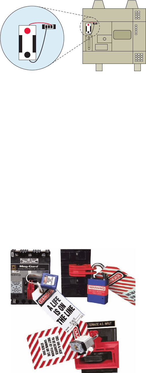
To avoid injury to personnel and to prevent equip-
ment damage, connections should always be checked
with power removed from the system. In addition to dis-
connecting electrical power, all other sources of power
(pneumatic and hydraulic) should be de-energized before
someone works on a machine or process controlled by a
PLC. Most companies use lockout and tagout procedures,
shown in Figure13-18 , to make sure that equipment does
not operate while maintenance and repairs are conducted.
A personnel protection tag is placed on the power source
for the equipment and the PLC, and it can be removed
only by the person who originally placed the tag. In ad-
dition to the tag, a lock is also attached so that equipment
cannot be energized.
Figure 13-17 CPU backup memory battery.
Bat
+
–
Bat
+
–
Figure 13-18 Lockout/tagout devices.
Source: Photo courtesy Panduit Corporation, www.panduit.com.
pet10882_ch13_268-290.indd 278pet10882_ch13_268-290.indd 278 7/27/10 6:03 PM7/27/10 6:03 PM

PLC Installation Practices, Editing, and Troubleshooting Chapter 13 279
13.9 Troubleshooting
In the event of a PLC fault, you should employ a care-
ful and systematic approach to troubleshoot the system to
resolve the problem. PLCs are relatively easy to trouble-
shoot because the control program can be displayed on
a monitor and watched in real time as it executes. If a
control system has been operating, you can be fairly con-
dent of the accuracy of the program logic. For a system
that has never worked or is just being commissioned, pro-
gramming errors should be considered.
When a problem occurs, the rst step in the trouble-
shooting procedure is to identify the problem and its
source. The source of a problem can generally be nar-
rowed down to the processor module, I/O hardware, wir-
ing, machine inputs or outputs, or ladder logic program.
Once a problem is recognized, it is usually quite simple to
deal with. The following sections will deal with trouble-
shooting these potential problem areas.
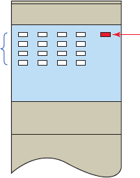
Processor Module
The processor is responsible for the self-detection
of po-
tential problems. It performs error checks during its op-
eration and sends status information to indicators that are
normally located on the front of the processor module.
You can diagnose processor faults or obtain more detailed
information about the processor by accessing the proces-
sor status through programming software. Figure 13-19
shows sample diagnostics LEDs found on a processor
module. What they indicate can be summarized as follows:
RUN (Green)
• On steady indicates that the process is in the RUN
mode.
• Flashing during operation indicates that the process
is transferring a program from RAM to the memory
module.
• Off indicates that processor is in a mode other than
RUN.
FLT (Red)
• Flashing at power-up indicates that the processor
has not been con gured.
• Flashing during operation indicates a major error
either in the processor, chassis, or memory.
• On steady indicates that a fatal error is present (no
communications).
• Off indicates there are no errors.
BATT (Red)
• On steady indicates the battery voltage has fallen
below a threshold level, or the battery is missing or
not connected.
• Off indicates that the battery is functional.
The processor then monitors itself continually for any
problems that might cause the controller to execute the
user program improperly. Depending on the controller, a
set of fault relay contacts may be available. The fault relay
is controlled by the processor and is activated when one or
more speci c fault conditions occur. The fault relay con-
tacts are used to disable the outputs and signal a failure.
Most PLCs incorporate a watchdog timer to moni-
tor the scan process of the system. The watchdog timer
is usually a separate timing circuit that must be set and
reset by the processor within a predetermined period. The
watchdog timer circuit monitors how long it takes the
CPU to complete a scan. If the CPU scan takes too long, a
watchdog major error will be declared. PLC user manuals
will show how to apply this function.
The PLC processor hardware is not likely to fail because
today’s microprocessors and microcomputer hardware are
very reliable when operated within the stated limits of tem-
perature, moisture, and so on. The PLC processor chassis
is typically designed to withstand harsh environments.
Input Malfunctions
If the controller is operating in the RUN mode but output
de
vices do not operate as programmed, the faults could be
associated with any of the following:
• Input and output wiring between eld devices and
modules
• Field device or module power supplies
• Input sensing devices
• Output actuators
• PLC I/O modules
• PLC processor
Narrowing down the problem source can usually be ac-
complished by comparing the actual status of the suspect
I/O with controller status indicators. Usually each input
or output device has at least two status indicators. One of
these indicators is on the I/O module; the other indicator
is provided by the programming device monitor.
Figure 13-19 Processor diagnostics LEDs.
RUN
FLT
BATT
CPU
pet10882_ch13_268-290.indd 279pet10882_ch13_268-290.indd 279 7/27/10 6:03 PM7/27/10 6:03 PM
280 Chapter 13 PLC Installation Practices, Editing, and Troubleshooting
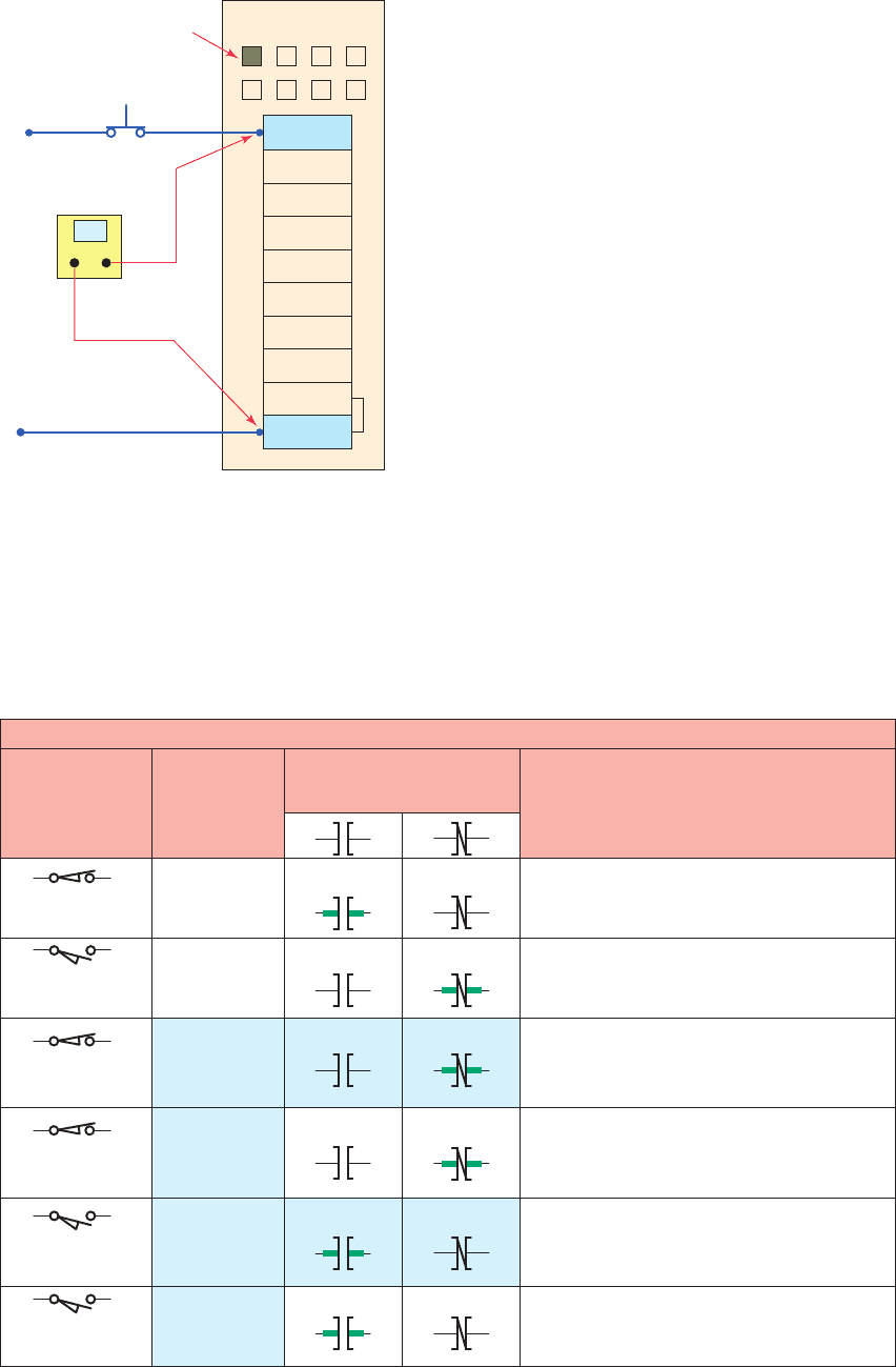
The circuit of Figure 13-20 illustrates how to check for
discrete input malfunctions. The steps taken can be sum-
marized as follows:
• When input hardware is suspected to be the source
of a problem, the rst check is to see if the status
indicator on the input module illuminates when it is
receiving power from its corresponding input device
(e.g., pushbutton, limit switch).
• If the status indicator on the input module does not
illuminate when the input device is on, take a volt-
age measurement across the input terminal to check
for the proper voltage level.
• If the voltage level is correct, then the input module
should be replaced.
• If the voltage level is not correct, power supply, wir-
ing, or input device may be faulty.
If the programming device monitor does not show the
correct status indication for a condition instruction, the
input module may not be converting the input signal prop-
erly to the logic level voltage required by the processor
module. In this case, the input module should be replaced.
If a replacement module does not eliminate the problem
and wiring is assumed to be correct, then the I/O rack,
communication cable, or processor should be suspected.
Figure 13-21 shows a typical input device troubleshooting
guide. This guide reviews condition instructions and how
their true/false status relates to external input devices.
Figure 13-20 Checking for input malfunctions.
IN 1
IN 2
IN 3
IN 4
IN 5
IN 6
IN 7
DC COM
Input module
LED indicator
not illuminated
Input pushbutton
contacts closed
24 V DC
Common
Check input
voltage level
?
IN 0
DC COM
Figure 13-21 Input troubleshooting guide.
Input device troubleshooting guide
None - correct indications
Input module
status indicator
Input
device condition
ON
ON
OFF
ON
OFF
Monitor display
status indicator
Possible
fault(s)
None - correct indications
Input voltage, status indicator, and ladder
instructions agree but not with sensor condition.
Short circuit in the field device or wiring.
Sensor condition, input voltage, status indicator
are correct. Ladder instructions have incorrect
indications. Input module or processor fault.
Status indicator and instructions agree but not
with the sensor condition. Open field device
or wiring.
Sensor condition, input voltage, status indicator
are correct. Ladder instructions have incorrect
indications. Input module or processor fault.
Tr ue
Tr ue
Tr ue
False
False
False
False
False
Tr ue
Tr ue
Tr ue
False
Closed — ON
24 V DC input
Closed — ON
24 V DC input
Closed — ON
0 V DC input
OFF
Open — OFF
0 V DC input
Open — OFF
0 V DC input
Open — OFF
24 V DC input
pet10882_ch13_268-290.indd 280pet10882_ch13_268-290.indd 280 7/27/10 6:03 PM7/27/10 6:03 PM
PLC Installation Practices, Editing, and Troubleshooting Chapter 13 281
Output Malfunctions
In addition to the logic indicator, some output modules
incorporate either a blo
wn fuse indicator or a power indi-
cator or both. A blown fuse indicator indicates the status
of the protective fuse in the output circuit, while a power
indicator shows that power is being applied to the load.
Electronic protection, as shown in Figure 13-22 , is also
used to provide protection for the modules from short-
circuit and overload current conditions. The protection
is based on a thermal cut-out principle. In the event of
a short-circuit or overload current condition on an out-
put channel, that channel will limit current within mil-
liseconds after its thermal cut-out temperature has been
reached. All other channels continue to operate as di-
rected by the processor.
When an output does not energize as expected, rst
check the output module blown fuse indicator. Many out-
put modules have each output fused. This indicator will
normally illuminate only when the output circuit corre-
sponding to the blown fuse is energized. If this indicator
is illuminated, correct the cause of the malfunction and
replace the blown fuse in the module.
Figure 13-23 shows a typical discrete output module
troubleshooting guide. In general, the following items
should be noted when troubleshooting discrete output
modules:
• If the blown fuse indicator is not illuminated (fuse
OK), then check to see if the output device is re-
sponding to the LED status indicator.
• An output module’s logic status indicator func-
tions similarly to an input module’s status indica-
tor. When it is on, the status LED indicates that the
module’s logic circuitry has recognized a command
from the processor to turn on.
• If an output rung is energized, the module status
indicator is on, and the output device is not respond-
ing, then the wiring to the output device or the out-
put device itself should be suspected.
• If, according to the programming device monitor,
an output device is commanded to turn on but the
status indicator is off, then the output module or
processors may be at fault.
• Check voltage at output; if incorrect, power supply,
wiring, or output device may be faulty.
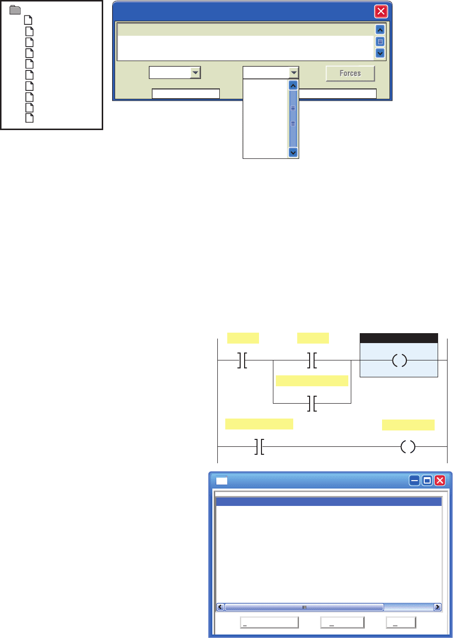
Ladder Logic Program
Many PLC software programs offer various software
checks used to v
erify program logic. Figure 13-24 shows
a sample of verifying program errors using RSLogix 500
software. Selecting edit then verify project will check
the program for errors. The sample shows what the error
message might look like.
The ladder logic program itself is not likely to fail, as-
suming that the program was at one time working cor-
rectly. A hardware fault in the memory IC that holds the
ladder logic program could alter the program, but this is
a PLC hardware failure. If all other possible sources of
trouble have been eliminated, the ladder logic program
should be reloaded into the PLC from the master copy of
the program. Make sure the master copy of the program is
up to date before you download it to the PLC.
Start program troubleshooting by identifying which
outputs operate properly and which outputs do not. Then
trace back from the output on the nonfunctioning rung and
examine the logic to determine what may be preventing
the output from energizing. Common logic errors include:
• Programming an examine if closed instruction
instead of an examine if open (or vice versa)
• Using an incorrect address in the program
Although the ladder logic program is not likely to fail,
the process may be in a state that was unaccounted for in
the original program and thus is not controlled properly.
In this case, the program needs to be modi ed to include
this new state. A careful examination of the description of
the control system and the ladder logic program can help
identify this type of fault.
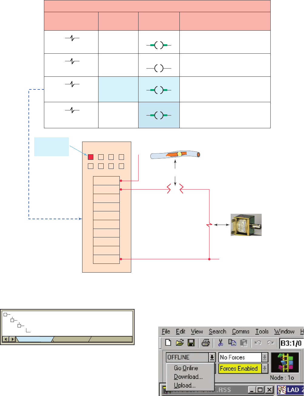
The force on and force off instructions allow you to turn
speci c bits on or off for testing purposes. Figure 13-25
illustrates how forces are identi ed as being enabled or dis-
abled in RSLogix 500 software. Forcing lets you simulate
operation or control an output device. For example, forcing
a solenoid valve on will tell you immediately whether the
solenoid is functional when the program is bypassed. If it
is, the problem must be related to the software and not the
hardware. If the output fails to respond when forced, either
the actual output module is causing the problem or the so-
lenoid itself is malfunctioning. Take all necessary precau-
tions to protect personnel and equipment during forcing.
Figure 13-22 Electronic output module protection.
E
F
U
S
E
Status
indicators
Output
Electronic
protection
LED
pet10882_ch13_268-290.indd 281pet10882_ch13_268-290.indd 281 7/27/10 6:03 PM7/27/10 6:03 PM
282 Chapter 13 PLC Installation Practices, Editing, and Troubleshooting
Certain diagnostic instructions may be included as part
of a PLC’s instruction set for troubleshooting purposes.
The temporary end (TND) instruction, shown in Fig-
ure13-26 , is used when you want to change the amount of
logic scanned to progressively debug your program. The
Output device troubleshooting guide
None - correct indication
Output module
status indicator
Output device
condition
De-energized — OFF
Energized — ON
ON
OFF
ON
OFF
Monitor display
status indicator
Fault(s)
None - correct indication
Output instruction and status indicator
agree but the field device does not.
Open field device or wiring.
Module circuit or fuse.
Field device status and status indicator
agree but the output condition does not.
Module circuit or fuse.
De-energized — OFF
De-energized — OFF
Output module
status indicator
ON
VAC
OUT 0
OUT 1
OUT 2
OUT 3
OUT 4
OUT 5
OUT 6
OUT 7
AC COM
L1
L2
Open in field device
Open in wiring
Output module
False
Tr ue
Tr ue
Tr ue
Figure 13-23 Output troubleshooting guide.
Source: Photo courtesy Guardian Electric, www.guardian-electric.com.
Figure 13-25 Indication of enabled forces.
Figure 13-24 Sample of verifying program errors.
Errors
Program Files
File 2
Ring 1 Ins 3: ERROR: Undefined I/O address used
–
–
–
Verify Results
pet10882_ch13_268-290.indd 282pet10882_ch13_268-290.indd 282 7/27/10 6:03 PM7/27/10 6:03 PM