Petruzella F.D. Programmable Logic Controllers
Подождите немного. Документ загружается.

PLC Installation Practices, Editing, and Troubleshooting Chapter 13 283
operation of this output instruction can be summarized as
follows:
• The instruction operates only when its rung condi-
tions are true and stops the processor from scanning
any logic beyond the TND instruction.
• When the processor encounters a true TND rung,
it resets the watchdog timer (to 0), performs an I/O
update, and begins running the ladder program at
the rst instruction in the main program.
• If the TND rung is false, the processor continues
the scan until the next TND instruction or the END
statement.
• By inserting the TND instruction at different loca-
tions in the program you can test parts of the program
sequentially until the entire program has been tested.
• Once the troubleshooting process has been com-
pleted, any remaining TND instructions are re-
moved from the program.
The suspend (SUS) instruction, shown in Figure 13-27 ,
is used to trap and identify speci c conditions for program
debugging and system troubleshooting. The operation of
this output instruction can be summarized as follows:
• When the rung is true, this instruction places the
controller in the suspend or idle mode.
• The suspend ID, in this case 100, must be selected
by the programmer and entered in the instruction.
• When the SUS instruction executes, the ID number
100 is written in word 7 (S:7) of the status le.
• If multiple suspend instructions are present, then
this will indicate which SUS instruction was active.
• The suspend le (program or subroutine number
identifying where the executed SUS instruction re-
sides) is placed in word 8 (S:8) of the status le.
• All ladder logic outputs are de-energized, but other
status les have the data present when the suspend
instruction was executed.
Most PLC system faults occur in the eld wiring and
devices. The wiring between the eld devices and the ter-
minals of the I/O modules is a likely place for problems
to occur. Faulty wiring and mechanical connection prob-
lems can interrupt or short the signals sent to and from
the I/O modules.
The sensors and actuators connected to the I/O of the
process can also fail. Mechanical switches can wear out
or be damaged during normal operation. Motors, heaters,
lights, and sensors can also fail. Input and output eld
devices must be compatible with the I/O module to ensure
proper operation.
When an instruction does not seem to be working cor-
rectly, the problem may be an addressing con ict caused
by the same address being used for two or more coil in-
structions in the same program. As a result, multiple rung
conditions can control the same output coil, making trou-
bleshooting more dif cult. In the case of duplicate out-
puts, the monitored rung may be true; but if a rung farther
down in the ladder diagram is false, the PLC will keep the
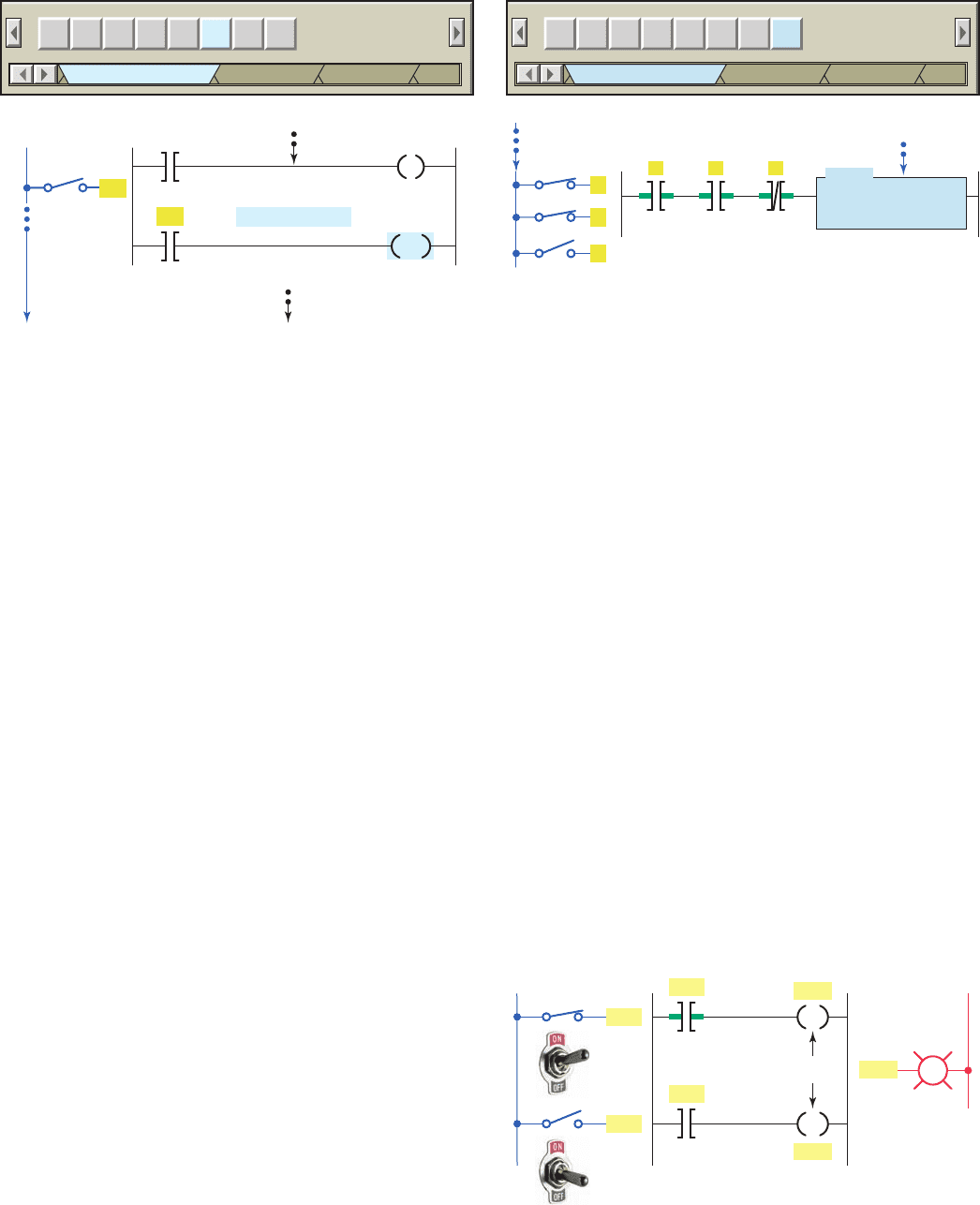
output off. The program of Figure 13-28 illustrates what
Figure 13-26 TND (temporary end) diagnostic instruction.
JMP LBL JSR RET SBR TND
Program Control
Ascii Control Ascii String
MCR SUS
Micro
Main program
Temporary end
L1
Inputs
SW
SW
TND
Reminder of main program
Figure 13-27 SUS (suspend) diagnostic instruction.
JMP LBL JSR RET SBR TND
Program Control
Ascii Control Ascii String
MCR
Micro
A
BC
SUS
Suspend
Suspend ID 100
L1
Inputs
Trapped input conditions
Main program
A
B
C
Figure 13-28 Program with the same address used for
two coils.
OutputLadder logic program
Same address
Inputs
L2
PL
(OFF)
L1
O:2/1
O:2/1
I:1/1
I:1/1
I:1/2
I:1/2
O:2/1
pet10882_ch13_268-290.indd 283pet10882_ch13_268-290.indd 283 7/27/10 6:03 PM7/27/10 6:03 PM
284 Chapter 13 PLC Installation Practices, Editing, and Troubleshooting
happens when the same address is used for two coils. The
resulting problem scenario can be summarized as follows:
• The problem is turning input switch I:1/1 on will
not turn on PL output O:2/1 as it appears to be
programmed.
• The root of the problem lies in the fact that the
PLC scans the program from left to right and top to
bottom.
• Whenever input switch I:1/1 is true (closed) and
input switch I:1/2 is false (open) output O:2/1 will
be off.
• This is because when the PLC updates the outputs it
does so based on the status of input I:1/2.
• Regardless of whether input I:1/1 is open or closed
the output reacts only to the status of input switch
I:1/2.
When a problem occurs, the best way to proceed is to
try to logically identify the devices or connections that
could be causing the problem rather than arbitrarily check-
ing every connection, switch, motor, sensor, I/O module,
and so on. First, observe the system in operation and try
to describe the problem. Using these observations and the
description of the control system, you should identify the
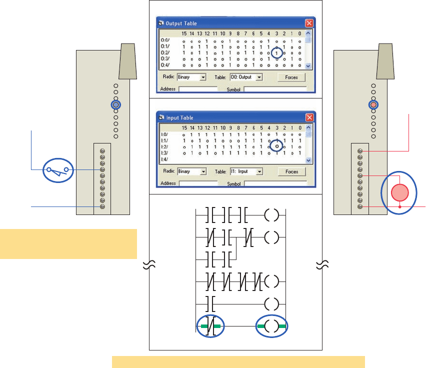
possible sources of trouble. Compare the logic status of
the hardwired inputs and outputs to their actual state, as
illustrated in Figure 13-29 . Any disagreements indicate
malfunctions as well as their approximate location.
Some of your troubleshooting can be accomplished by
interpreting the status indicators on the I/O modules. The
key is to know whether the status indicators are telling
you that there is a fault or that the system is normal. Often
PLC manufacturers supply a troubleshooting guide, map,
or tree that presents a list of observed problems and their
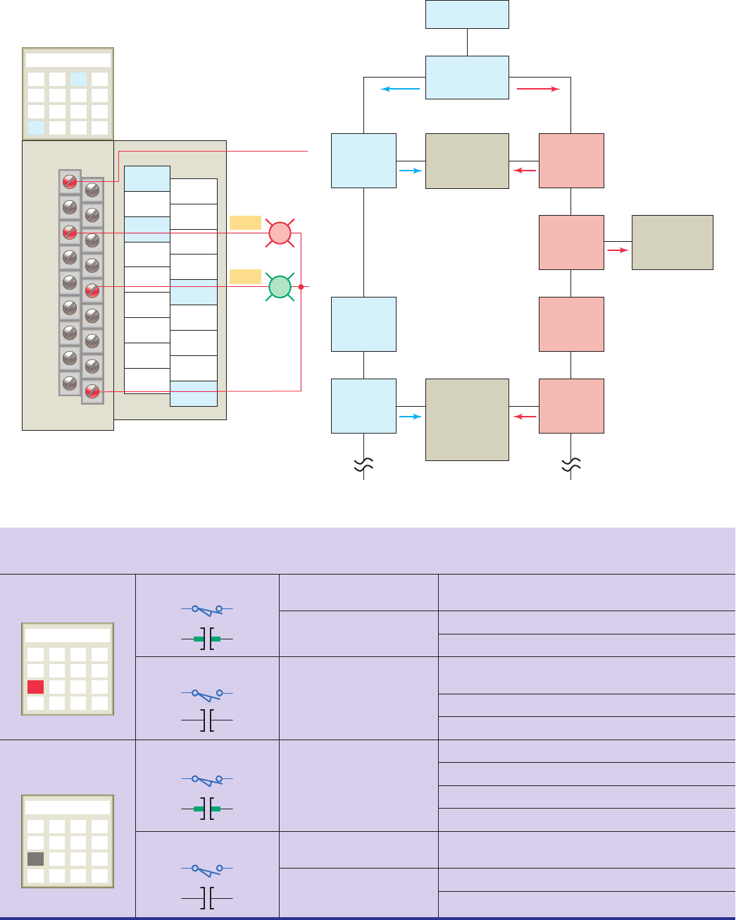
possible sources. Figure 13-30 shows a sample trouble-
shooting tree for a discrete output module. Figures 13-31
and 13-32 are samples of input and output troubleshoot-
ing guides.
Figure 13-29 General methods of troubleshooting.
Logic observation— determine validity of decisions made by processor
User program
True True
Hardware comparison test— compare
state of Ι/O as stored in memory to
actual state
L1
L2
Input
device
Input
module
Open-off
Status
off
L1
L2
Output
module
Status
On
Load
energized
on
Memory
Input image table
Output image table
pet10882_ch13_268-290.indd 284pet10882_ch13_268-290.indd 284 7/27/10 6:03 PM7/27/10 6:03 PM
PLC Installation Practices, Editing, and Troubleshooting Chapter 13 285
OFF
Output
status
indicators
Check Ι/O
device wiring
•
Repair
•
Replace
•
Modules
•
Swing arm
•
Power
•
Rack
Find out why
Ye s
Output module
OFF
Blown fuse
indicator
Display
rung on
screen
No
Ye s
Is output
instruction
true?
Check Ι/O
Output device
would not
ON
Output
status
indicators
Display
rung on
screen
Ye s
Is output
instruction
true?
ON
ON
OFF
Turn OFF
Turn ON
No
Output
0
1
2
3
4
5
6
7
8
9
10
11
12
13
14
15
VAC
Out 1
Out 3
Out 5
Out 7
Out 9
Out 11
Out 13
Out 15
Out 0
Out 2
Out 4
Out 6
Out 8
Out 10
Out 12
Out 14
AC
COM
L1
L2
R
G
O:2/3
O:2/8
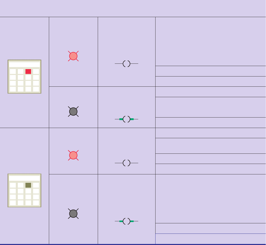
Figure 13-30 Troubleshooting tree for a discrete output module.
If Your Input
Circuit LED Is . . .
And Your Input
Device Is . . . And Probable Cause
ON
Input
0
1
2
3
4
5
6
7
8
9
10
11
12
13
14
15
On/Closed/Activated
Your input device will not
turn off.
Device is shorted or damaged.
Your program operates
as though it is off.
Input circuit wiring or module.
Input is forced off in program.
Off/Open/Deactivated
Your program operates
as though it is on and/or
the input circuit will not
turn off.
Input device off-state leakage current exceeds
input circuit specication.
Input device is shorted or damaged.
Input circuit wiring or module.
OFF
Input
0
1
2
3
4
5
6
7
8
9
10
11
12
13
14
15
On/Closed/Activated
Your program operates
as though it is off and/or
the input circuit will not
turn on.
Input circuit is incompatible.
Low voltage across the input.
Input circuit wiring or module.
Input signal turn-on time too fast for input circuit.
Off/Open/Deactivated
Your input device will not
turn on.
Input device is shorted or damaged.
Your program operates
as though it is on.
Input is forced on in program.
Input circuit wiring or module.
Figure 13-31 Input troubleshooting guide.
pet10882_ch13_268-290.indd 285pet10882_ch13_268-290.indd 285 7/27/10 6:03 PM7/27/10 6:03 PM
286 Chapter 13 PLC Installation Practices, Editing, and Troubleshooting
13.10 PLC Programming Software
You must establish a way for your personal computer
(PC) software to communicate with the programmable
logic controller (PLC) processor. Making this connection
is known as con guring the communications. The method
used to con gure the communications varies with each
brand of controller. In Allen-Bradley controllers, RSLogix
software is required to develop and edit ladder programs.
A second software package, RSLinx, is needed to monitor
PLC activity, download a program from your PC to your
PLC, and upload a program from your PLC into your
PC. You cannot download multiple projects to the PLC
and then run them when required. The PLC will accept
only one program at a time, but the program can consist
of multiple subroutine les which can be conditionally
called from the main program.
RSLinx software is available in multiple packages to
meet the demand for a variety of cost and functionality
requirements. This software package is used as the driver
between your PC and PLC processor. A driver is a com-
puter program that controls a device. For example, you
must have the correct printer driver installed in your PC
Figure 13-32 Output troubleshooting guide.
If Your Output
Circuit LED Is . . .
And Your Output
Device Is . . . And Probable Cause
ON
Output
0
1
2
3
4
5
6
7
8
9
10
11
12
13
14
15
On/Energized
Your program indicates
that the output circuit is
off or the output circuit
will not turn off.
Programming problem:
- Check for duplicate outputs and addresses.
- If using subroutines, outputs are left in their last
state when not executing subroutines.
- Use the force function to force output off. If
this does not force the output off, output circuit
is damaged. If the output does force off, then
check again for logic/programming problem.
Output is forced on in program.
Output circuit wiring or module.
Off/De-energized
Your output device will
not turn on and the
program indicates that
it is on.
Low or no voltage across the load.
Output device is incompatible: check
specications and sink/source compatibility
(if dc output).
Output circuit wiring or module.
OFF
Output
0
1
2
3
4
5
6
7
8
9
10
11
12
13
14
15
On/Energized
Your output device will
not turn off and the
program indicates that
it is off.
Output device is incompatible.
Output circuit off-state leakage current may
exceed output device specication.
Output circuit wiring or module.
Output device is shorted or damaged.
Off/De-energized
Your program indicates
that the output circuit is
on or the output circuit
will not turn on.
Programming problem:
- Check for duplicate outputs and addresses.
- If using subroutines, outputs are left in their last
state when not executing subroutines.
- Use the force function to force output on. If
this does not force the output on, output circuit
is damaged. If the output does force on, then
check again for logic/programming problem.
Output is forced off in program.
Output circuit wiring or module.
pet10882_ch13_268-290.indd 286pet10882_ch13_268-290.indd 286 7/27/10 6:03 PM7/27/10 6:03 PM
PLC Installation Practices, Editing, and Troubleshooting Chapter 13 287
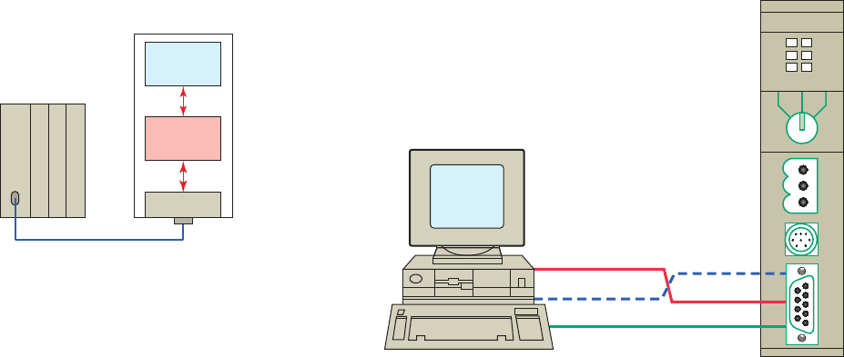
Figure 13-33 Direct PC-to-PLC software connection.
PLC
Personal computer
(PC)
Serial cable
RSLogix
software
RSLinx
software
COM port
Processor
in order to be able to print a word-processing document
created on your PC. RSLinx works much like the printer
driver for RSLogix software. The RSLinx program must
be opened and drivers con gured before communications
can be established between a PC and a PLC that is using
RSLogix software.
RSLinx allows RSLogix to communicate through an
interface cable to the PLC processor. The simplest con-
nection between a PC and a PLC is a point-to-point direct
connection through the computer serial port, as illustrated
in Figure 13-33 . A serial cable is used to connect to your
PC’s COM 1 or COM 2 port and to the PLC processor’s
serial communications port. With RSLinx software you
can auto-con gure the serial connection and thus auto-
matically nd the proper serial port con guration.
Two important aspects of the communication link
must be considered, namely, the RS-232 standard and the
communications protocol. The RS-232 standard speci-
es a function for each of the wires inside the standard
Figure 13-34 Serial wiring connection.
FORCE
SLC 5/04 CPU
RUN
DHFLT
R3232BATT
PROGRUN REM
Send 2
Receive 3
3 Receive
Ground (common) 77
Send
2 Send
communications cable and their associated pins. Commu-
nications protocol is a standardized method for transmit-
ting data and/or establishing communications between
different devices.
Minimum con guration for two-way communications
requires the use of only three connected wires, as shown
in Figure 13-34 . For ease of connection, the RS-232
standard speci es that computer devices have male con-
nectors and that peripheral equipment have female con-
nectors. Direct communication between two computers,
such as a PC and a PLC, does not involve intermediate pe-
ripheral equipment. Therefore, a serial null-modem type
cable must be used for the connection because both the
PC and the PLC processor use pin 2 for data output and
pin 3 for data input.
pet10882_ch13_268-290.indd 287pet10882_ch13_268-290.indd 287 7/27/10 6:03 PM7/27/10 6:03 PM

288 Chapter 13 PLC Installation Practices, Editing, and Troubleshooting
1. Why are PLCs installed within an enclosure?
2. What methods are used to keep enclosure
temperatures within allowable limits?
3. State two ways in which electrical noise may be
coupled into a PLC control system.
4. List three potential noise-generating inductive
devices.
5. Describe four ways in which careful wire routing
can help cut down on electrical noise.
6 . a . What type of input eld devices and output
modules are most likely to have a small
leakage current ow when they are in the off
state? Why?
b. Explain how an input bleeder resistor reduces
leakage current.
7. Summarize the basic grounding requirements for a
PLC system.
8. Under what condition can a ground loop circuit be
developed?
9. When line voltage variations to the PLC power
supply are excessive, what can be done to solve the
problem?
10. What operating state will cause an inductive load to
generate a very high voltage spike?
11. Explain how a diode is connected to suppress a DC
inductive load.
12. Explain how a MOV suppresses an AC inductive
load.
13. What is the purpose of PLC editing functions?
14. What is involved with commissioning a PLC
system?
15. a. Compare of ine and online programming.
b. Which method is safer? Why?
16. List four uses for the data monitor function.
17. What information is provided by the cross refer-
ence function?
18. What information is provided by the contact
histogram function?
19. List ve preventive maintenance tasks that should
be carried out on the PLC installation regularly.
20. Outline the general procedure followed to lock out
and tag a PLC installation.
21. Typically, what does each of the following proces-
sor diagnostic light states indicate?
a. RUN light is off.
b. Fault light is off.
c. BATTERY light is on.
22. When a processor comes equipped with a fault
relay, what are the relay contacts used for?
23. Explain the function of a watchdog timer circuit.
24. A PLC is operating in the RUN mode but output
devices do not operate as programmed. List ve
faults that could be responsible for this condition.
25. What is the verify results function used for?
26. A fast-acting solenoid-operated gate is suspected
of not functioning properly when energized and de-
energized by the PLC program. Explain how you
would use the force function to check its operation.
27. What happens when the processor encounters a
temporary end instruction?
28.
Explain the function of the suspend instruction.
29. In what negative ways can faulty wiring and connec-
tions affect signals sent to and from the I/O modules?
30. The same address is used for two coil instructions
within the same PLC program. What will happen as
a consequence of this?
31. Compare the uses for RSLogix and RSLinx
programming software.
CHAPTER 13 REVIEW QUESTIONS
1. The enclosure door of a PLC installation is not kept
closed. What potential problem could this create?
2. A fuse is blown in an output module. Suggest two
possible reasons why the fuse blew.
CHAPTER 13 PROBLEMS
3. Whenever a crane located over a PLC installation is
started from a standstill, temporary malfunction of
the PLC system occurs. What is one likely cause of
the problem?
pet10882_ch13_268-290.indd 288pet10882_ch13_268-290.indd 288 7/27/10 6:03 PM7/27/10 6:03 PM

PLC Installation Practices, Editing, and Troubleshooting Chapter 13 289
4. During the static checkout of a PLC system, a
speci c output is forced on by the programming
device. If an indicator other than the expected one
turns on, what is the probable problem?
5. The input device to a module is activated, but the
LED status indicator does not come on. A check
of the voltage to the input module indicates that no
voltage is present. Suggest two possible causes of
the problem.
6. An output is forced on. The module logic light
comes on, but the eld device does not work. A
check of the voltage on the output module indi-
cates the proper voltage level. Suggest two possible
causes of the problem.
7. A speci c output is forced on, but the LED module
indicator does not come on. A check of the voltage
at the output module indicates a voltage far below
the normal on level. What is the rst thing to
check?
8. An electronic-based input sensor is wired to
a high-impedance PLC input and is falsely
activating the input. How can this problem be
corrected?
9. An LED logic indicator is illuminated, and
according to the programming device monitor,
the processor is not recognizing the input.
If a replacement module does not eliminate
the problem, what two other items should be
suspected?
10. a. A normally open eld limit switch examined for
an on state normally cycles from on to off ve
times during one machine cycle. How could you
tell by observing the LED status light that the
limit switch is functioning properly?
b. How could you tell by observing the program-
ming device monitor that the limit switch is
functioning properly?
c. How could you tell by observing the LED status
light whether the limit switch was stuck open?
d. How could you tell by observing the program-
ming device monitor whether the limit switch
was stuck open?
e. How could you tell by observing the LED status
light if the limit switch was stuck closed?
f. How could you tell by observing the program-
ming device monitor if the limit switch was
stuck closed?
11. Assume that prior to putting a PLC system into op-
eration, you want to verify that each input device is
connected to the correct input terminal and that the
input module or point is functioning properly. Out-
line a method of carrying out this test.
12. Assume that prior to putting a PLC system
into operation, you want to verify that each
output device is connected to the correct output
terminal and that the output module or point
is functioning properly. Outline a method of
carrying out this test.
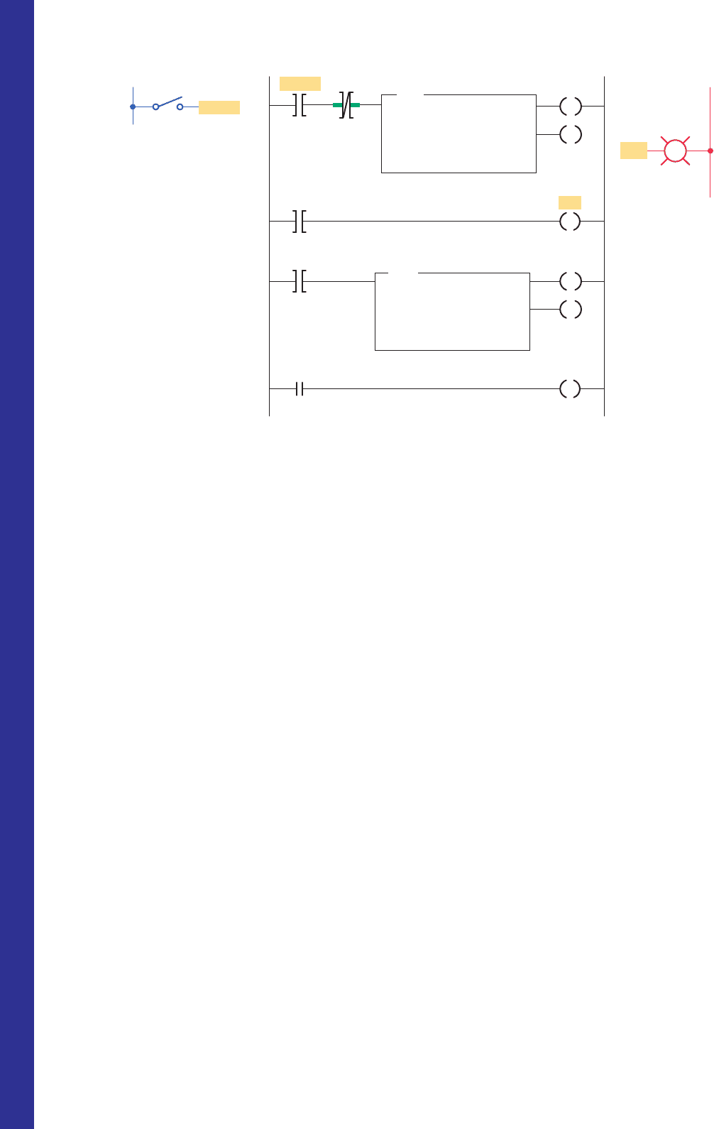
13. With reference to the ladder logic program of
Figure 13-35 , add instructions to modify the
program to ensure that the second pump_2
does not run while pump_1 is running. If this
condition occurs, the program should suspend
operation and enter code identi cation number
100 into S2:7.
14. The program of Figure 13-36 is supposed to
execute to sequentially turn PL1 off for 5 seconds
and on for 10 seconds whenever input A is
closed.
a. Examine the ladder logic and describe how the
circuit would operate as programmed.
b. Troubleshoot the program and identify what
needs to be changed to have it operate properly.
Figure 13-35 Program for Problem 13.
L1
L2
Pump 2
Pump 1
Pump 1
PB1
PB2
OutputsInputs Ladder logic program
PL1
PB2
PB1
Pump 1
Pump 2
PL1
M1
M2
pet10882_ch13_268-290.indd 289pet10882_ch13_268-290.indd 289 7/27/10 6:03 PM7/27/10 6:03 PM
290 Chapter 13 PLC Installation Practices, Editing, and Troubleshooting
Figure 13-36 Program for Problem 14.
T4:2
0.1
50
0
DN
EN
DN
EN
TON
TIMER ON DELAY
Timer
Time base
Preset
Accumulated
T4:3
0.1
100
0
TON
TIMER ON DELAY
Timer
Time base
Preset
Accumulated
PL1
T4:2
T4:2
T4:2
Input A
B3:1
L1
Input
B3:1
0
DN
DN
DN
0
Ladder logic program
Output
L2
Input A
PL1
pet10882_ch13_268-290.indd 290pet10882_ch13_268-290.indd 290 7/27/10 6:03 PM7/27/10 6:03 PM
291
This chapter introduces the kinds of industrial
processes that can be PLC controlled. SCADA
is such a process. Different types of control sys-
tems are used for complex processes. These
control systems may be PLCs, but other control-
lers include robots, data terminals, and comput-
ers. For these controllers to work together, they
must communicate. This chapter will discuss the
different kinds of industrial processes and the
means by which they communicate.
Chapter Objectives
After completing this chapter, you will be able to:
14.1 Discuss the operation of continuous process, batch
production, and discrete manufacturing processes
14.2 Compare individual, centralized, and distributive
control systems
14.3 Explain the functions of the major components of a
process control system
14.4 Describe the various functions of electronic HMI
screens
14.5 Recognize and explain the functions of the control
elements of a closed-loop control system
14.6 Explain how on/off control works
14.7 Explain how PID control works
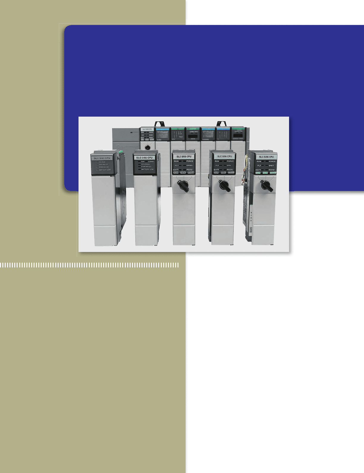
14
Process Control, Network
Systems, and SCADA
Image Used with Permission of Rockwell Automation, Inc.
pet10882_ch14_291-316.indd 291pet10882_ch14_291-316.indd 291 7/27/10 6:15 PM7/27/10 6:15 PM
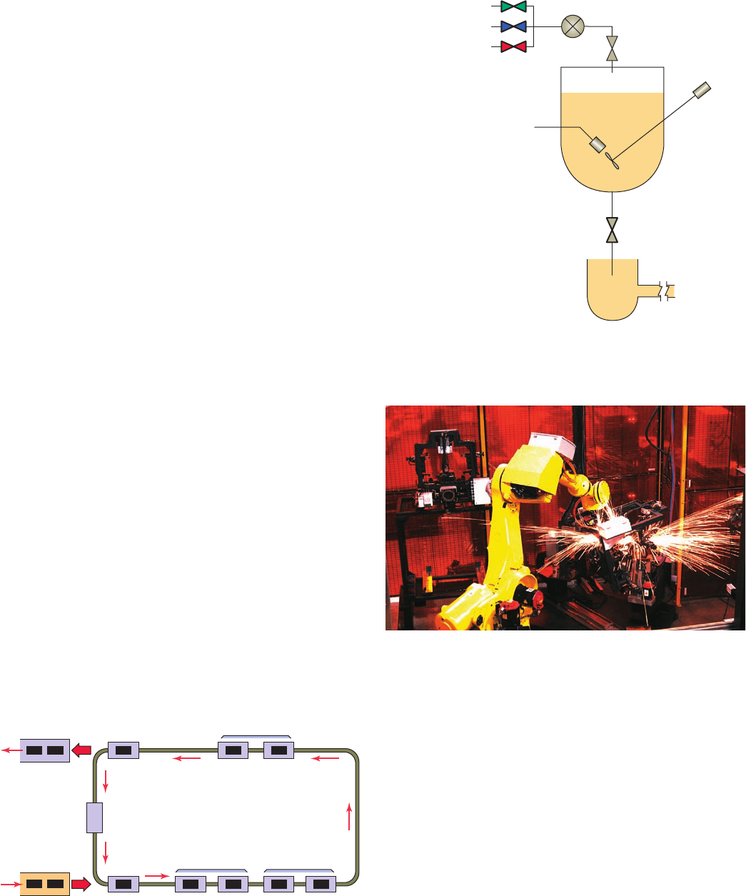
292 Chapter 14 Process Control, Network Systems, and SCADA
car interiors, as illustrated in Figure14-3 , is one example
of discrete manufacturing.
Possible control con gurations include individual,
centralized, and distributed. Individual control is used to
control a single machine. This type of control does not
normally require communication with other controllers.
Figure 14-4 shows an individual control application for
a cut to length operation. The operator enters the feed
length and batch count via the interface control panel and
then presses the start button to initiate the process. Stock
lengths vary so the operator needs to select the length and
the number of pieces to be cut.
14.1 Types of Processes
Process control is the automated control of a process.
Such systems typically deal with analog signals from sen-
sors. The ability of a PLC to perform math functions and
utilize analog signals makes it ideally suited for this type
of control. Manufacturing is based on a series of processes
being applied to raw materials. Typical applications of
process control systems include automobile assembly,
petrochemical production, oil re ning, power generation,
and food processing.
A continuous process is one in which raw materials
enter one end of the system and the nished product comes
out the other end of the system; the process itself runs con-
tinuously. Figure 14-1 shows a continuous process used
in an automotive engine assembly line. Parts are mounted
sequentially, in an assembly-line fashion, through a series
of stations. Assembly and adjustments are carried out by
both automated machine and manual operations.
In batch processing, there is no ow of product mate-
rial from one section of the process to another. Instead, a
set amount of each of the inputs to the process is received
in a batch, and then some operation is performed on the
batch to produce a product. Products produced using the
batch process include food, beverages, pharmaceutical
products, paint, and fertilizer. Figure14-2 shows an ex-
ample of a batch process. Three ingredients are mixed
together, heated, and then stored. Recipes are the key to
producing batches as each batch may have different char-
acteristics by design.
Discrete manufacturing is characterized by individual
or separate unit production. With this manufacturing pro-
cess, a series of operations produces a useful output prod-
uct. Discrete manufacturing systems typically deal with
digital inputs to PLCs that cause motors and robotic de-
vices to be activated. The work piece is normally a discrete
part that must be handled on an individual basis. Making
Figure 14-1 Continuous process.
Automated
machine
assembly
Hand assembly
Adjustments, checks
Completed
engines
Engine
block
Figure 14-2 Batch process.
Material input 2
Material input 1
Mix batch
Heat batch
Heater
Mixer
motor
Flow
meter
Store batch
Material input 3
Figure 14-3 Discrete manufacturing.
Source: Courtesy Automation IG.
pet10882_ch14_291-316.indd 292pet10882_ch14_291-316.indd 292 7/27/10 6:15 PM7/27/10 6:15 PM