Petruzella F.D. Programmable Logic Controllers
Подождите немного. Документ загружается.

Sequencer and Shift Register Instructions Chapter 12 263
The difference between FIFO and LIFO stack opera-
tion is that the LIFO instruction removes data in the re-
verse of the order they are loaded (last in, rst out). An
example of the LIFO instruction pair is shown in Fig-
ure12-36 and the operation of this function can be sum-
marized as follows:
• The load and unload of the LIFO stack operates
similarly to that of the FIFO stack, except that the
last word in the LIFO stack is the rst word that is
unloaded from the stack.
• Words can be added to the LIFO stack without dis-
turbing the words already loaded on the stack.
• Otherwise, LIFO instructions operate the same as
FIFO instructions.
• A false-to-true transition of input B causes all data
in the FIFO le to shift one position toward the
starting address of the le, with the data from the
starting address of the le shifting to the destination
address, N7:11.
The FIFO instruction is often used for inventory con-
trol. One example is where different parts need to be re-
moved from inventory to be used in production. Each part
is assigned a unique code, which is loaded into a FIFO
stack, and parts are removed in the order prescribed by
the stack. This type of control ensures that the oldest part
in the inventory is used rst as the rst part entered is the
rst part removed.
The opposite principle—where the last data to be
stored are the rst to be retrieved—is known as LIFO
(Last In, First Out). The LIFO instruction inverts the order
of the data it receives by outputting the last data received
rst and the rst data received last. A useful analogy is
a pile of work on your desk. As new work arrives you
drop it on the top of the stack. If your stack is LIFO, you
pick your next job from the top of the pile. If your stack
is FIFO, you pick your work from the bottom of the pile.
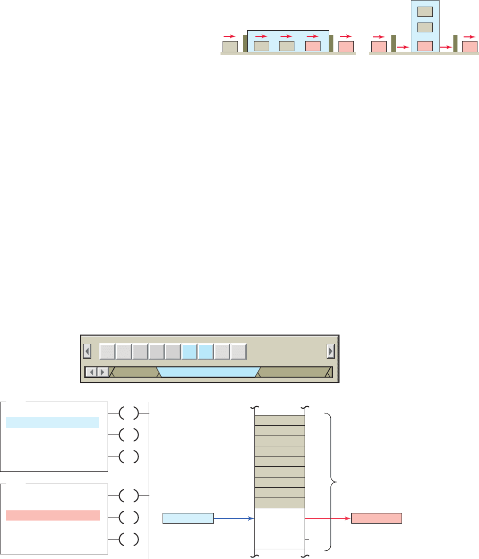
Figure12-35 shows how the FIFO and LIFO operations
work for container stacking operations.
Figure 12-35 FIFO and LIFO container stacking
operations.
Vertical storage area
Out
33
In
LIFO stackHorizontal storage area
3
2
1
Out
In
14
FIFO stack
2 13
Figure 12-36 LIFO instruction pair.
LFL
LIFO LOAD
Source
LIFO
Control
Length
Position
N70:1
#N70:3
R6:61
64
0
LFU
LIFO UNLOAD
LIFO
Dest
Control
Length
Position
#N70:3
N70:2
R6:61
64
0
3
4
5
6
7
8
9
10
11
63
Word
64 words allocated for
LIFO stack at #N70:3
LIFO unload
removes data
from stack in
reverse order.
Destination N70:2
Transfer of data
N70:1 Source
LIFO load enters
data into stack at
next position.
File #N70:3
BSL BSR SQC SQL SQO FFL
File Shift
/
Sequencer
File/Misc Program Control
FFU LFL LFU
EN
DN
EM
EU
DN
EM
pet10882_ch12_242-267.indd 263pet10882_ch12_242-267.indd 263 7/27/10 4:33 PM7/27/10 4:33 PM

264 Chapter 12 Sequencer and Shift Register Instructions
1. Describe the operation of a drum switch.
2. What type of operations are sequencers most
suitable for?
3. Why are PLC sequencers easier to program than
PLC discrete outputs?
4. Answer the following with regard to an SLC 500
PLC sequencer output instruction:
a. Where is the information for each sequencer
step entered?
b. What is the function of the output word?
c. Explain the transfer of data that occurs as the
sequencer is advanced through its various steps.
5. What is the function of the le of a sequencer?
6. What is the function of the mask in the sequencer
instruction?
7. What is the relationship between the length and the
position in a sequencer instruction?
8. What output and step programming limits may be
placed on sequencer instructions?
9. Sequencer instructions are usually retentive.
Explain what this means.
10. Compare the operation of an event-driven and a
time-driven sequencer.
11. Explain the function of a sequencer input and com-
pare instruction.
12. What is the difference between SQI and SQC
instructions?
13. What is the purpose of using the SQI and SQO
instruction in pairs?
14. What is the primary application in which an SQL
instruction is used?
15. Explain the function of a sequencer load
instruction.
16. How does a bit shift register manipulate individual
bits?
17. List four common applications for bit shift
registers.
18. When using a sensor as the input to the bit address
of a BSL instruction, what is its function?
19. Compare the operation of the BSL and BSR bit
shift instructions.
20. A bit shift register is said to operate in a synchro-
nous manner. Explain what this means.
21. What is the function of the unload bit in a BSL
instruction?
22. What is the function of the unload bit in a BSR
instruction?
23. A rst in, rst out word shift register operates in an
asynchronous manner. Explain what this means.
24. Why are both FFL and FFU instructions needed to
perform a FIFO function?
25. Compare the operation a FIFO register and a LIFO
register.
CHAPTER 12 REVIEW QUESTIONS
1. Construct an equivalent sequencer data table for
the four steps of the mechanical drum-operated
sequencer drawn in Figure12-37 .
CHAPTER 12 PROBLEMS
2. Answer the following with reference to the
sequencer le #B3:0 shown in Figure12-38 :
a. Assume that output bit addresses O:2/0 through
O:2/15 are controlling associated output pilot
Figure 12-37 Drum-operated sequencer for Problem 1.
3
1
4
2
Steps
NO
switch
Motor
Peg
pet10882_ch12_242-267.indd 264pet10882_ch12_242-267.indd 264 7/27/10 4:33 PM7/27/10 4:33 PM
Sequencer and Shift Register Instructions Chapter 12 265
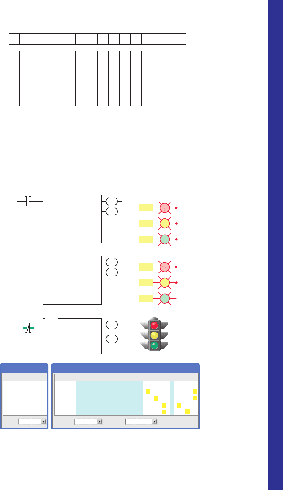
3. Answer each of the following with reference to
the timer-driven sequencer program shown in
Figure12-39 :
a. How many bit outputs are controlled by this
sequencer?
lights PL1 through PL16. State the status of each
light for steps 1 through 4.
b. What output bit addresses could be masked? Why?
c. State the status of each bit of output word O:2 for
step 3 of the sequencer cycle.
Figure 12-38 Sequencer fi le for Problem 2.
0
1
0
0
0
0
1
0
1
1
0
1
0
0
1
0
0
1
1
1
0
1
0
0
1
0
1
0
1
0
0
0
1
0
0
0
1
0
1
0
0
1
0
0
0
0
0
1
1
1
0
1
0
0
1
0
1
0
1
1
0
0
1
0
1
0
0
1
1
0
0
0
1
0
0
0
1
0
1
0
1015 14 13 12 11 10 9 8 7 6 5 4 3 2
Start
Positions
Step 1
Step 2
Step 3
Output
O:2
B3:0
B3:1
B3:2
B3:3
Step 4 B3:4
0000000000000000
Figure 12-39 Timer-driven sequencer program for Problem 3.
Ladder logic program Outputs
L2
O:2/0
O:2/1
O:2/2
T4:1/DN
T4:1/DN
North/South
East/West
SQO
SEQUENCER OUTPUT
File
Mask
Dest
Control
Length
Position
#N7:0
00FFh
O:2
R6:0
4
0
TON
TIMER ON DELAY
Timer
Time base
Preset
Accumulated
T4:1
1.0
25
0
SQO
SEQUENCER OUTPUT
File
Mask
Dest
Control
Length
Position
#N7:10
00FFh
T4:1.PRE
R6:0
4
0
Integer Table
Radix
Decimal
Value
N7:10 0
N7:11 25
N7:12 5
N7:13 25
N7:14 5
Integer Table
Radix
Binary
Table:
N7:Integer
15 14 13 12 11 10 9 8 7 6 5 4 3 2 1 0
N7:0/ 0 0 0 0 0 0 0 0 0 0 0 0 0 0 0 0
N7:1/ 0 0 0 0 0 0 0 0 0 1 0 0 0 0 0 1
N7:2/ 0 0 0 0 0 0 0 0 0 0 1 0 0 0 0 1
N7:3/ 0 0 0 0 0 0 0 0 0 0 0 1 0 1 0 0
N7:4/ 0 0 0 0 0 0 0 0 0 0 0 1 0 0 1 0
EN
DN
EN
DN
EN
DN
O:2/4
O:2/5
O:2/6
pet10882_ch12_242-267.indd 265pet10882_ch12_242-267.indd 265 7/27/10 4:33 PM7/27/10 4:33 PM

266 Chapter 12 Sequencer and Shift Register Instructions
c. Assume that the sequencer is stepped to position
8; what bit outputs will be on?
d. Assume that the sequencer is at position 8 and a
true-to-false transition of one of the inputs occurs.
What happens as a result?
5. Using whatever PLC sequencer output instruction
you are most familiar with, develop a program that
will operate the cylinders in the desired sequence.
The time between each step is to be 3seconds.
The desired sequence of operation will be as
follows:
• All cylinders to retract.
• Cylinder 1 advance.
• Cylinder 1 retract and cylinder 3 advance.
• Cylinder 2 advance and cylinder 5 advance.
• Cylinder 4 advance and cylinder 2 retract.
• Cylinder 3 retract and cylinder 5 retract.
• Cylinder 6 advance and cylinder 4 retract.
• Cylinder 6 retract.
• Sequence to repeat.
6. Using whatever PLC sequencer output instruction
you are most familiar with, develop a program to im-
plement an automatic car-wash process. The process
is to be event-driven by the vehicle, which activates
b. What is the address of the word that controls the
outputs?
c. What is the address of the sequencer le that sets
the states for the outputs?
d. What is the address of the sequencer le that con-
tains the preset timer values?
e. For what length of time is the red light
programmed to be on?
f. For what length of time is the green light
programmed to be on?
g. For what length of time is the yellow light
programmed to be on?
h. What is the time required for one complete cycle
of the sequencer?
i. Assume that the decimal value stored in N7:13
is changed to 35. Outline the changes that this
new value will have on the timing of the traf c
lights.
4. Answer each of the following with reference to
the event-driven sequencer program shown in
Figure12-40 :
a. When does the sequencer advance to the next step?
b. Assume that the sequencer is at position 2, as
shown; what bit outputs will be on?
Figure 12-40 Event-driven sequencer program for Problem 4.
L1
Inputs Ladder logic program
S1
#B3:0
F0FF
O:2
R6:0
8
2
SQO
SEQUENCER OUTPUT
File
Mask
Dest
Control
Length
Position
EN
DN
S1
S2
S2
0
1
2
3
4
5
6
7
8
9
10
11
12
13
14
15
Output
module O:2
Current
step
Pos 2
0
1
2
3
4
5
6
7
8
015 1110 9 8
O:2
Mask
File
Pos
#B3:0
Destination
0
0
0
1
0
0
0
0
0
0
0
0
1
0
0
0
0
1
0
1
0
0
0
0
1
0
0
0
1
0
0
0
0
1
1
1
0
0
0
0
0
0
0
0
0
0
0
0
0
0
0
0
0
0
0
0
0
0
0
0
0
0
0
0
0
0
0
0
0
0
0
0
0
0
0
1
1
1
1
0
0
0
0
0
1
1
1
1
0
1
0
1
0
0
1
0
1
0
0
0
1
0
0
1
0
1
1
1
0
0
000 00001111
1111000011111111
Pos
0
0
1
1
1
0
1
1
0
0
0
1
1
1
0
1
1
1
0
1
1
0
1
0
1
1
0
0
1
1
0
1
0
1
1
1
L2
pet10882_ch12_242-267.indd 266pet10882_ch12_242-267.indd 266 7/27/10 4:33 PM7/27/10 4:33 PM

Sequencer and Shift Register Instructions Chapter 12 267
• If the product is defective, reject status lights come
on at stations 1, 2, and 3 to tell the assembler to
ignore the part.
• When a defective part reaches station 4, a diverter
gate is activated to direct that part to a reject bin.
• Using whatever PLC bit shift register you are most
familiar with, develop a program to implement this
process.
various limit switches (LS1 through LS6) as it is
pulled by a conveyor chain through the car-wash
bay. Design the program to operate the car wash in
the following manner:
• The vehicle is connected to the conveyor chain and
pulled inside the car-wash bay.
• LS1 turns on the water input valve.
• LS2 turns on the soap release valve, which
mixes with the water input valve to provide a
wash spray.
• LS3 shuts off the soap valve, and the water input
valve remains on to rinse the vehicle.
• LS4 shuts off the water input valve and activates
the hot wax valve, if selected.
• LS5 shuts off the hot wax valve and starts the air-
blower motor.
• LS6 shuts off the air blower. The vehicle exits the
car wash.
7. A product moves continuously down an
assembly line that has four stations, as shown in
Figure12-41 .
• The product enters the inspection zone, where its
presence is sensed by the proximity switch.
• The inspector examines it and activates a reject
button if the product fails inspection.
Figure 12-41 Assembly line program for Problem 7.
Station
1
Reject
lamp
status
Product
Proximity
switch
Inspection zone
Gate
Station
2
Station
3
Station
4
Reject
lamp
status
Reject
lamp
status
pet10882_ch12_242-267.indd 267pet10882_ch12_242-267.indd 267 7/27/10 4:33 PM7/27/10 4:33 PM

268
13
PLC Installation Practices,
Editing, and Troubleshooting
Chapter Objectives
After completing this chapter, you will be able to:
13.1 Outline and describe requirements for a
PLCenclosure
13.2 Identify and describe noise reduction techniques
13.3 Describe proper grounding practices and preventive
maintenance tasks associated with PLC systems
13.4 List and describe speci c PLC troubleshooting
procedures
This chapter discusses guidelines for the instal-
lation, maintenance, and troubleshooting of a
PLC-controlled system. The chapter gives you
information on proper grounding that ensures
personal safety as well as correct operation of
equipment. Unique troubleshooting procedures
that apply specifi cally to PLCs are listed and
explained.
Image Used with Permission of Rockwell Automation, Inc.
pet10882_ch13_268-290.indd 268pet10882_ch13_268-290.indd 268 30/07/10 2:08 PM30/07/10 2:08 PM
PLC Installation Practices, Editing, and Troubleshooting Chapter 13 269
provides adequate room within the enclosure is usually
suf cient for heat dissipation. The temperature inside
the enclosure must not exceed the maximum operating
temperature of the controller (typically 60°C maximum).
Additional cooling provisions, such as a fan or blower,
may be required where high internal or ambient tem-
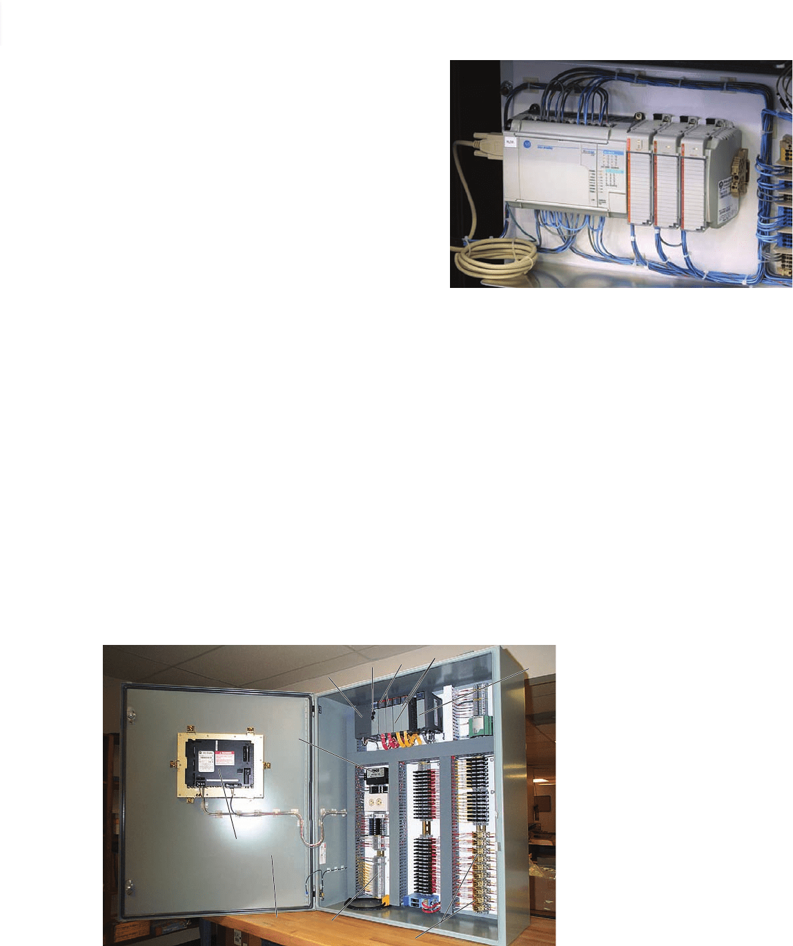
peratures are encountered. PLCs are always mounted
horizontally with the name of the manufacturer fac-
ing out and right-side up, as illustrated in Figure 13-2 .
Vertical mounting is not recommended due to thermal
considerations.
A hardwired electromechanical master control relay
(MCR) is normally included as part of the wiring for a
13.1 PLC Enclosures
A PLC system, if installed properly, should give years of
trouble-free service. The design of PLCs includes a num-
ber of rugged features that allow them to be installed in
almost any industrial environment. However, problems
can occur if the system is not installed properly.
Programmable logic controllers (PLCs) require protec-
tion against temperature extremes, humidity, dust, shock,
and vibration or corrosive environments. For these rea-
sons, PLCs are generally mounted within a machine or in
a separate enclosure as shown in Figure 13-1 .
An enclosure is the chief protection from atmospheric
conditions. The National Electrical Manufacturers Asso-
ciation (NEMA) has de ned enclosure types, based on
the degree of protection an enclosure will provide. For
most solid-state control devices, a NEMA 12 enclosure
is recommended. This type of enclosure is for general-
purpose areas and is designed to be dust-tight. Typically,
metal enclosures are used because metal enclosures pro-
vide shielding that helps minimize the effects of electro-
magnetic radiation that may be generated by surrounding
equipment.
Every PLC installation will dissipate heat from its
power supplies, local I/O racks, and processor. This heat
accumulates in the enclosure and must be dissipated
from it into the surrounding air. Excessive heat can
cause erratic operation of the PLC or PLC failure. For
many applications, normal convection cooling will keep
the controller components within the speci ed tempera-
ture operating range. Proper spacing of components that
Figure 13-2 PLCs are always mounted horizontally.
Source: Courtesy Rogers Machinery Company, Inc.
10.
9.
7.
8.
6.
1.
2. 3.
4.
1.
2.
3.
4.
5.
6.
7.
8.
9.
10.
Power supply
PLC (programmable logic controller)
Digital input cards
Digital output cards
Analog input cards
Transient surge protectors
Circuit breakers
Relay switches
Operator interface terminal
NEMA 12 enclosure
5.
Figure 13-1 Typical PLC control panel enclosure.
Source: Courtesy Aaron Associates.
pet10882_ch13_268-290.indd 269pet10882_ch13_268-290.indd 269 7/27/10 6:02 PM7/27/10 6:02 PM
270 Chapter 13 PLC Installation Practices, Editing, and Troubleshooting
MCR is connected to interrupt power to the I/O rack in the
event of an emergency, but still allow power to be main-
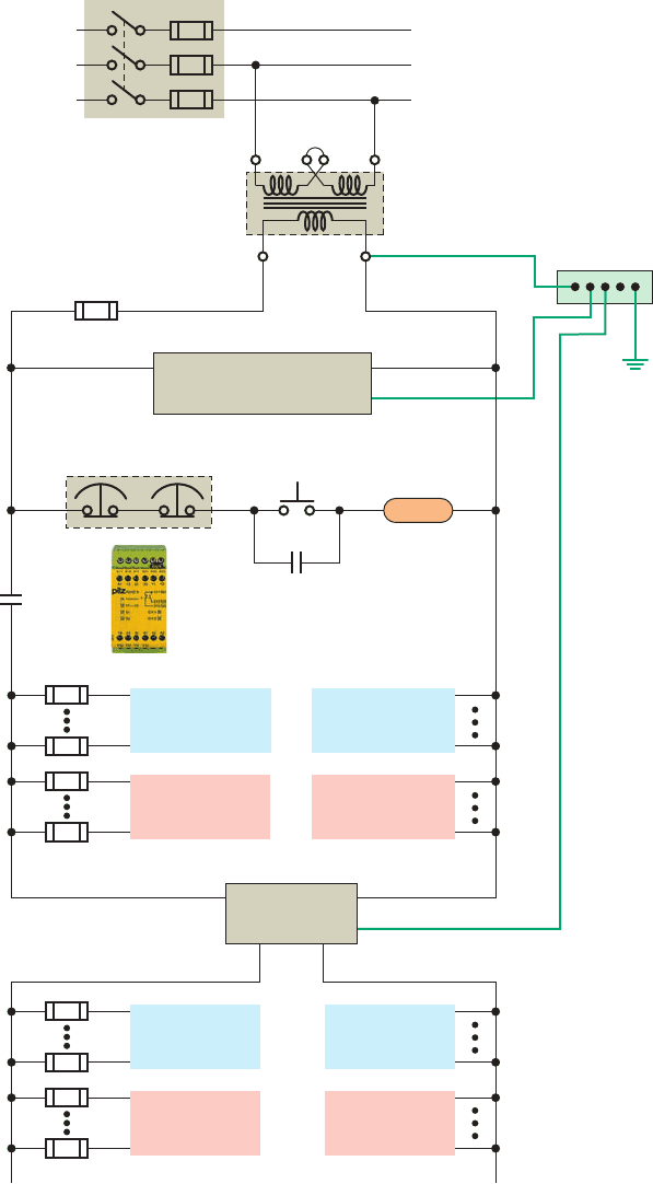
tained at the processor. Figure 13-3 shows the typical wir-
ing for an AC power distribution with a master control
PLC system. The master control relay provides a means
of de-energizing the entire circuit that is not dependent on
software. The internally programmed MCR of a PLC is
not suf cient to meet safety requirements. The hardwired
Figure 13-3 Typical wiring for an AC power distribution with a master
control relay.
Source: Courtesy Pilz GmbH & Co. KG.
To V of DC
input devices
DC power
supply
To V of DC
output modules
To common
of DC input
modules
To common
of DC output
devices
To common (L1)
of 120 v AC
input devices
MCR
Multiple E-stops
Start
L1
Fuse
L1
N
Panel
ground bus
Grounding
electrode
120 V
X1
H
3
H
2
H
4
H
1
X2
Neutral
Disconnect switch
3-phase
supply
Step-down
transformer
Gnd
MCR
MCR
To L1
of 120 v AC
output modules
To neutral conn.
of 120 v AC
input modules
To neutral
of 120 v AC
output devices
L1 N
Gnd
DC commonV
Processor power supply
pet10882_ch13_268-290.indd 270pet10882_ch13_268-290.indd 270 7/27/10 6:02 PM7/27/10 6:02 PM
PLC Installation Practices, Editing, and Troubleshooting Chapter 13 271
• Proper routing of wiring
• Proper suppression added to noise-generating devices
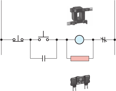
Noise suppression is normally needed for inductive
loads such as relays, solenoids, and motor starters when
operated by hard contact devices such as pushbuttons or
selector switches. When inductive loads are switched off,
high transient voltages are generated that if not suppressed
can reach several thousand volts. Figure 13-4 illustrates a
typical noise suppression circuit that is used to suppress
the high voltage spikes generated when a motor starter
coil is de-energized.
Lack of surge suppression on inductive loads may con-
tribute to processor faults and sporadic operation. RAM
can be corrupted (lost), and I/O modules can appear faulty
or can reset themselves. When inductive devices are ener-
gized or de-energized, they can cause an electrical pulse
to be back-fed into the PLC system. The back-fed pulse,
when entering the PLC system, can be mistaken by the
PLC for a computer pulse. It takes only one false pulse
to create a malfunction of the orderly ow of PLC opera-
tional sequences.
Proper routing of eld power and signal wiring to the
PLC enclosure as well as inside the enclosure helps to cut
down on electrical noise. The following are some general
guidelines for PLC wire routing:
• Use the shortest possible wire runs for I/O signals.
• When possible, conductors that are run from the
PLC enclosure to another location should be in a
metal conduit as the metal can serve as a shield
against EMI.
• Never run signal wiring and power wiring in the
same conduit.
• Segregate I/O wiring by signal type. Route AC and
DC I/O signal wires in separate wireways.
relay. The operation of the circuit can be summarized as
follows:
• A power disconnect switch is provided so that,
when required, the PLC can be serviced with the
power off.
• The step-down transformer provides isolation
from the main power distribution system and
decreases the voltage to the 120 volts required
for the controller power supplies and DC power
supplies.
• The momentary start button is pressed to energize
the master control relay.
• Pressing any one of the emergency-stop switches
de-energizes the master control relay and thus de-
energizes the I/O devices.
• Power to the processor of the PLC remains on so
status LEDs can continue to provide up-to-date
information.
• Emergency stop buttons use normally closed
contacts wired in series for fail-safe operation.
Inthe event a wire is broken or comes off a termi-
nal, the MCR relay is de-energized and power is
removed.
13.2 Electrical Noise
Electrical noise, also called electromagnetic interference,
or EMI, is unwanted electrical signals that produce unde-
sirable effects and otherwise disrupt the control system
circuits. EMI may be either radiated or conducted. Radi-
ated noise originates from a source and travels through
the air while conducted noise travels on an actual conduc-
tor, such as a power line.
When the PLC is operated in a noise-polluted indus-
trial environment, special consideration should be given
to possible electrical interference. To increase the operat-
ing noise margin, the controller should be located away
from noise-generating devices such as large AC motors
and high-frequency welders. Malfunctions resulting from
noise are temporary occurrences of operating errors that
can result in hazardous machine operation in certain ap-
plications. Noise usually enters through input, output,
and power supply lines. Noise may be coupled into these
lines by an electrostatic eld or through electromagnetic
induction. The following reduce the effect of electrical
interference:
• Manufacturer design features
• Proper mounting of the controller within an
enclosure
• Proper equipment grounding
Figure 13-4 Motor starter noise suppression.
Source: Image Used with Permission of Rockwell Automation, Inc.
Noise
suppressor
Stop
L1 L2
Starter
coil
Start
M
OL
M
pet10882_ch13_268-290.indd 271pet10882_ch13_268-290.indd 271 7/27/10 6:02 PM7/27/10 6:02 PM
272 Chapter 13 PLC Installation Practices, Editing, and Troubleshooting
• Low-level signal conductors such as thermocou-
ples and serial communications should be run as
shielded twisted pair and routed separately.
• A ber optic system, which is totally immune to all
kinds of electrical interference, can also be used for
signal wiring.
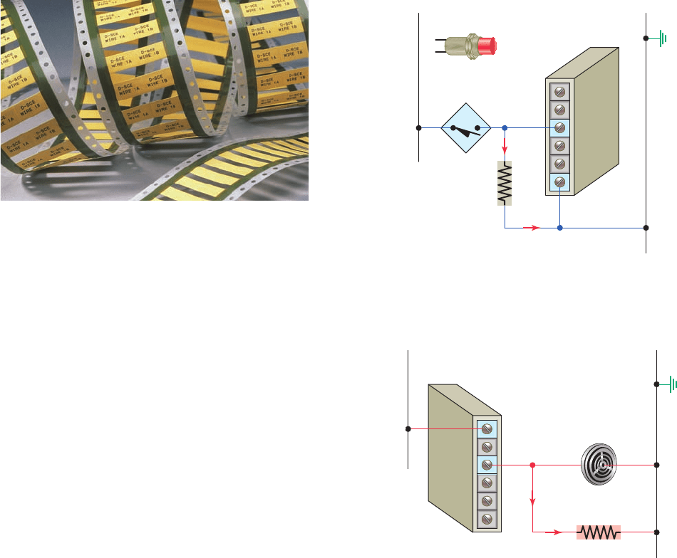
An important part of a PLC installation is clearly iden-
tifying each wire to be connected and the terminal to
which it is connected. A reliable labeling method, such
as the heat-shrinkable wire identi cation sleeves shown
in Figure 13-5 , should be used to label each wire. Wir-
ing connectors for input/output modules usually includes
spaces for labels used for identifying each I/O address and
device connected. Proper wire and terminal identi cation
will simplify the installation and aid in troubleshooting
and maintenance.
13.3 Leaky Inputs and Outputs
Many electronic devices with transistor or triac outputs
exhibit a small leakage current even when in the off state
that may need to be considered when they are connected
to PLC input modules. This so-called leakage is typi-
cally exhibited by two-wire proximity, photoelectric, and
other such sensors. Often, the leaky input will only cause
the module’s input indicator to icker. However, a large
enough leakage current can activate the input circuit, cre-
ating a false input signal.
A common solution to the problem of leaky input cur-
rent is to connect a bleeder resistor across or in parallel
with the input, as shown in Figure 13-6 . The bleeder re-
sistor acts as an additional lower resistance load, which
allows the leakage current to ow through the lower resis-
tance path. Typically a 10 kΩ to 20 kΩ resistor is used to
solve the problem.
Leakage current may also occur with the solid-state
switch used in many output modules. Problems similar to
that encountered with input modules can be created when
a high-impedance load device is used with these modules.
For example, a PLC output might supply a sound alert
device as illustrated in Figure 13-7 . In this case the leak-
age current could cause continuous false or intermittent
operation. A resistor can be connected as shown to bleed
off this current. An isolation relay could also be used to
solve this type of problem.
13.4 Grounding
Proper grounding is an important safety measure in
all electrical installations. The authoritative source on
grounding requirements for a PLC installation is the
National Electrical Code. The NEC specifies the types
Figure 13-5 Heat-shrinkable wire identifi cation sleeves.
Source: Photo courtesy Tyco Electronics, www.tycoelectronics.com.
Figure 13-6 Bleeder resistor connection for input sensors.
Bleeder
resistor
Leakage
current
Input module
N
2-wire
proximity
switch
L1
Common
Figure 13-7 Bleeder resistor connection for a high-
impedance output.
Leakage
current
Bleeder
resistor
Output
module
N
High-
impedance
load
L1
L1
pet10882_ch13_268-290.indd 272pet10882_ch13_268-290.indd 272 7/27/10 6:02 PM7/27/10 6:02 PM