Petruzella F.D. Programmable Logic Controllers
Подождите немного. Документ загружается.


Process Control, Network Systems, and SCADA Chapter 14 313
ef ciency. In general, unlike distributive control systems,
a SCADA system usually refers to a system that coordi-
nates but does not control processes in real time .
In a typical SCADA system, independent PLCs per-
form I/O control functions on eld devices while being
supervised by a SCADA/HMI software package running
connectors or wiring practices such that disconnection of
a single device is possible without disrupting the continu-
ity of the whole segment.
PROFIBUS-DP
PROFIBUS-DP (where DP stands for Decentralized
Periphery) is an open, international eldb
us communi-
cation standard that supports both analog and discrete
signals. It is functionally comparable to DeviceNet.
The physical media are de ned via the RS-485 or ber
optic transmission technologies. PROFIBUS-DP com-
municates at speeds up to 12 Mbps over distances up to
1200 meters. Figure14-46 illustrates a Siemens S7-200
Micro PLC system connection to a PROFIBUS-DP
network.
14.7 Supervisory Control
andData Acquisition (SCADA)
In some applications, in addition to its normal control
functions, the PLC is responsible for collecting data,
performing the necessary processing, and structuring the
data for generating reports. As an example, you could
have a PLC count parts and automatically send the data to
a spreadsheet on your desktop computer.
Data collection is simpli ed by using a SCADA (su-
pervisory control and data acquisition) system, shown in
Figure14-47 . Exchanging data from the plant oor to a
supervisory computer allows data logging, data display,
trending, downloading of recipes, setting of selected pa-
rameters, and availability of general production data. The
additional supervisory control output capabilities allow
you to tweak your processes accurately for maximum
Figure 14-46 Micro PLC system connection to a PROFIBUS-DP network.
Source: Courtesy Siemens.
PROFIBUS-DP
module
PROFIBUS-DP
Figure 14-47 Supervisory control and data acquisition
(SCADA).
Alarms
PLC relay
controls
Analog
outputs
PID
process
control
Printer
Tables and
graphs
Hardcopy
Spreadsheet
Temperature
thermocouples
and resistance
temperature detectors
Pressure
Position
Force
Strain
Speed
Signal sources
Interface
system
Output loads
Computer
pet10882_ch14_291-316.indd 313pet10882_ch14_291-316.indd 313 7/27/10 6:15 PM7/27/10 6:15 PM
314 Chapter 14 Process Control, Network Systems, and SCADA
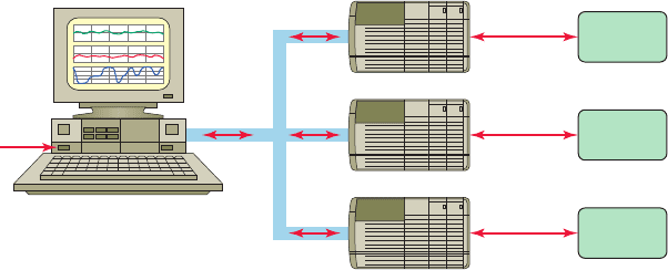
Figure 14-48 Typical SCADA system.
Host computer
SCADA/HMI
software
Data
transfer
I/O
control
Field
devices
I/O
control
Field
devices
I/O
control
Field
devices
PLC
PLC
PLC
on a host computer, as illustrated in Figure 14-48 . Pro-
cess control operators monitor PLC operation on the
host computer and send control commands to the PLCs
if required. The great advantage of a SCADA system is
that data are stored automatically in a form that can be
retrieved for later analysis without error or additional
work. Measurements are made under processor control
and then displayed onscreen and stored to a hardcopy. Ac-
curate measurements are easy to obtain, and there are no
mechanical limitations to measurement speed.
pet10882_ch14_291-316.indd 314pet10882_ch14_291-316.indd 314 7/27/10 6:15 PM7/27/10 6:15 PM

Process Control, Network Systems, and SCADA Chapter 14 315
1. Compare continuous and batch processes.
2. Compare centralized and distributive control
systems.
3. State the basic function of each of the following as
part of a process control system:
a. Sensors
b. Human-machine interface
c. Signal conditioning
d. Actuators
e. Controller
4. State the purpose of each of the following types of
screens associated with HMIs:
a. Trend values
b. Operational summary
c. Alarm summary
5. What is the main characteristic of a closed-loop
control system?
6. State the function of each of the following parts of
a closed-loop control system:
a. Set-point
b. Process variable
c. Error ampli er
d. Controller
e. Output actuator
7. Explain how on/off control works.
8. How does the proportional controller eliminate the
cycling associated with on/off control?
9. Explain how a motor-driven control valve action
can provide analog control.
10. How does time proportioning provide analog
control?
11. What process error or deviation is produced by a
proportional controller?
12. What term of a PID control is designed to eliminate
offset?
13. What does the derivative action of a controller
respond to?
14. List the three gain adjustments used in tuning the
response of a PID control loop.
15. Compare manual, autotune, and intelligent tuning
of a PID controller.
16. How many input and output values are normally
referenced in a PLC PID instruction?
17. What information is contained in the process
variable and control variable elements of a PID
instruction?
18. State the function of each of the following elements
of a PLC motion control system:
a. Programmable controller
b. Motion module
c. Servo drive
d. Servo motor
19. What does each axis of a robot arm function as?
20. List four types of communication tasks provided by
local area networks.
21. Name three common types of transmission media.
22. What are the three general levels of functionality of
industrial networks?
23. D e
ne the term node
as it applies to a network.
24. Explain the physical layout of devices on a network
for each of the following network topologies:
a. Star
b. Bus
25. Compare device and process bus networks.
26. D e ne the term protocol as it applies to a network.
27. What is the function of a network gateway?
28. D e ne the term access method as it applies to a
network.
29. Summarize the token passing network access method.
30. Summarize the collision detection network access
method.
31. Summarize the polling network access method.
32. Compare parallel and serial data transmission.
33. Compare half-duplex and full-duplex data
transmission.
34. Explain how networking schemes minimize the
amount of wiring required.
35. What type of access control is used with DH+?
36. Compare the transmitting distances of RS-232
andRS-422/485 serial types.
37. What is DeviceNet used for?
38. List three pieces of information obtained from
DeviceNet devices by the network scanner.
39. What is ControlNet used for?
CHAPTER 14 REVIEW QUESTIONS
pet10882_ch14_291-316.indd 315pet10882_ch14_291-316.indd 315 7/27/10 6:15 PM7/27/10 6:15 PM

316 Chapter 14 Process Control, Network Systems, and SCADA
44. What is Fieldbus used for?
45. Summarize the two main functions of a SCADA
system.
46. In what way does distributive control differ from
the supervisory control of a SCADA system?
40. Explain how redundant media works.
41. D e ne the term bandwidth as it applies to a
network.
42. What is Ethernet/IP used for?
43. What type of protocol does Modbus use?
1. Distributive control systems have to be network
based. Why?
2. Assume an alarm is sounded in a control system
with an electronic HMI interface. How would you
proceed to identify and solve the problem?
3. How would an on/off controller respond if the dead-
band were too narrow?
4. In a home heating system with on/off control, what
will be the effect of widening the deadband?
5. a. Calculate the proportional band of a temperature
controller with a 5% bandwidth and a set-point of
500°F.
CHAPTER 14 PROBLEMS
b. Calculate the upper and lower limits beyond
which the controller functions as an on/off
unit.
6. Explain the advantage of using a 4- to 20-mA
current loop as an input signal compared to a 0- to
5-V input signal.
7. What does the term deterministic mean, and why is
it important in industrial communications?
8. How might a SCADA system be applied to deter-
mine the production rate of a bottled product over a
two-week period?
pet10882_ch14_291-316.indd 316pet10882_ch14_291-316.indd 316 7/27/10 6:15 PM7/27/10 6:15 PM
317
system, CompactLogix system, FlexLogix sys-
tem, SoftLogix 5800 controller, and DriveLogix
system. Software is the essential difference
between PACs and PLCs. Basically, the ladder
logic confi guration does not change but the
addressing of the instructions changes. Applica-
tion of the software that pertains to the Logix
control platform of controllers will be covered in
the various sections of this chapter. Knowledge
of basic ladder logic instructions and functions
(bit, timer, counter, etc.) covered in previous
chapters of the text is assumed and is thus not
repeated in this chapter.
Programmable logic controllers continue to
evolve as new technologies are added to their
capabilities. The PLC started out as a replace-
ment for banks of relays used to turn outputs
on and off as well as for timing and counting
functions. Gradually, various math and logic
manipulation functions were added. In order to
serve today’s expanding industrial control system
needs, leading automation companies have cre-
ated a new class of industrial controllers called
programmable automation controllers or PACs
( Figure 15-1 ). They look like PLCs in their physi-
cal appearance but incorporate advanced control
of communication, data logging, and signal pro-
cessing, motion, process control, and machine
vision in a single programming environment.
The Allen-Bradley programmable automa-
tion controller family includes the ControlLogix
15
ControlLogix Controllers
Figure 15-1 Programmable automation controllers (PACs).
Source: Image Used with Permission of Rockwell Automation, Inc.
pet10882_ch15_317-372.indd 317pet10882_ch15_317-372.indd 317 7/27/10 6:42 PM7/27/10 6:42 PM
318
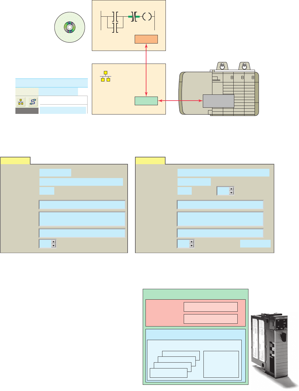
RSLogix 5000 programming software is used to set
up or con gure the memory organization of an Allen-
Bradley ControlLogix controller. RSLinx communication
software is used to set up a communications link between
RSLogix 5000 programming software and the Control-
Logix hardware as illustrated in Figure 15-3 . To estab-
lish communications with a controller, a driver must be
created in RSLinx software. This driver functions as the
software interface to a hardware device. The RSWho is the
network browse interface that provides a single window
to view all con gured network drivers.
Figure 15-4 shows an example of the ControlLogix’s
controllers properties and modules properties dialog
boxes used as part of the con guration process. The
parameters shown are typical of what general informa-
tion is required. After rst con guring the controller,
Memory Layout
ControlLogix processors provide a exible memory struc-
ture. There are no xed areas of memory allocated for
speci c types of data or for I/O. The internal memory orga-
nization of a ControlLogix controller is con gured by the
user when creating a project with RSLogix 5000 software
( Figure 15-2 ). This feature allows the program data to be
constructed to meet the needs of your applications rather
than requiring your application to t a particular memory
structure. A ControlLogix (CLX) system can consist of
anything from a stand-alone controller and I/O modules in
a single chassis, to a highly distributed system consisting
of multiple chassis and networks working together.
Confi guration
Con guration of a modular CLX system involves es-
tablishing a communications link between the control-
ler and the process. The programming software needs to
know what CLX hardware is being used in order to be
able to send or receive data. Con guration information
includes information about the type of processor and I/O
modules used.
Part Objectives
After completing this part, you will be able to:
• Outline project organization
• De ne tasks, programs, and routines
• Identify data le types
• Organize and apply the various data le types
Part 1 Memory and
Project Organization
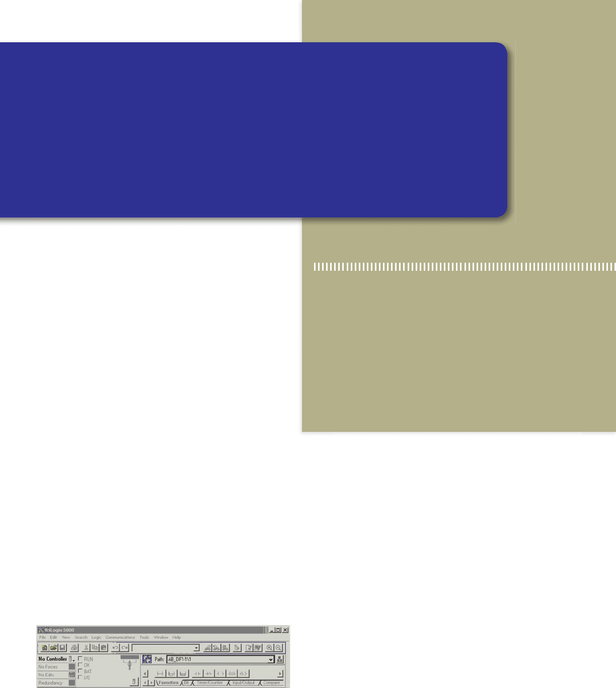
Figure 15-2 RSLogix 5000 screen.
pet10882_ch15_317-372.indd 318pet10882_ch15_317-372.indd 318 7/27/10 6:42 PM7/27/10 6:42 PM
Memory and Project Organization Part 1 319
the I/O modules are con gured using RSLogix 5000
software. Modules will not work unless they have been
properly con gured. The software contains all the hard-
ware information needed to con gure any ControlLogix
module.
Project
RSLogix software stores a controller’s programming and
con guration information in a le called a project. The
block diagram of the processor’s project le is shown in
Figure 15-5 . A project le contains all information relat-
ing to the project. The main components of the project le
are tasks, programs, and routines. A controller can hold
and execute only one project at a time.
Figure 15-5 ControlLogix processor program fi le.
Source: Image Used with Permission of Rockwell Automation, Inc.
Project
Controller tags
(global data)
Other routines
Program tags
(local data)
I/O data
System-shared data
Task
Main routine
Program
Figure 15-3 RSLinx and RSLogix software.
RSLogix
Ladder logic program
RSLinx
File View Communications
RSLinx
RSLogix
RSWho
RSWho
Configure Drivers...
5000
ControlLogix
Controller
Figure 15-4 Controllers properties and modules properties dialog boxes.
Controllers propertiesGeneral
Vendor:
Type:
Revision:
Allen-Bradley
1756-L55ControlLogix5555Controller
10.24
Name:
Description:
Chassis Type:
Slot: 1
Controller 1
Prime Controller
1756-A7 7-Slot Chassis
Modules propertiesGeneral
Type:
Vendor:
Parent:
1756-IB16 16 Point 10V-31.2V DC Input
Allen-Bradley
Local
Name:
Description:
Comm Form:
Revision:
Electronic Keying Exact Match1
Digital_Input_16pt
Optional
Input Data
Slot: 0
pet10882_ch15_317-372.indd 319pet10882_ch15_317-372.indd 319 7/27/10 6:42 PM7/27/10 6:42 PM
320 Part 1 Memory and Project Organization
The RSLogix 5000 controller organizer ( Figure 15-6 )
displays the project organization in a tree format showing
tasks, programs, routines, data types, trends, I/O con gu-
ration and tags. Each folder groups common functions
together. This structure simpli es the navigation and the
overall view of the whole project.
In front of each folder, there is an icon containing a
1 sign or a 2 sign. The 1 sign indicates that the folder
is closed. Click it to expand the tree display and display
the les in the folder. The 2 sign indicates that the folder
is already open and its contents are visible. Clicking on
the right mouse button brings up many different, context-
sensitive popup menus. Often, you nd that this is a short-
cut to access the property window or menu options from
the menu bar.
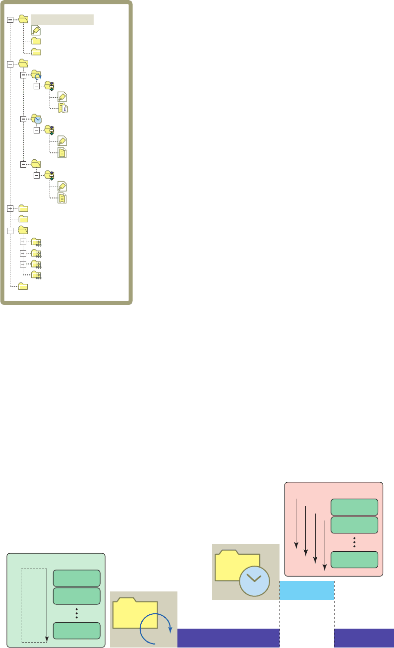
Tasks
Tasks are the rst level of scheduling within a project. A
task is a collection of scheduled programs. When a task
is executed, the associated programs are executed in the
order listed. This list of programs is known as the program
schedule. Tasks provide scheduling based on speci c con-
ditions and do not contain any executable code. Only one
task may be executing at any given time. The number of
tasks a controller can support depends on the speci c con-
troller. The main types of tasks ( Figure 15-7 ) include:
• Continuous tasks execute nonstop but are always
interrupted by a periodic task. Continuous tasks
have the lowest priority. A ControlLogix continuous
task is similar to the File 2 in the SLC 500 platform.
Here the continuous task is named Main Task.
• Periodic tasks function as timed interrupts. They
interrupt the continuous task and execute for a xed
length of time at speci c time intervals.
• Event tasks also function as interrupts. Rather than
being an interrupt on a timed basis, an event task
is triggered by an event that happened or failed to
happen.
Programs
Programs are the second level of scheduling within a
project. The function of the folders under Main Task is
to determine and specify the order in which the programs
Figure 15-6 Controller organizer tree.
Controller RSLogix
Tasks
Controller Tags
Program Tags
MainRoutine
Continuous
Program_01
Controller Fault Handler
Power-Up Handler
Program Tags
MainRoutine
Periodic
Unscheduled Programs
Data Types
Motion Groups
Trends
User-Defined
Program_02
Program Tags
Main
HMI
Strings
Predefined
Module-Defined
I/O Configuration
Figure 15-7 Continuous and periodic tasks.
Program 1
Program 2
Program 32
Continuous
task
Continuous task scan
Task auto-restart
Periodic task scan
5 ms
10 ms
15 ms
...
Program 1
Program 2
Program 32
Periodic
task
pet10882_ch15_317-372.indd 320pet10882_ch15_317-372.indd 320 7/27/10 6:42 PM7/27/10 6:42 PM
execute. There is no executable code within a program.
Routines within programs will execute in the order listed
below their associated task in the controller organizer as
shown in Figure 15-8 . In this example, according to the
listed order, the Main Program is scheduled to execute
rst, Program_A second, and Progam_B third. Programs
that are not assigned to a task are unscheduled. Unsched-
uled programs are downloaded to the controller but do
not execute. These programs remain unscheduled until
needed. Depending on the RSLogix 5000 software ver-
sion as many as 100 programs could be scheduled within
each task.
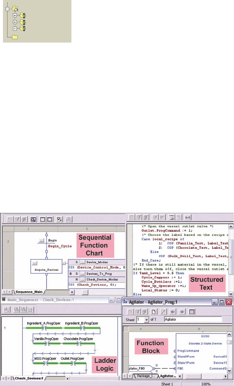
Routines
Routines are the third level of scheduling within a proj-
ect and provide the executable code for the project. Each
routine contains a set of logic elements for a speci c
programming language. When a routine is created it is
speci ed as ladder logic, sequential function chart, func-
tion block diagram or structured text ( Figure 15-9 ). Any
one routine must be completely in the same language.
The number of routines per project is limited only by the
amount of controller memory. Libraries of standard rou-
tines can be created that can be reused on multiple ma-
chines or applications. A routine can be assigned as one
of the following types:
• A main routine is one con gured to execute rst
when the program runs. Each program will have one
main routine typically followed by several or many
subroutines.
• A subroutine is one that is called by another routine.
Subroutines are used for large or complex program-
ming tasks or tasks that require more than one pro-
gramming language.
• A fault routine is one that executes if the controller
nds a program fault. Each program can have one
fault routine, if desired.
Tags
Unlike conventional controllers, ControlLogix uses a tag-
based addressing structure. Tags are meaningful names,
descriptive of your application and not merely generic
Figure 15-8 Order of execution of programs.
Main Task
Main Program
Program_A
Program_B
Unscheduled Programs
Figure 15-9 Each routine contains a set of logic elements for a specifi c programming language.
Memory and Project Organization Part 1 321
pet10882_ch15_317-372.indd 321pet10882_ch15_317-372.indd 321 7/27/10 6:43 PM7/27/10 6:43 PM
addresses. A tag is created to represent the data and iden-
tify areas in the controller’s memory where these data are
stored. In applications developed using Logix 5000 soft-
ware, there are no prede ned data tables such as in an
SLC500. When you want to use or monitor data in a pro-
gram you use tag names to refer to the memory locations,
as illustrated in Figure 15-10 . This functionality allows you
to name your data speci cally for their functions within the
control program while providing self-documented logic.
Whenever you wish to group data, you create an array,
which is a grouping of tags of similar types.
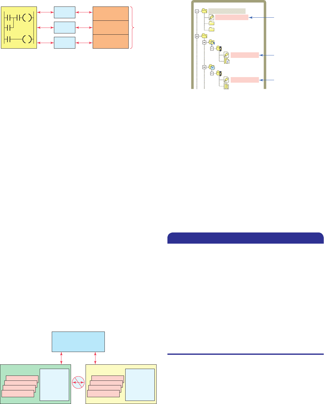
Scope refers to which programs have access to a tag.
The scope of a tag must be speci ed when you create the
tag. There are two scopes for tags: program scope and
controller scope. A program tag consists of data that can
be accessed only by routines within a speci c program
(local data). The routines in other programs cannot access
program scoped tags of another program. A controller tag
consists of data that are accessible by all routines within
a controller (global data). Figure 15-11 shows two pro-
grams, A and B, within a project. Note that each program
has program scope tags with identical names (Tag_1,
Tag_2, and Tag_3). Because they are program scoped,
there is no relationship between them, even though they
have the same name. The program scope data are acces-
sible only to the routines within a single program. The
same tag name may appear in different programs as local
variables because you can select the scope in which to
create the tag.
The scope of a tag must be declared when you cre-
ate the tag. Figure 15-12 shows program and controller
scoped tags as listed in the controller organizer under the
program they are assigned to. I/O tags are automatically
created as controller scoped tags.
There are four different tag types: base, alias, produced,
and consumed tags. The tag type de nes how the tag op-
erates within the project. A base tag stores various types
of data for use by logic in the project. This tag de nes a
memory location where data are stored. Base tag memory
use depends on the type of data the tag represents. An
example of the base tag Local:2:O.Data.4 is shown in
Figure15-13 and is based on the following format:
Location Network location
LOCAL 5 same chassis as the controller
Slot Slot number of I/O module in its chassis
Type Type of data
I 5 input
O 5 output
C 5 con guration
S 5 status
Member Speci c data from the I/O module; depends
on what type of data the module can store.
SubMember Speci c data related to a Member.
Bit Speci c point on a digital I/O module;
depends on the size of the I/O module
(0-31 for a 32-point module)
Figure 15-11 Program scoped and controller scoped tags.
Other routines
Main routine
Program
scoped tags
Tag_1
Tag_2
Tag_3
Program A
Program B
Program
scoped tags
Tag_1
Tag_2
Tag_3
Controller Scope Tags
Sensor_1
Temp_1
Other routines
Main routine
Figure 15-10 Tags used to assign memory locations.
Program Tags
Tag 1
Tag 2
Tag 3
Tag 1 Data
Tag 2 Data
Memory
locations
Tag 3 Data
Controller memory
Figure 15-12 Listing of program and controller scoped tags.
Controller
scoped
Controller RSLogix
Tasks
Controller Tags
Program Tags
MainRoutine
Continuous
Program_01
Controller Fault Handler
Power-Up Handler
Program Tags
MainRoutine
Periodic
Program_02
Program
scoped
Program
scoped
An alias tag is used to create an alternate name (alias)
for a tag. The alias tag is simply another name for an al-
ready named memory location. An alias tag can refer to
a base, alias, consumed, or produced tag. The alias tag is
often used to create a tag name to represent a real-word
input or output. Figure 15-14 shows an example of the
322 Part 1 Memory and Project Organization
pet10882_ch15_317-372.indd 322pet10882_ch15_317-372.indd 322 7/27/10 6:43 PM7/27/10 6:43 PM