Petruzella F.D. Programmable Logic Controllers
Подождите немного. Документ загружается.

• The Timer_Cooling.DN bit of the TOF timer
becomes true which energizes the Fan_Motor.
• After 10 s (10000 ms) have elapsed the Timer_Heat.
TT bit becomes false to turn off the Warning_Horn
and the Timer_Heat.DN bit becomes true to
energize the Heater_Contactor and turn on the
heating coils.
• When the Oven_Off_Button is momentarily actu-
ated the Oven_On_PL output goes false which turns
the pilot light off and opens the continuity of its
seal-in logic path.
• The Timer_Heat timer instruction and its DN
bit instruction become false which de-energizes
the Heater_Contactor and turns off the heating
coils.
• The Timer_Cooling timer begins accumulating time
and the fan continues to operate for the 5 minute
(300000 ms) delay period after which the Timer_
Cooling.DN bit becomes false to turn the fan off.
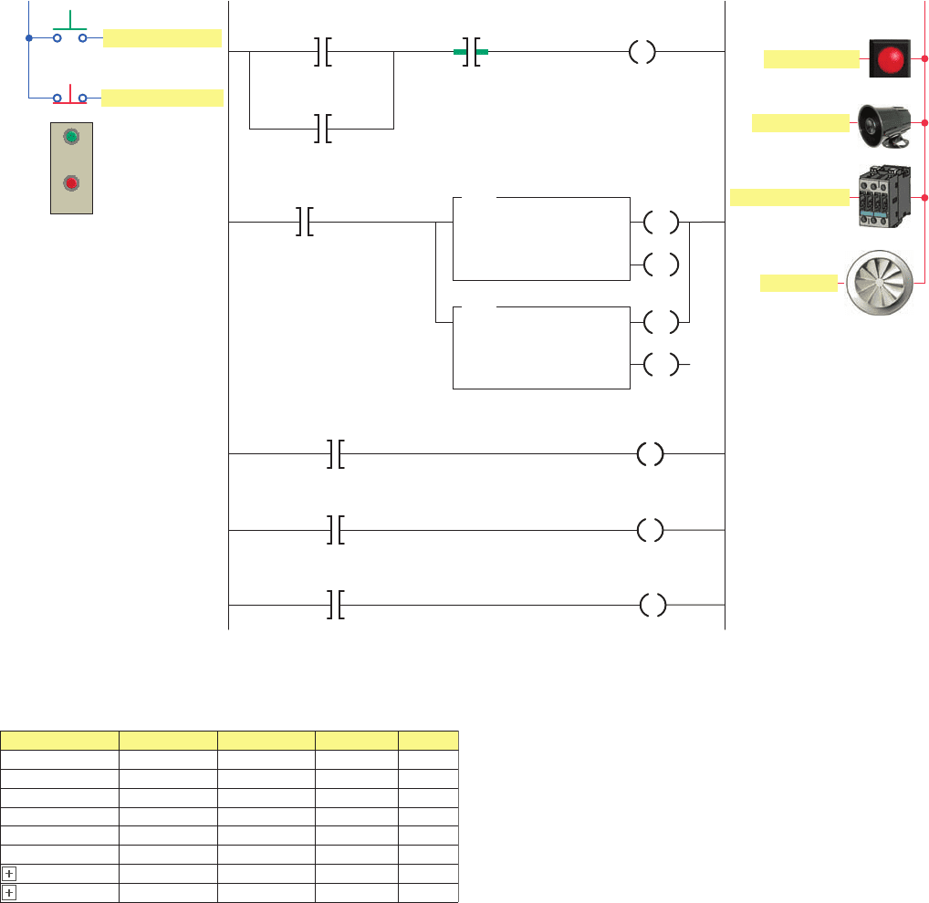
Figure 15-51 Timer control of a heating oven process.
L1
Inputs
Oven_On_PL
<Local:2:O.Data.2>
Oven_On_Bautton
Oven_Off_Button
Ladder logic program
Timer_Heat
10000←
0←
TON
TIMER ON DELAY
Timer
Preset
Accum
Warning_Horn
<Local:2:O.data.3>
Oven_On_PL
Timer_Heat.TT
Timer_Cooling
300000←
0←
TOF
TIMER OFF DELAY
Timer
Preset
Accum
EN
Heater_Contactor
<Local:2:O.data.4>
Warning_Horn
Timer_Heat.DN
Fan_Motor
<Local:2:O.data.5>
L2
Outputs
Heater_Contactor
Fan_Motor
Timer_Cooling.DN
Oven_On_PL
<Local:2:O.Data.2>
Oven_On_Button
<Local:1:I.Data.1>
Oven_Off_Button
<Local:1:I.Data.2>
Oven_On_PL
<Local:2:O.Data.2>
DN
DN
EN
ON
OFF
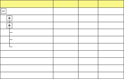
Figure 15-52 Tags created for heating oven process.
Tag Name
Warning_Horn
Heater_Contactor
Fan_Motor
Oven_On_PL
Oven_On_Button
Oven_Off_Button
Local:2:O.Data.3
Local:2:O.Data.4
Local:2:O.Data.5
Local:2:O.Data.2
Local:1:I.Data.1
Local:1:I.Data.2
Local:2:O.Data.3
Local:2:O.Data.4
Local:2:O.Data.5
Local:2:O.Data.2
Local:1:I.Data.1
Local:1:I.Data.2
BOOL
BOOL
BOOL
BOOL
BOOL
BOOL
Decimal
Decimal
Decimal
Decimal
Decimal
Decimal
TIMER
TIMER
-
Timer_Heat
-
Timer_Cooling
Alias For Base Tag Data Type Style
in Figure 15-52 . Operation of the program can be sum-
marized as follows:
• Pressing the Oven_On_Button energizes the Oven_
On_PL output which seals itself in and enables the
TON and TOF timer instructions.
• The Timer_Heat.TT bit of the TON timer becomes
true which sounds the Warning_Horn to warn that
the oven is about to come on.
Programming Timers Part 3 343
pet10882_ch15_317-372.indd 343pet10882_ch15_317-372.indd 343 7/27/10 6:43 PM7/27/10 6:43 PM

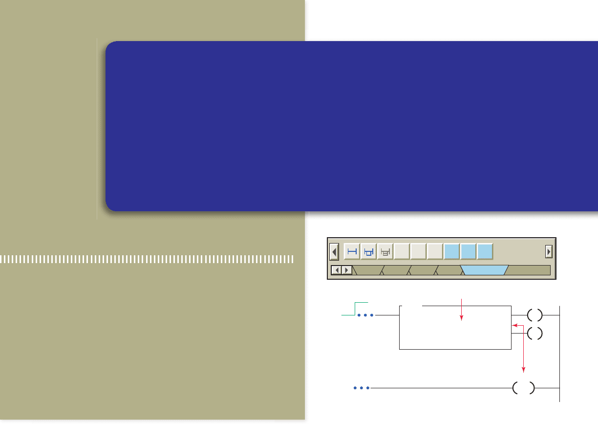
Retentive Timer On (RTO)
A retentive on-delay timer (RTO) operates the same
as a TON timer, except that the retentive timer retains
( remembers) its ACC value even if:
• The rung goes false.
• The processor is placed in the program mode.
• The processor faults.
• Power to the processor is temporarily interrupted
and the processor battery is functioning properly.
The ControlLogix RTO retentive on-delay timer in-
struction is shown in Figure 15-53 . The description of the
function block elds and tag references are the same as
for that of a TON timer; however, a RES reset instruction
must be used to reset the accumulated value of a retentive
timer. The RES instruction must have the same tag name
as the timer you want to reset.
An example application of a limit switch 2 minute
(120000 ms) RTO timer program is shown in Figure15-54 .
The different tags created to t the program are shown in
Figure 15-55 . The operation of the program can be sum-
marized as follows:
• The status and value of all instructions, with the
timer initially reset, are as shown in the monitor
tags window.
• When the Limit_Switch has been closed for 1min-
ute, the status and value of the instructions would be:
- PRE – 120000
- ACC – 60000
- LS_Timer.EN – 1
- LS_Timer.TT – 1
- LS_Timer.DN – 0
- LS_EN_PL – 1
- LS_TT_PL – 1
- LS_Alarm – 0
• When the Limit_Switch is opened after 1.5 minutes,
the status and value of the instructions would be:
- PRE – 120000
- ACC – 90000
- LS_Timer.EN – 0
- LS_Timer.TT – 0
- LS_Timer.DN – 0
- LS_EN_PL – 0
- LS_TT_PL – 0
- LS_Alarm – 0
Figure 15-53 RTO retentive on-delay timer instruction.
EN
DN
RES
SOL_On_Timer
Input side of rung
SOL_On_Timer
10000
0
RTO
RETENTIVE TIMER
ON
Timer
Preset
Accum
Figure 15-54 Limit switch RTO timer program.
Ladder logic program
Limit_Switch
<Local:1:I.Data.7>
LS_Timer
RT
O
RETENTIVE TIMER ON
Timer
Preset
Accum
120000
0
LS_EN_PL
<Local:2:O.Data.0>
LS_Timer.EN
LS_Timer
.TT
LS_Timer.DN
EN
DN
LS_TT_PL
<Local:2:O.Data.1>
LS_Alarm
<Local:2:O.Data.2>
Reset_LS_Timer
<Local:1:I.Data.2> LS_Timer
RES
OutputsInput
L2
L1
LS_EN_PL
Limit_Switch
Reset_LS_Timer
LS_TT_PL
Alarm
LS_Alarm
344 Part 3 Programming Timers
pet10882_ch15_317-372.indd 344pet10882_ch15_317-372.indd 344 7/27/10 6:43 PM7/27/10 6:43 PM
• When the Limit_Switch is closed and stays closed
until the timer times out, the status and value of the
instructions would be:
- PRE – 120000
- ACC –120000
- LS_Timer.EN – 1
- LS_Timer.TT – 0
- LS_Timer.DN – 1
- LS_EN_PL – 1
- LS_TT_PL – 0
- LS_Alarm – 1
• When the Limit_Switch is opened after the timer
times out, the status and value of the instructions
would be:
- PRE – 120000
- ACC –120000
- LS_Timer.EN – 0
- LS_Timer.TT – 0
- LS_Timer.DN – 1
- LS_EN_PL – 0
- LS_TT_PL – 0
- LS_Alarm – 1
• When the Reset_LS_Timer is closed, the status and
value of the instructions are reset to their original
values.
Figure 15-55 Tags created for the RTO retentive on-delay
timer program.
{…}
120000
0
0
0
0
DINT
DINT
BOOL
BOOL
BOOL
BOOL
TIMER
BOOL
Limit_Switch
LS_EN_PL
0
0
0
0
Decimal
Decimal
Decimal
Decimal
Decimal
Decimal
Decimal
Decimal
Decimal
BOOL
BOOL
LS_TT_PL
LS_Alarm
-
LS_Timer.PRE
-
LS_Timer.ACC
LS_Timer.EN
LS_Timer.TT
LS_Timer.DN
-
LS_Timer
Tag Name Value Style Data Type
Programming Timers Part 3 345
pet10882_ch15_317-372.indd 345pet10882_ch15_317-372.indd 345 7/27/10 6:43 PM7/27/10 6:43 PM
1. Compare the methods used to address timers in an
SLC 500 and a ControlLogix controller.
2. List the ve different members of a TIMER
structure.
3. What type of timing application may require you to
use a TON on-delay timer?
4. What PRE value is used for a timer?
5. To what value is the accumulated value of a timer
normally set?
6. What timer status bit is set to 1 when the TON
timer times out?
7. The TON instruction is self-resetting. Explain what
this means.
8. What number would be entered into the PRE value
of a ControlLogix timer for a timing period of
4.5minutes?
9. Compare the operation a TOF and a TON timer.
10. When does the rung of a TOF timer begin accumu-
lating time?
11. The RTO timer is a retentive timer. Explain what
this means.
12. How are the retentive timer and reset instruction
related?
PART 3 REVIEW QUESTIONS
1. Modify the original CLX ten-second TON timer pro-
gram with an additional rung added to the program
that will energize a solenoid whenever the timer is
enabled and timing. The solenoid is to be connected
to pin 6 of the digital output module.
2. With reference to the ladder logic of the CLX di-
verter gate program, assume the solenoid gate fails
to energize as programmed. You suspect the problem
is due to an open in the solenoid coil or wiring to it.
How might observation of the solenoid output status
light help con rm this?
3. You are required to extend the Green light-on
time of the CLX traf c control program to 40 sec-
onds. What changes would have to be made to the
program?
4. With reference to the CLX heating oven process
program, assume the oven-on pilot light burns out.
In what way would the operation of the program be
affected?
5. With reference to the CLX limit switch RTO pro-
gram, in addition to the alarm you are required to
install a warning pilot light to indicate that the timer
has timed out. How would you proceed?
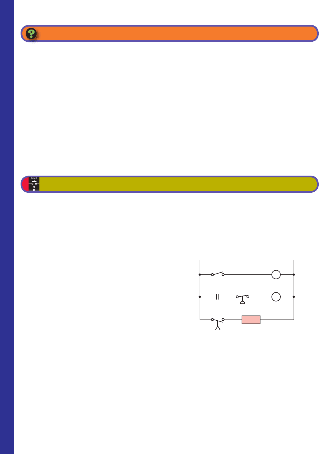
6. Implement the hardwired TON alarm circuit of
Figure 15-56 in Logix format.
PART 3 PROBLEMS
Figure 15-56 Hardwired TON alarm circuit for Problem 6.
L1
L2
CR
TR
10 s
ON/OFF
switch
Low pressure
switch
On-delay timer
TR
CR
Alarm
346 Part 3 Programming Timers
pet10882_ch15_317-372.indd 346pet10882_ch15_317-372.indd 346 7/27/10 6:43 PM7/27/10 6:43 PM
347
counter must be used to reset the accumulated value of
the counter to zero.
All counters are retentive in that the accumulated value
of any counter is retained, even during a power failure,
until reset. The on/off status of the counter done, over-
ow, and under ow bits are retentive as well. Control-
Logix counter parameters and status bits are shown in the
edit tags window of Figure 15-58 and can be summarized
as follows:
• Preset (PRE) Value —Speci es the value the
counter must reach before the done (DN) bit turns
on (1).
• Accumulated (ACC) Value —Is the number of
false-to-true transitions of the counter run. ACC is
reset to zero when a reset (RES) instruction (of the
same counter address) is executed.
• CU (Count-Up Enable Bit) —The count-up enable
bit indicates the CTU instruction is enabled.
Counters
Counters are similar to timers, except that a counter ac-
cumulates (counts) the changes in state of an external
trigger signal whereas timers increment using an internal
clock. PLC counters are generally triggered by a change
in an input eld device that causes a false-to-true transi-
tion of the counter ladder rung. It does not matter how
long the rung stays true or false—it is only the transition
that counts.
There are two basic counter types: count-up (CTU)
and count-down (CTD). The ControlLogix CTU in-
struction and counter selection toolbar are shown in
Figure15-57 . When you want to use a timer, you must
create a tag of type COUNTER (it is a prede ned data
type) and enter the preset and the accumulated value.
When entering the instruction, this tag must be de ned
before the preset and accumulated values can be entered.
A RES reset instruction that has the same tag name as the
Part Objectives
After completing this part, you will be able to:
• Understand ControlLogix counter tags and their
members
• Utilize status bits from counters in logic
• Develop ladder logic programs using ControlLogix
counters
Part 4 Programming
Counters
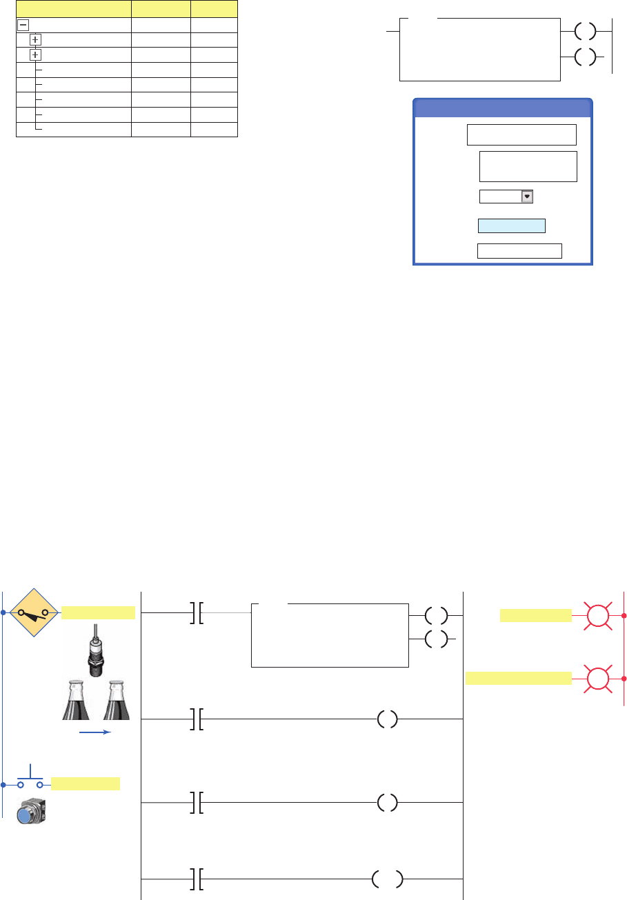
Figure 15-57 CTU count-up counter instruction.
CU
DN
Package_Counter
Input side of rung
False
True
RES
24←
0←
Tag name
CTU
Count Up
Counter P
ackage_Counter
Preset
Accum
TON
Favorites
TOF RTO CTU CTD RES
Add-On Alarms Bit Timer/Counter
pet10882_ch15_317-372.indd 347pet10882_ch15_317-372.indd 347 7/27/10 6:43 PM7/27/10 6:43 PM
348 Part 4 Programming Counters
• CD (Count-Down Enable Bit) —The count-down
enable bit indicates the CTD instruction is
enabled.
• DN (Count-Up Done Bit) —Is set (1) when ACC
value is equal to or greater than the PRE value. Is
reset by the RES instruction.
• OV (Over ow Bit) —The over ow bit indicates the
counter exceeded the upper limit. Is set when the
ACC value is greater than +2,147,483,647 and reset
when the reset instruction is executed. Note that the
accumulated value keeps incrementing even after
the ACC value equals the PRE value.
• UN (Under ow Bit) —Indicates that the counter
exceeded the lower limit of 22,147,483,648.
The counter tag name is declared using the new tag
properties dialog box shown in Figure 15-59 . Tag name,
description (optional), tag type, data type (base type is
used most often), and scope are selected or typed to com-
plete the validation.
Count-Up (CTU) Counter
Count-up (CTU) counters will cause the accumulated count
to increase by 1 every time there is a false-to-true transi-
tion of the counter ladder rung. An example application
of a count-up counter program used to count packets of
bottles is shown in Figure 15-60 . The operation of the
program can be summarized as follows:
• Each open-to-close transition of the Bottle_Sensor
proximity switch causes the counter to increment by 1.
Figure 15-58 ControlLogix counter parameters and
status bits.
DINT
DINT
BOOL
BOOL
BOOL
BOOL
COUNTER
BOOL
Part_Counter.OV
Part_Counter.UN
Decimal
Decimal
Decimal
Decimal
Decimal
Decimal
Decimal
Decimal
-
Part_Counter.PRE
-
Part_Counter.ACC
Part_Counter.CU
Part_Counter.CD
Part_Counter.DN
-
Part_Counter
Tag Name Data Type Style
Figure 15-59 Counter tag validation.
Main programScope
COUNTERData Type
BaseTag Type
24 bottle counterDescription
Package_CounterName
CV
DN
Package_Counter
24←
0←
CTU
Count Up
Counter
Preset
Accum
New Tag
24 bottle counter
Figure 15-60 Count-up counter program used to count packets of bottles.
Ladder logic program
24 bottle counter
Bottle_Sensor
<Local:1:I.Data.1>
Increment_PL
<Local:2:O.Data.4>
24 bottle counter
P
ackage_Counter.CU
24 bottle counter
Package_Counter.DN
CU
DN
Preset_Reached_PL
<Local:2:O.Data.5>
Reset_Button
<Local:1:I.Data.3>
24 bottle counter
Package_Counter
OutputsInputs
L2
L1
Increment_PL
Bottle_Sensor
Reset_Button
Preset_Reached_PL
CTU
Count Up
Counter
Preset
Accum
Package_Counter
24
*
0
*
RES
pet10882_ch15_317-372.indd 348pet10882_ch15_317-372.indd 348 7/27/10 6:43 PM7/27/10 6:43 PM
• The Increment_PL controlled by the Package_
Counter.CU status bit turns on and off as
each bottle passes to show that the counter is
incrementing.
• When the accumulated value of the counter is 24
the DN bit of the counter is set and switches on the
Preset_Reached_PL.
• The counter is reset by momentarily closing the
Reset_Button.
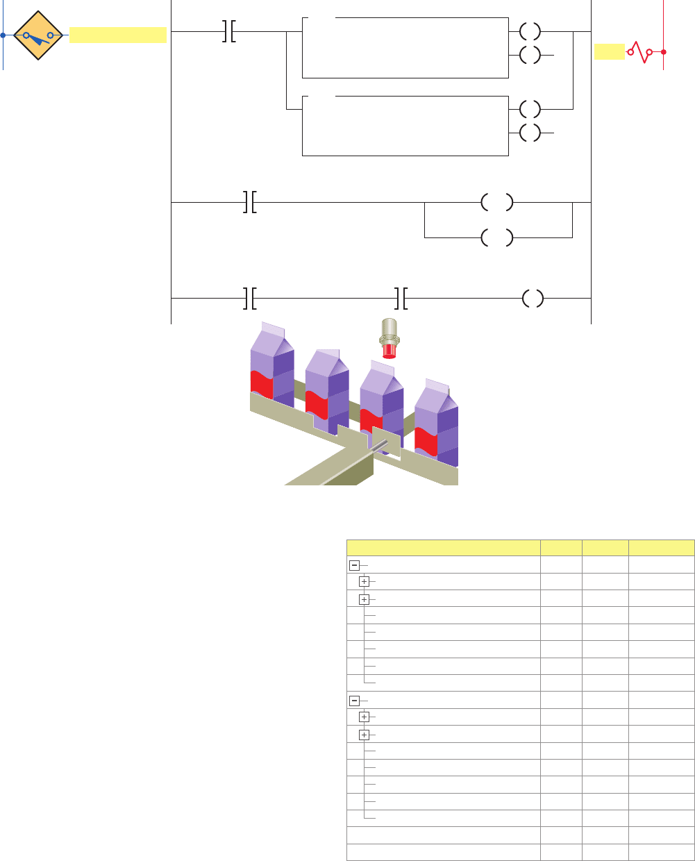
The program shown in Figure 15-61 uses two CTU in-
structions as part of a program to remove 5 out of every
10 containers from a conveyor line using an electric so-
lenoid. The different tags created to t the program are
shown in Figure 15-62 . The operation of the program can
be summarized as follows:
• The preset for the Container_Counter_Counts is set
for 6 and that for the Container_Counter_Max is
setto 11.
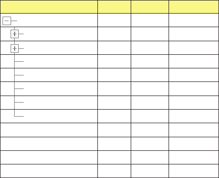
Figure 15-62 Tags created for the CTU program used to
remove containers from a conveyor line.
Container_Counter_Counts .CU
Container_Counter_Counts .CD
Container_Counter_Counts .DN
Container_Counter_Counts .OV
Container_Counter_Counts .UN
Container_Counter_Counts
Container_Counter_Counts .PRE
Container_Counter_Counts .ACC
0
0
0
0
0
{...}
6
0
Decimal
Decimal
Decimal
Decimal
Decimal
Decimal
Decimal
BOOL
BOOL
BOOL
BOOL
BOOL
COUNTER
DINT
DINT
Container_Counter_Max .CU
Container_Counter_Max .CD
Container_Counter_Max .DN
Container_Counter_Max .OV
Container_Counter_Max .UN
Container_Counter_Max
Container_Counter_Max .PRE
Container_Counter_Max .ACC
0
0
0
0
0
{...}
11
0
Decimal
Decimal
Decimal
Decimal
Decimal
Decimal
Decimal
BOOL
BOOL
BOOL
BOOL
BOOL
0 Decimal BOOL
0
Container_Sensor
SOL Decimal BOOL
COUNTER
DINT
DINT
Tag Name Value Style Data Type
Figure 15-61 CTU program used to remove containers from a conveyor line.
L1 L2
Input
Container_Sensor
<Local:1:I.Data.2>
Container_Sensor
<Local:1:I.Data.2>
SOL
<Local:2:O.Data.2>
Container_Counter_Max.DN
Container_Counter_Counts
Container_Counter_Max
Container_Counter_Counts
.DN
Ladder logic program
CTU
Count Up
Counter
Preset
Accum
Container_Counter_Counts
6←
0←
Output
Sensor
Solenoid
SOL
Container_Sensor
CU
DN
CTU
Count Up
Counter
Preset
Accum
Container_Counter_Max
11←
0←
CU
DN
RES
RES
Programming Counters Part 4 349
pet10882_ch15_317-372.indd 349pet10882_ch15_317-372.indd 349 7/27/10 6:43 PM7/27/10 6:43 PM
• When the container is detected both counters will
increase their accumulated values by 1.
• When the sixth part arrives the Container_Counter_
Counts counter will then be done, thereby allow-
ing the solenoid to actuate for any container after
the fth.
• The Container_Counter_Max counter will continue
until the eleventh part is detected and then both of
the counters will be reset.
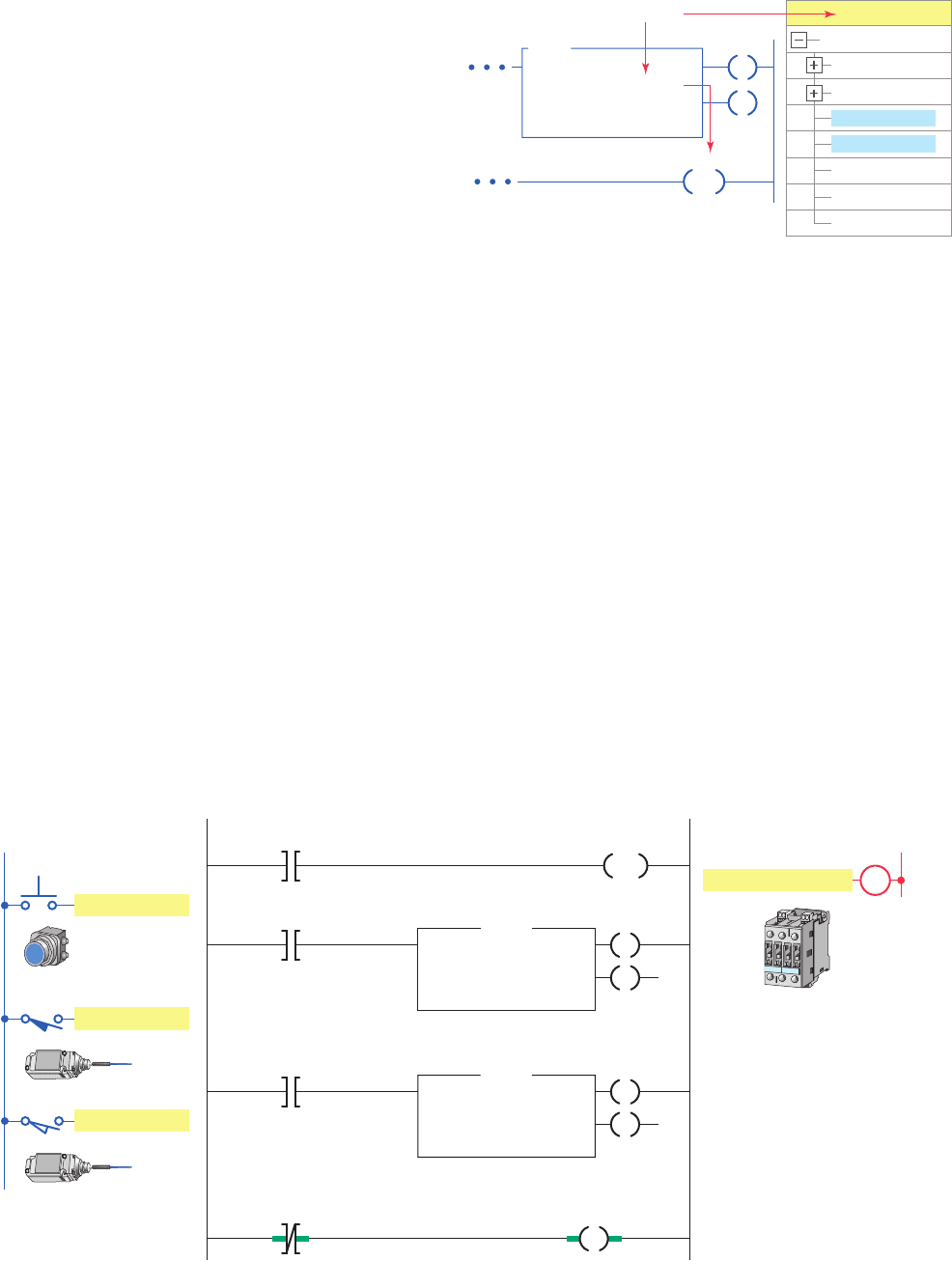
Count-Down (CTD) Counter
The count-down (CTD) counter operates in a fashion op-
posite to the count-up CTU counter. CTD counters will
cause the accumulated count to decrease instead of in-
crease by one every time there is a false-to-true transi-
tion of the counter ladder rung. The ControlLogix CTD
down-counter instruction is shown in Figure 15-63 . The
descriptions of the function block elds and the tag ref-
erences are the same as those associated with the CTU
function block. The CTD instruction is typically used
with a CTU instruction that references the same counter
structure.
The application program shown in Figure 15-64 is
used to limit the number of parts that can be stored in
the buffer zone to a maximum of 50. A CTU counter
and a CTD counter are used together with the same
Figure 15-63 Count-down CTD counter instruction.
Counter_1.CU
Counter_1.CD
Counter_1.DN
Counter_1.OV
Counter_1.UN
Counter_1
Counter_1.PRE
Counter_1.ACC
Tag Name
Count Down
Counter
Preset
Accum
CTD
Counter_1
T
ag name
Input
side of
rung
Counter_1
CD
DN
RES
Figure 15-64 CTU counter and CTD counter used together to form an Up/Down counter.
Restart_Button
<Local:1:I.Data.1>
Counter_1
Ladder logic prog
ram
CTU
Restart_Button
Count Up
Counter Counter_1
Preset
Accum
50←
0←
CU
DN
Enter_Limit_Sw
<Local:1:I.Data.3>
CTD
Count Up
Counter Counter_1
Preset
Accum
50←
0←
CD
DN
Enter_Limit_Sw
<Local:1:I.Data.4>
Counter_1.DN
Conveyor_Contactor
<Local:2:O.Data.2>
RES
L1
Inputs
L2
Output
C
Enter_Limit_Sw
Exit_Limit_Sw
Conveyor_Contactor
address to form an Up/Down counter. This is the most
common type of application of the CTD counter. The
different tags created to t the program are shown in
Figure15-65 . The operation of the program can be sum-
marized as follows:
• The Restart_Button is momentarily actuated at any
time to reset the accumulated value of the counter
tozero.
• Conveyor brings parts into a buffer zone.
• Each time a part enters the buffer zone, the
Enter_Limit_Sw is actuated and Counter_1
increments by 1.
350 Part 4 Programming Counters
pet10882_ch15_317-372.indd 350pet10882_ch15_317-372.indd 350 7/27/10 6:43 PM7/27/10 6:43 PM
• Each time a part leaves the buffer zone, the
Exit_Limit_Sw is actuated and Counter_1
decrements by 1.
• When the number of parts in the buffer zone, at
anyone time, reaches 50, the Counter_1.DN bit
isset.
• As a result the Conveyor_Contactor rung goes
false to de-energize the conveyor contactor, auto-
matically stopping the conveyor from bringing in
any more parts until the accumulated count drops
below 50.
Figure 15-65 Tags created for the Up/Down counter
program.
Counter_1.CU
Counter_1.CD
Counter_1.DN
Counter_1.OV
Counter_1.UN
Counter_1
Counter_1.PRE
Counter_1.ACC
0
0
0
0
0
0
{ . . . }
50
0
Decimal
Decimal
Decimal
Decimal
Decimal
Decimal
Decimal
Decimal
BOOL
BOOL
BOOL
BOOL
BOOL
COUNTER
DINT
DINT
Conveyor_Contactor
Restart_Button
Enter_Limit_Sw
Exit_Limit_Sw
1
0
0
Decimal
Decimal
Decimal
BOOL
BOOL
BOOL
BOOL
Tag Name Value Style Data Type
Programming Counters Part 4 351
pet10882_ch15_317-372.indd 351pet10882_ch15_317-372.indd 351 7/27/10 6:43 PM7/27/10 6:43 PM

1. In what way are timers and counters similar?
2. Outline the procedure followed to create a tag when
you want to use a counter.
3. All counters are retentive. In what way does this af-
fect their operation?
4. What is speci ed by the preset value of a counter?
5. When is each of the following counter bits set?
a. C U
b. D N
c. C D
6. Compare the operations of a CTU and a CTD
counter.
7. What is an Up/Down counter?
8. Explain how you go about creating tags for an Up/
Down counter that uses a CTU and CTD instruction.
PART 4 REVIEW QUESTIONS
1. With reference to the CTU packets of bottles pro-
gram, what changes to the program would be re-
quired to count 6 bottle packets?
2. With reference to the CTU program used to remove
containers from a conveyor line, assume the output
solenoid coil failed open. In what way would the
operation of the program be affected?
3. Modify the original Up/Down counter program to
include:
a. A red pilot light to indicate entry of a part into the
buffer zone. Light to be connected to pin 4 of the
digital output module.
b. A green pilot light to indicate exit of a part from
the buffer zone. Light to be connected to pin 3 of
the digital output module.
4. Write a ControlLogix program, complete with tags,
for an Up/Down counter used to keep track of cars
entering and exiting a parking lot. The program re-
quirements for this application can be summarized
as follows:
• The parking lot holds 30 vehicles.
• There is an entrance vehicle sensor and an exit
vehicle sensor.
• When the parking lot is full a Lot Full sign is
illuminated.
• Whenever a car exits the lot, a Caution Buzzer/
Light is activated to warn pedestrians.
PART 4 PROBLEMS
352 Part 4 Programming Counters
pet10882_ch15_317-372.indd 352pet10882_ch15_317-372.indd 352 7/27/10 6:43 PM7/27/10 6:43 PM