Petruzella F.D. Programmable Logic Controllers
Подождите немного. Документ загружается.


With text-based Logix systems you can use the name
of the tag to document your ladder code and organize
your data to mirror your application. For the programmed
motor start/stop control circuit three tags Motor_Start,
Motor_Stop, and Motor_Run are created. Figure 15-33
illustrates how the Motor_Start tag is created in the New
Tag window. This window can be accessed by right
clicking the ? mark above the XIC instruction in the lad-
der logic program. Since this tag represents a value from
an input eld device a link through the module to the
eld device must be created. When Local:1:I.Data is se-
lected a dialog box for all of the terminal numbers on the
input module appears. The tag name (Motor_Start) used
in the program is then linked to input terminal number3
where the eld device represented by the tag name is
connected.
Figure 15-34 shows what the ladder logic program
would look like after all three tags have been created.
Users have the ability to reference data via multiple names
using Aliases. This allows the exibility to name data dif-
ferently depending on their use. The tag description pro-
vides for a more meaningful description of the tag name.
Tag names are downloaded and stored in the controller
but the description is not as it is part of the documentation
of the project.
Figure 15-35 shows the state of the tags created for
the motor start/stop program as seen in the program and
Figure 15-33 Creating the Motor_Start tag.
New Tag
Alias
Local:1:I.Data
Motor_StartName:
Start button for
motor
Description:
Name
Local:1:C
Local:1:I
Local:1:I.Fault
Local:1:I.Data
DINT
AB:1756_DO:C:0
AB:1756_DO:I:0
Data T
ype
+
–
0
8
16
24
1
9
17
25
2
10
18
26
3
11
19
27
5
13
21
29
6
14
22
30
7
15
23
31
4
12
20
28
Figure 15-34 Ladder logic program after all tags have been created.
Motor contactor coil
Motor_Run
<Local:2:O.Data.4>
Motor contactor coil
Motor_Run
<Local:2:O.Data.4>
Stop button for
motor
Motor_Stop
<Local:1:I.Data.4>
Start button for
motor
Motor_Star
t
<Local:1:I.Data.3>
Description
Tag Name
Alias
Figure 15-35 Ladder logic program and Monitor Tags window with motor operating.
Motor contactor coil
Motor_Run
<Local:2:O.Data.4>
Motor contactor coil
Motor_Run
<Local:2:O.Data.4>
Stop button for
motor
Motor_Stop
<Local:1:I.Data.4>
Ladder logic programInputs Output
Contactor
Start button for
motor
Motor_Start
<Local:1:I.Data.3>
Stop
Start
Monitor Tags Window
Tag Name Value Style Data Type
Motor_Start 0 Decimal BOOL
Description
Start button for motor
Motor_Stop 1 Decimal BOOL Stop button for motor
Motor_Run 1 Decimal BOOL Motor contactor coil
M
L2
L1
Motor_Stop
Motor_Start
Motor_Run
Bit-Level Programming Part 2 333
pet10882_ch15_317-372.indd 333pet10882_ch15_317-372.indd 333 7/27/10 6:43 PM7/27/10 6:43 PM
an equivalent hardwired control circuit. The operation of
the program can be summarized as follows:
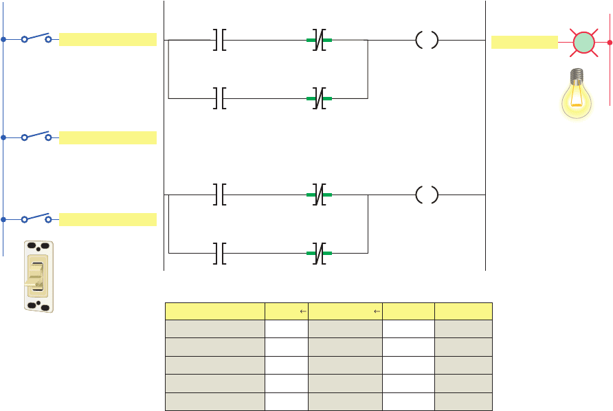
• An internal relay is used to execute the logic of
the circuit without having to use a real-world
output.
• The status value stored in memory for all tags, when
all input switches are open, is 0 and so the room
light will be off.
• Closing Position_1_Switch changes the status of its
XIC instruction from false to true thereby establish-
ing logic continuity for Rung 1.
• As a result, the status of the internal relay coil and
its XIC contact change from false to true.
• This establishes logic continuity for Rung 2 and
switches the room light on.
• A change in the state of any of input switches will
change the current state of the light.
Latch and Unlatch Instructions
The output latch (OTL) instruction is a retentive output
instruction that is used to maintain, or latch, an output. If
this output is turned on, it will stay on even if the status
Monitor Tags window, when the motor is operating. When
the motor is operating:
• The XIC Motor_Start instruction is false because
the NO start button is open; therefore its value is 0.
• The XIC Motor_Stop instruction is true because the
NC stop button is closed; therefore its value is 1.
• The OTE Motor_Run instruction is true because the
rung has logic continuity; therefore its value is 1.
Internal Relay Instructions
Internal relay instructions are used when other than real-
world eld devices are needed as input or output reference
instructions. For example, an internal relay bit is used as
an output when the logical resultant of a rung is used to
control other internal logic. An internal control relay is
programmed in the ControlLogix system by creating a tag
(either program or controller type) and assigning a Boolean
type to the tag.
Figure 15-36 shows a ControlLogix program that uses
an internal relay to implement on/off control of a room
light from three different entrances or positions. Three
single pole switches are used for inputs in place of the
two 3-way and one 4-way switches normally required for
Figure 15-36 Internal relay to implement on/off control of a room light from three different entrances.
Name Value Force Mask
Monitor Tags Window
Style Data Type
Internal_Relay 0 Decimal BOOL
Position_1_Sw... 0 Decimal BOOL
Position_2_Sw... 0 Decimal
Decimal
BOOL
0 BOOLPosition_3_Sw...
Decimal0 BOOLRoom_Light
Ladder logic program
Position_1_Switch
<Local:1:I.Data.1>
L
Position_2_Switch
<Local:1:I.Data.2>
Internal_Relay
Position_2_Switch
<Local:1:I.Data.2>
Position_1_Switch
<Local:1:I.Data.1>
Internal_Relay
Position_3_Switch
<Local:1:I.Data.3>
Room_Light
<Local:2:O.Data.5>
Position_3_Switch
<Local:1:I.Data.3>
Internal_Relay
OutputInputs
L2
L1
Room_Light
Position_1_Switch
Position_2_Switch
Position_3_Switch
334 Part 2 Bit-Level Programming
pet10882_ch15_317-372.indd 334pet10882_ch15_317-372.indd 334 7/27/10 6:43 PM7/27/10 6:43 PM
of the input logic that caused the output to energize be-
comes false. The OTL instruction will remain in a latched
on condition until an unlatch instruction (OTU) with the
same referenced tag is energized. The OTL instruction is
often used in programs where the value of a variable must
be maintained in instances where there is a shutdown due
to a power failure or system fault. Retentive memory per-
mits the system to be restarted with memory locations
holding the values that were present when the program
execution was halted.
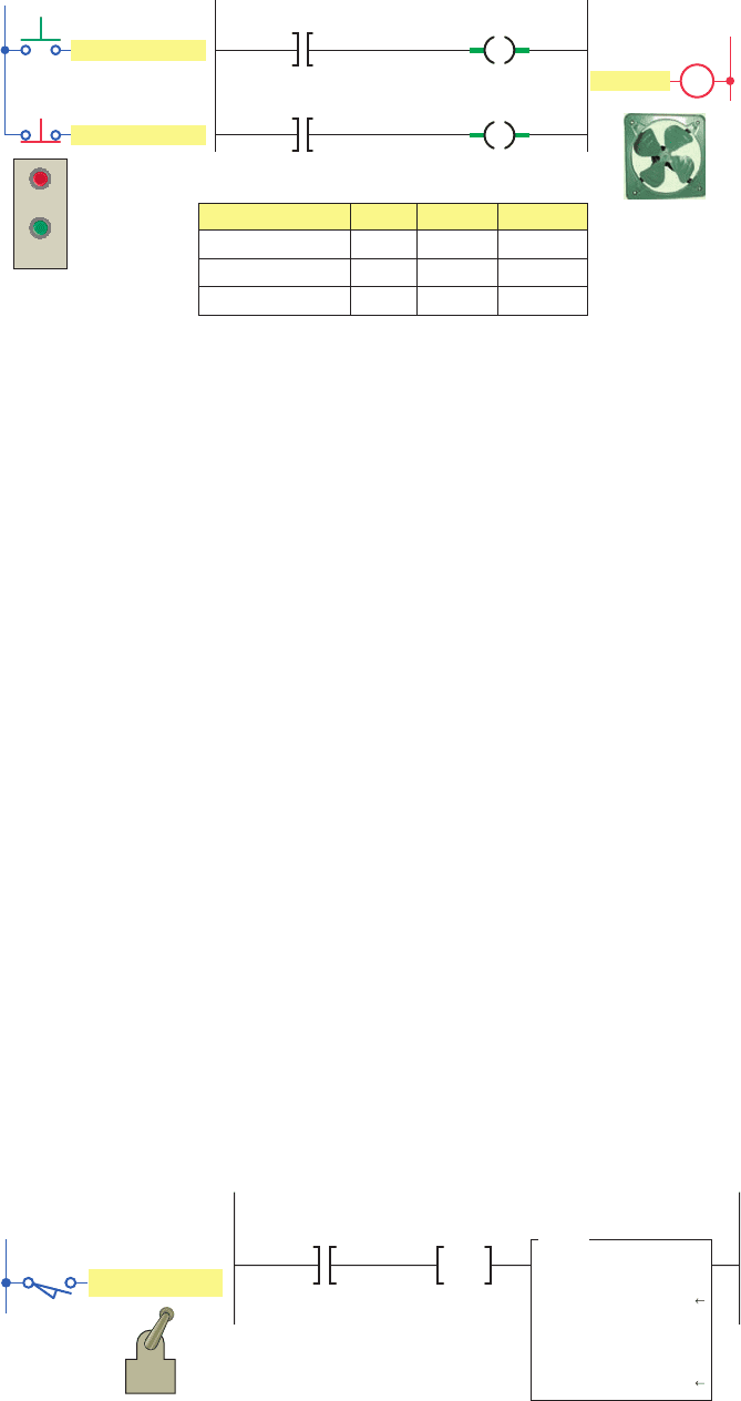
Figure 15-37 shows a ControlLogix program that uses
an output latch and unlatch instruction pair to implement
the control of a vent fan motor. The operation of the pro-
gram can be summarized as follows:
• The OTL instruction will write a 1 to its address
when true.
• When the OTL goes false, the output address will
remain a 1.
• This is true even if the processor powers down and
then back up.
• The output address will remain a 1 until reset to 0
by the unlatch instruction.
• If the output address is off, both the latch and un-
latch instructions are not intensi ed, but once the bit
is turned on, you will see both the latch and unlatch
intensi ed even though both inputs are shut off.
One-Shot Instruction
The CLX One-Shot (ONS) instruction is an input instruc-
tion used to turn an output on for one program scan only.
The program of Figure 15-38 uses the ONS instruction
with a math instruction to perform a calculation once per
scan. This program is used to execute the ADD math func-
tion only once per actuation of the limit switch, no matter
how long the limit switch is held closed. The operation of
the program can be summarized as follows:
• On any scan for which limit_switch_1 is cleared or
storage_1 is set, this rung has no effect.
• On any scan for which limit_switch_1 is set and stor-
age_1 is cleared, the ONS instruction sets storage_1
and the ADD instruction increments sum by 1.
• As long as limit_switch_1 stays set, sum stays
the same value. The limit_switch_1 must go from
cleared to set again for sum to be incremented again.
Figure 15-37 Output latch and unlatch instructions used to control a vent
fanmotor.
Vent_Fan
<Local:2:O.Data.4>
Fan_OFF_Button
<Local:1:I.Data.3>
Ladder logic programInputs
Output
Vent_Fan
<Local:2:O.Data.4>
L
U
Fan_ON_Button
<Local:1:I.Data.2>
ON
OFF
Monitor Tags Window
Tag Name Value Style Data Type
Fan_ON_Button 0 Decimal BOOL
Fan_OFF_Button 0 Decimal BOOL
Vent_Fan 1 Decimal BOOL
M
L2
L1
Fan_ON_Button
Fan_OFF_Button
Vent_Fan
Figure 15-38 ONS instruction used to perform a calculation once per scan.
Ladder logic programInput
L1
Limit_Switch_1
Limit_Switch_1
<Local:1:I.Data.6>
Storage_1
ONS
ADD
Add
Source A
Source B
Sum
0
1
Dest Sum
0
Bit-Level Programming Part 2 335
pet10882_ch15_317-372.indd 335pet10882_ch15_317-372.indd 335 7/27/10 6:43 PM7/27/10 6:43 PM

1. What operations are performed by the processor
during the program scan?
2. With a ControlLogix processor I/O updates occur
asynchronously. Explain what this means.
3. In ladder logic programming into what two broad
categories can instruction types be classi ed?
4. A eld input switch is examined using an XIC
instruction.
a. What is the value (0 or 1) stored in its memory
bit when the switch is opened and closed?
b. What is the state of the instruction (true or false)
when the switch is opened and closed?
5. A eld input switch is examined using an XIO
instruction.
a. What is the value (0 or 1) stored in its memory
bit when the switch is opened and closed?
b. What is the state of the instruction (true or false)
when the switch is opened and closed?
6. The value of an OTE instruction as it appears in
the Monitor Tags window is 1. Explain what this
means as far as the status of a real-world eld out-
put and programmed XIC and XIO instructions
associated with this tag are concerned.
7. D e ne a tag in the ControlLogix system.
8. What advantage do tag-based addressing systems
have over rack/slot and rack/group types?
9. How is an internal relay programmed in the
ControlLogix system?
10. The output latch instruction is a retentive output
instruction. Explain what retentive means.
11. The ControlLogix ONS instruction is a one-shot
instruction. Explain what this means.
PART 2 REVIEW QUESTIONS
1. Modify the original ControlLogix start/stop motor
control program with a second start and stop button
added to the program. The additional start button is
to be connected to pin 1 and the stop button to pin 2
of the digital input module.
2. Extend control of the original ControlLogix inter-
nal relay program used to control a room light from
3 entrances to 4. The additional single-pole switch
is to be connected to pin 4 of the digital input
module.
3. Implement the hardwired latching relay alarm circuit
of Figure 15-39 in Logix format. The alarm will be
latched on anytime:
• The normally open temperature switch closes.
• Both normally open oat switches 1 and
2 close.
• Either normally open sensor switch 1 or 2 closes
while the normally closed pressure switch is closed.
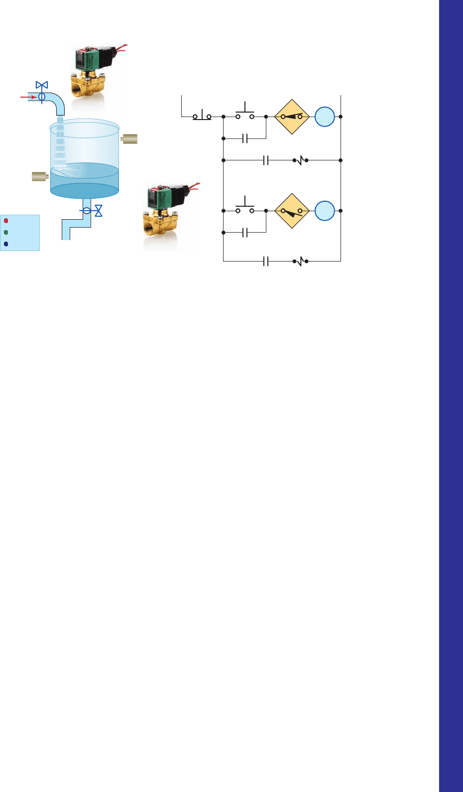
4. Implement the hardwired tank lling and emptying
operation shown in Figure 15-40 in Logix format.
PART 2 PROBLEMS
Figure 15-39 Hardwired latching relay alarm circuit
forProblem 3.
Relay
contact
Latch
coil
120 VAC
Reset button
24 VDC
Temp Sw
Float Sw 1
Sensor Sw 1
Sensor Sw 2
Float Sw 2
Pressure
Sw
Alarm
L
Unlatch
coil
U
336 Part 2 Bit-Level Programming
pet10882_ch15_317-372.indd 336pet10882_ch15_317-372.indd 336 7/27/10 6:43 PM7/27/10 6:43 PM
Solenoid B
Stop
Fill
1CR
1
2CR
1
2CR
2
1CR
2
Full tank
sensor
Empty tank
sensor
L1 L2
Empty
1CR
2CR
Solenoid A
Full tank
sensor
Empty tank
sensor
Control panel
Stop
Fill
Empty
Solenoid B
Solenoid A
Figure 15-40 Hardwired tank fi lling and emptying operation for Problem 4.
Source: Photo courtesy ASCO Valve Inc., www.ascovalve.com.
• Anytime the liquid level of the tank is above
the empty-level mark, momentarily pressing
theEMPTY pushbutton will energize control
relay2CR.
• Contacts 2CR
1
and 2CR
2
will both close to seal
in the 2CR coil and energize normally closed
solenoid valve B to start emptying the tank.
• When the liquid reaches the empty level, the
normally open empty-level sensor switch opens to
open the circuit to the 2CR relay coil and switch
solenoid valve B to its de-energized closed state.
• The stop button may be pressed at any time to halt
the process.
The operation of the control circuit can be summa-
rized as follows:
• Assuming the liquid level of the tank is at or below
the empty level mark, momentarily pressing the
FILL pushbutton will energize control relay 1CR.
• Contacts 1CR
1
and 1CR
2
will both close to seal
in the 1CR coil and energize normally closed
solenoid valve A to start lling the tank.
• As the tank lls, the normally open empty-level
sensor switch closes.
• When the liquid reaches the full level, the normally
closed full-level sensor switch opens to open the
circuit to the 1CR relay coil and switch solenoid
valve A to its de-energized closed state.
Bit-Level Programming Part 2 337
pet10882_ch15_317-372.indd 337pet10882_ch15_317-372.indd 337 7/27/10 6:43 PM7/27/10 6:43 PM

338
number (DINT). The time base is always 1 msec.
For example, for a 3 second timer, enter 3000 for
the PRE value.
• Accumulator (ACC) —The accumulator value is
the number of milliseconds the instruction has been
enabled. The accumulator value stops changing
when ACC value 5 PRE value.
• Enable Bit (EN) —The enable bit indicates the
TON instruction is enabled. The EN bit is true when
the rung input logic is true, and false when the rung
input logic is false.
• Timer Timing Bit (TT) —The timing bit indicates
that a timing operation is in process. The TT bit is
true only when the accumulator is incrementing.
TT remains true until the accumulator reaches the
preset value.
• Done Bit (DN) —The done bit indicates that ac-
cumulated value (ACC) is equal to the preset (PRE)
Timer Predefi ned Structure
Timers are used to turn outputs on and off after a time
delay, turn outputs on or off for a set amount of time, and
keep track of the time an output is on or off. The timer
address in the SLC 500 controller is a data table address
or symbol, whereas the timer address in the ControlLogix
controller is a prede ned structure of the TIMER data
type. The TIMER structure is shown in Figure 15-41 .
Timer parameters and status bits include:
• Tag Name —User-friendly tag name for the timer
(e.g., Pump_Timer). If you want to use a timer, you
must create a tag of type timer.
• Preset (PRE) —The number of time increments that
the timer must accumulate to reach the desired time
delay. Speci es the value (in milliseconds) which
the timer must reach before the done bit (DN)
changes state. The preset value is stored as a binary
Part Objectives
After completing this part, you will be able to:
• Understand ControlLogix timer tags and their members
• Utilize status bits from timers in logic
• Develop ladder logic programs using ControlLogix
timers
Part 3 Programming Timers
Figure 15-41 TIMER predefi ned structure.
Data Type: TIMER
Name
Members: Data Type Size: 12 byte(s)
Data Type Style Description
PRE
ACC
EN
TT
DN
DINT Decimal
DINT
BOOL
BOOL
BOOL
Decimal
Decimal
Decimal
Decimal
Name:
Description:
Pump_Timer
pet10882_ch15_317-372.indd 338pet10882_ch15_317-372.indd 338 7/27/10 6:43 PM7/27/10 6:43 PM
value. The DN bit signals the end of the timing pro-
cess by changing states from false-to-true or from
true-to-false depending on the type of time contact
instruction used. The DN bit is the most commonly
used timer status bit.
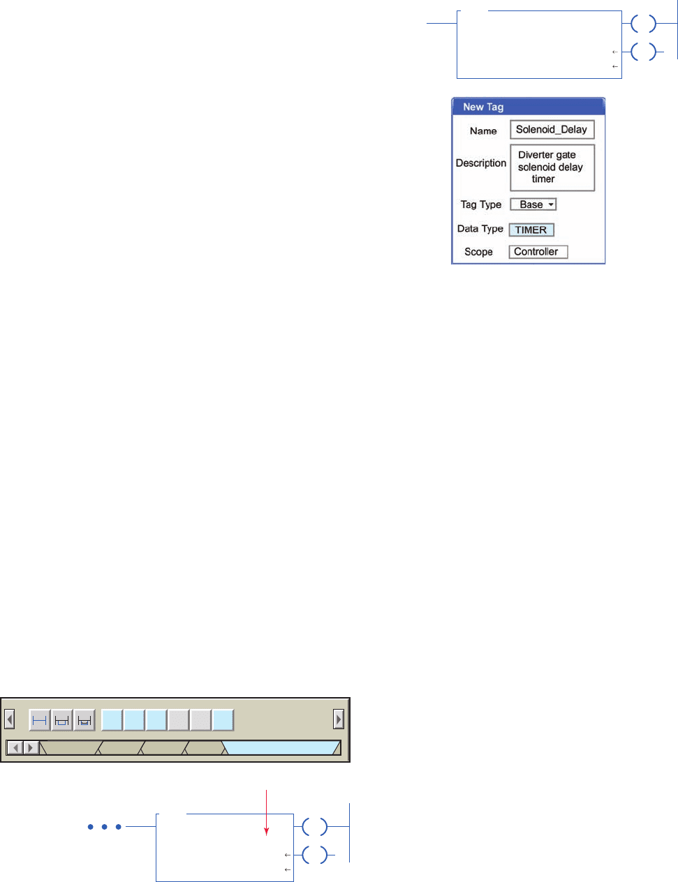
On-Delay Timer (TON)
The on-delay timer (TON) is a nonretentive output in-
struction used when the application requires an action to
occur at some time after the rung conditions for the timer
become true. The ControlLogix TON on-delay instruction
and timer selection toolbar are shown in Figure 15-42 .
When you want to use a timer, you must create a tag of
type TIMER (it is a prede ned data type) and enter the
preset and the accumulated value. The tag must be de ned
before the preset and accumulated values can be entered.
A value can be entered for the accumulator while pro-
gramming. When the program is downloaded this value
will be in the timer for the rst scan. If the TON timer is
not enabled the value will be set back to zero. Normally
zero will be entered for the accumulator value.
The timer tag name is declared using the new tag prop-
erties dialog box shown in Figure 15-43 . Tag name, de-
scription (optional), tag type, data type, and scope are
selected or typed to complete the validation. A descriptive
tag name, such as Solenoid_Delay, makes it easier to know
what function the timer serves in the control system.
The program of Figure 15-44 is an example of a 10000ms
(10 s) TON timer. Timers generate both word level (DINT)
and bit level (BOOL) data and status. The operation of the
program can be summarized with reference to the Moni-
tor Tags window.
• The status of all instruction is shown after the timer
input switch has been switched from off to on (1)
and accumulated 5000 ms (5 s) of time.
• At this halfway point the EN bit is 1 since the rung
is true, the TT bit is 1 since the accumulated value is
changing, and the DN bit is 0 since the accumulated
value does not yet equal the preset value.
• When the ACC equals PRE, the accumulated value
stops incrementing, EN stays on for as long as the
rung remains true, TT equals 0 since the accumu-
lated value is not changing, and DN equals 1 since
ACC 5 PRE.
• This will result in the DN pilot light switching on at
the same time as the TT pilot light switches off.
• The EN pilot light remains on as long as the input
switch is closed.
• Opening the input switch at any time causes the
TON instruction to go false resetting the counter
ACC value to 0 and EN, TT, and DN bits to 0. This
in turn switches off all output pilot lights.
• The TON instruction is a self-resetting timer. When
the rung goes false, the timer is automatically reset.
A reset instruction can be used, but usually is not.
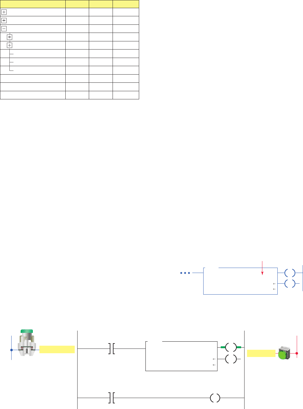
Figure 15-45 shows a TON timer used to delay the op-
eration of a diverter gate solenoid for 3 seconds after a tar-
get has been sensed by the solenoid energize sensor. The
operation of the program can be summarized as follows:
• Detection of the target causes closure of the SOL_
Energize_Sensor contacts making the timer rung
true and start timing.
• With passage of the target the SOL_Energize_
Sensor contacts open but the rung remains true
through the EN bit of the TON timer.
• After 3000 ms (3 s) delay time has elapsed, delay
timer DN bit is set to 1 to energize the SOL_Gate.
Figure 15-42 TON on-delay instruction.
TON TOF RTO
Add-OnFavorites Alarms Bit
CTU CTD RES
Timer/Counter
Tag name
Input side of rung
TIMER ON DELAY
Timer
Preset
Accum
Solenoid_Delay
3000
0
TON
EN
DN
Figure 15-43 Timer tag validation.
Diverter gate
solenoid delay timer
TIMER ON DELAY
Timer
Preset
Accum
Solenoid_Delay
3000
0
TON
EN
DN
Programming Timers Part 3 339
pet10882_ch15_317-372.indd 339pet10882_ch15_317-372.indd 339 7/27/10 6:43 PM7/27/10 6:43 PM
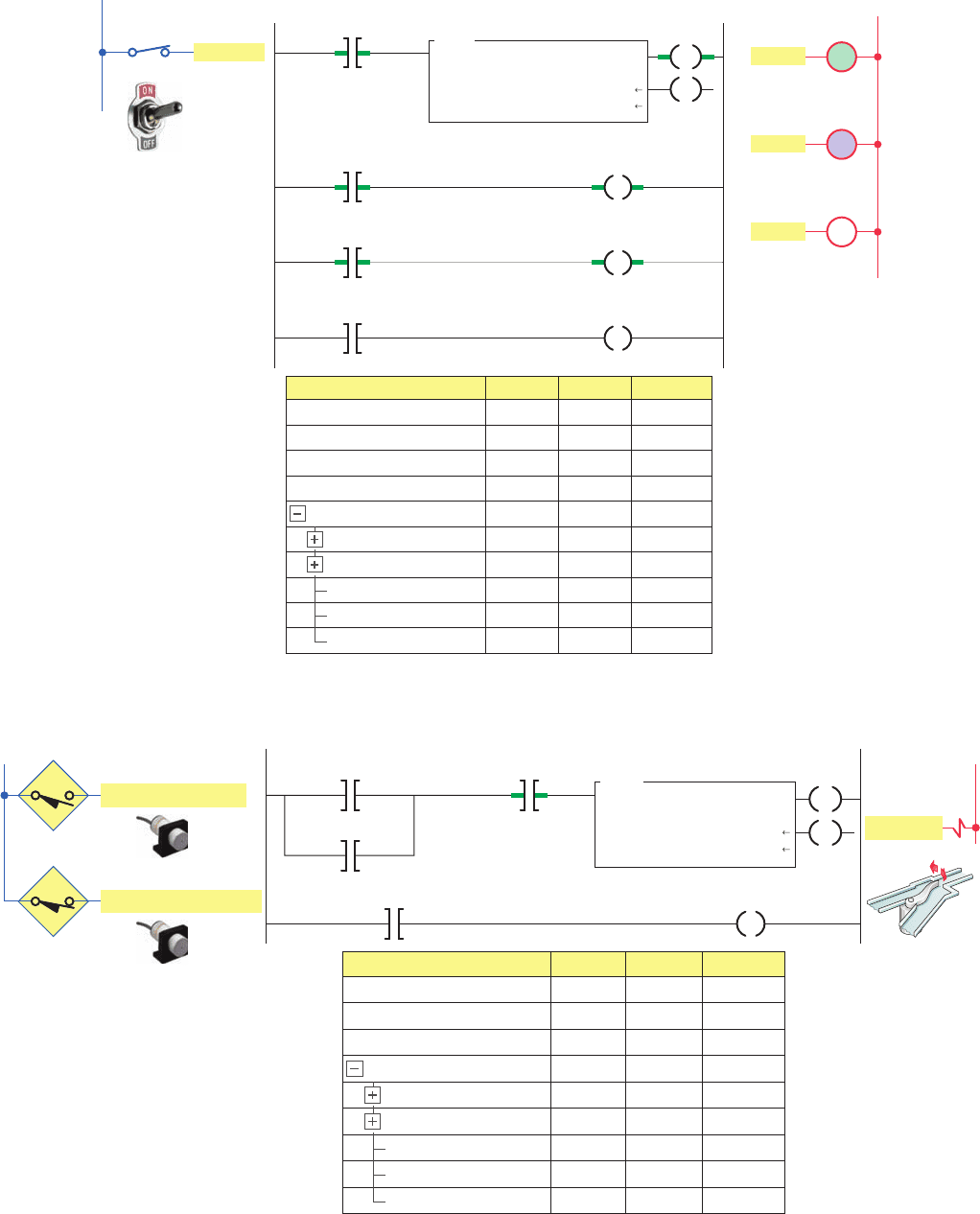
Figure 15-45 TON timer used to delay the operation of a diverter gate solenoid.
Source: Photos courtesy Omron Industrial Automation, www.ia.omron.com.
Tag Name Value Style Data Type
SOL_Energize_Sensor 0
{…}
3000 Decimal
Decimal
DINT
DINT
BOOL
BOOL
BOOL
Decimal
Decimal
Decimal
Decimal
0
0
0
0
BOOL
SOL_Deenergize_Sensor 1 Decimal BOOL
SOL_Gate 0 Decimal BOOL
TIMERT_SOL_Delay
T_SOL_Delay.PRE
T_SOL_Delay.ACC
T_SOL_Delay.EN
T_SOL_Delay.TT
T_SOL_Delay.DN
Ladder logic program
L1
Inputs
L2
Output
SOL_Energize_Sensor
<Local:1:I.Data.3>
SOL_De-energize_Sensor
<Local:1:I.Data.6>
T_SOL_Delay.EN
T_SOL_Delay
TON
TIMER ON DELAY
Timer
Preset
Accum
3000
0
EN
DN
T_SOL_Delay.DN
SOL_Gate
<Local:2:O.Data.2>
SOL_Energize_Sensor
SOL_Deenergize_Sensor
SOL_Gate
Figure 15-44 Ten-second TON timer program.
DN
Tag Name Value Style Data Type
Timer_Sw 1
{…}
10000 Decimal
Decimal
DINT
DINT
BOOL
BOOL
BOOL
Decimal
Decimal
Decimal
Decimal
500
1
1
0
BOOL
EN_PL 1 Decimal BOOL
TT_PL 1 Decimal
Decimal
BOOL
TIMER-Status_Timer
Status_Timer.PRE
Status_Timer.ACC
Status_Timer.EN
Status_Timer.TT
Status_Timer.DN
0 BOOLDN_PL
Ladder logic program
Timer_Sw
<Local:1:I.Data.6>
Status_Timer
TO
N
TIMER ON DELAY
Timer
Preset
Accum
10000
5000
EN_PL
<Local:2:O.Data.1>
Status_Timer.EN
Status_Timer.TT
Status_Timer.DN
EN
EN
TT_PL
<Local:2:O.Data.2>
DN_PL
<Local:2:O.Data.3>
OutputsInput
L2
L1
EN_PL
Timer_Sw
TT
TT_PL
DN
DN_PL
340 Part 3 Programming Timers
pet10882_ch15_317-372.indd 340pet10882_ch15_317-372.indd 340 7/27/10 6:43 PM7/27/10 6:43 PM
• When the button is then opened the timer rung
remains true through the logic path created by the
Pilot_Light_Timer.EN bit.
• After 20000 ms (20 s) have elapsed the timer DN
bit is set to reset the timer to its original state and
unlatch the Green_PL and switch it off.
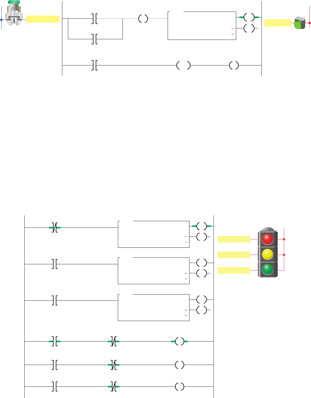
The ControlLogix program of Figure 15-47 shows
three TON timers cascaded (connected together) for traf-
c light control. The ladder logic used is the same as that
used to program the traf c lights using the SLC 500 con-
troller. The different tags created to t the program are
• Momentary detection of the target by the SOL_
Deenergize_Sensor causes the opening of its con-
tacts and resets the program to its original state.
Figure 15-46 shows a program that uses a TON timer to
illuminate a green pilot light for 20 seconds each time a mo-
mentary button is pressed. In addition to the TON timer this
program uses multiple outputs on one rung, output latch and
unlatch instructions, as well as a timer reset instruction. The
operation of the program can be summarized as follows:
• Initially closing the Timer_Button sets (latches) the
Green_PL on and enables the Pilot_Light_Timer.
Figure 15-47 ControlLogix traffi c control program.
Ladder logic program
Amber_Light_Timer.DN
Red_Light_Timer.DN
Red_Light_Timer
Green_Light_Timer.DN
Red_Light_Timer.EN
Green_Light_Timer.EN
Amber_Light_Timer.EN
Red_Light_Timer.DN
Red_Light
<Local:2:O.Data.0>
Green_Light_Timer.DN
Amber_Light_Timer
.DN
TON
TIMER ON DELAY
Timer
Preset
Accum
30000
0
Green_Light_Timer
TON
TIMER ON DELAY
Timer
Preset
Accum
25000
Amber_ Light
Green_ Light
Red_ Light
Outputs
L2
0
Amber_Light_Timer
TON
TIMER ON DELAY
Timer
Preset
Accum
5000
0
EN
DN
Green_Light
<Local:2:O.Data.1>
Amber_Light
<Local:2:O.Data.2>
EN
DN
EN
DN
Figure 15-46 Pilot light TON timer.
Green_ PL
Timer_Button
L2L1
Ladder logic program OutputInput
Green_PL
<Local:2:O.Data.3>
L
Time_Button
<Local:1:
I.Data.0>
Pilot_Light_Timer.EN
Pilot_Light_Timer.DN Pilot_Light_Timer
Green_PL
<Local:2:O.Data.3>
U
RES
Pilot_Light_Timer
TON
TIMER ON DELAY
Timer
Preset
Accum
20000
0
EN
DN
Programming Timers Part 3 341
pet10882_ch15_317-372.indd 341pet10882_ch15_317-372.indd 341 7/27/10 6:43 PM7/27/10 6:43 PM
shown in Figure 15-48 . Operation of the program can be
summarized as follows:
• Transition from red light to green light to amber
light is accomplished by the interconnection of the
EN and DN bits of the three TON timer instructions.
• The input to the Red_Light_Timer is controlled by
the Amber_Light_Timer.DN bit.
• The input to the Green_Light_Timer is controlled
by the Red_Light_Timer.DN bit.
• The input to the Amber_Light_Timer is controlled
by the Green_Light_Timer.DN bit.
• The timed sequence of the lights is:
- Red—30 s on
- Green—25 s on
- Amber—5 s on
• The sequence then repeats itself.
Off-Delay Timer (TOF)
The off-delay timer (TOF) operates in a fashion opposite
to the TON on-delay timer. An off-delay timer will turn
on immediately when the rung of ladder logic is true,
Figure 15-49 ControlLogix TOF off-delay timer instruction.
Tag name
TOF
TIMER OFF DELA
Y
Timer Sample_TOF
Preset
Accum
5000
0
Input side
of rung
EN
DN
Figure 15-50 Pilot light TOF timer.
Green_ PL
Timer_Button
L2L1
Ladder logic program OutputInput
Timer_Button
<Local:1:
I.Data.0>
Pilot_Light_Timer.DN
Green_PL
<Local:2:O.Data.3>
Pilot_Light_Timer
TOF
TIMER OFF DELAY
Timer
Preset
Accum
20000
0
EN
DN
Figure 15-48 Tags created for traffi c light program.
Tag Name Value Style Data Type
-Amber_Light_Timer {…}
{…}
{…}
30000 Decimal DINT
DINT
BOOL
BOOL
BOOL
BOOL
BOOL
BOOL
Decimal
Decimal
Decimal
Decimal
Decimal
Decimal
Decimal
0
1
1
0
1
0
0
TIMER
TIMER
TIMER
-Green_Light_Timer
-Red_Light_Timer
Red_Light
Green_Light
Amber_Light
-Red_Light_Timer.PRE
-Red_Light_Timer.ACC
Red_Light_Timer.EN
Red_Light_Timer.TT
Red_Light_Timer.DN
but it will delay before turning off after the rung goes
false. The ControlLogix TOF off-delay timer instruction
is shown in Figure 15-49 . The description of the function
block elds and tag references are the same as for that of
a TON timer.
Figure 15-50 shows a program that uses a TOF timer
to illuminate a green pilot light for 20 seconds each time
a momentary button is pressed. The program code is sim-
pler than that used to accomplish the same task using a
TON timer. The operation of the program can be sum-
marized as follows:
• When the Timer_Button is initially closed the
timer rung and instruction and DN bit all become
true.
• The DN bit switches on the Green_PL and the
program remains in this state as long as the button is
held closed.
• When the button is released the Timer_Button
instruction goes false and starts the timing cycle.
• The light remains on and the timer begins accumu-
lating time.
• When the accumulator reaches 20000 ms (20 s)
the timer DN bit becomes false and the light is
switchedoff.
The program of Figure 15-51 uses both on-delay and
off-delay timers for control of a heating oven process.
The different tags created to t the program are shown
342 Part 3 Programming Timers
pet10882_ch15_317-372.indd 342pet10882_ch15_317-372.indd 342 7/27/10 6:43 PM7/27/10 6:43 PM