Petruzella F.D. Programmable Logic Controllers
Подождите немного. Документ загружается.

Function Block Programming Part 6 363
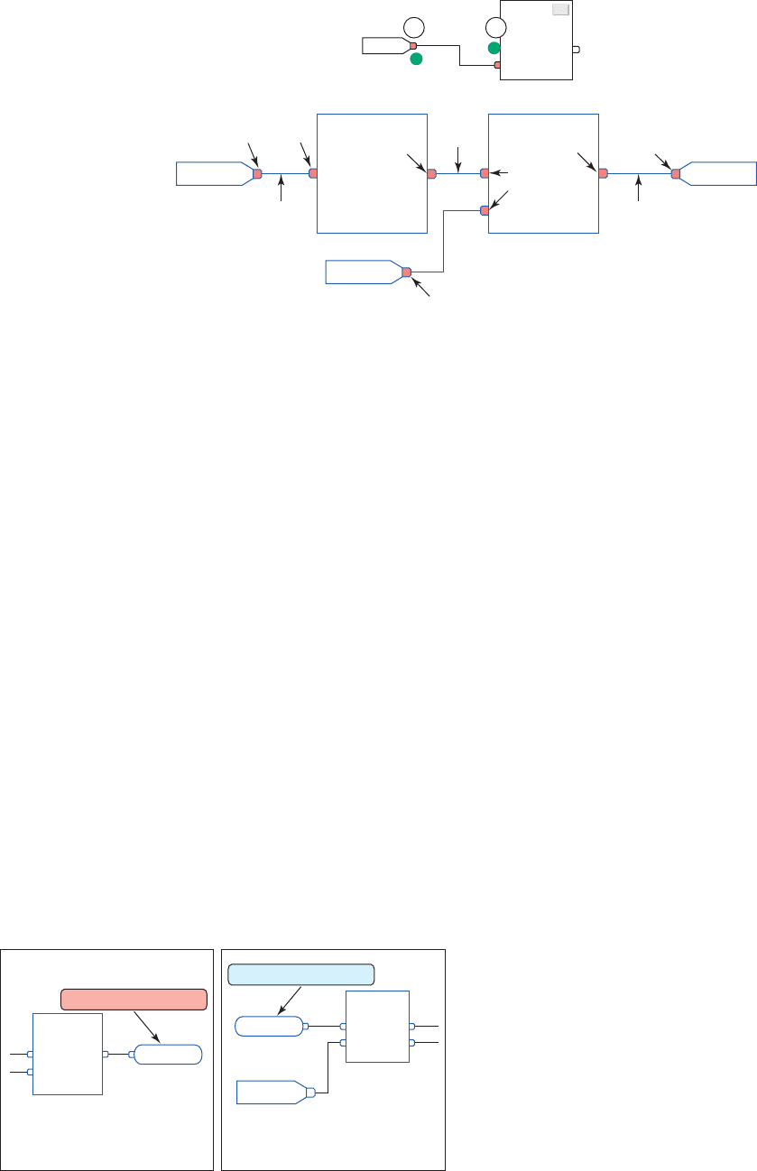
right are output pins. To wire two elements together, click
the output pin of the rst element (A) and then click the
input pin of the other element (B). A green dot shows a
valid connection point.
Wire connectors are used to create a path without
usinga wire. When there are many function blocks on a
sheet, or the function blocks are far apart, wire connectors
used in place of wires can make the logic harder to read.
Wire connectors are also used to connect function blocks
that are on a different sheet of the same function block
routine, as illustrated in Figure 15-85 . The use of wire
connectors can be summarized as follows:
• An output wire connector, or OCON , sends a value
or signal to an input wire connector, or ICON .
• Each output wire connector must have at least one
corresponding input wire connector.
• Each output wire connector requires a unique tag
name and the corresponding input connector must
have the same name.
• Multiple input wire connectors can reference
thesame output wire connector. This lets you
share data at several points in your function block
diagram.
Figure 15-86 illustrates the signal ow and execution
of an FBD program. The operation can be summarized as
follows:
• Each program scan sets all the FBD blocks starting
on the left side of the signal ow and continues to
evaluate all blocks according to the signal ow until
the nal output is determined.
• The location of a block does not affect the order in
which the blocks execute.
• The inputs of a block require data to be available
before the controller can execute that block.
• If function blocks are not wired together, it does not
matter which block executes rst as there is no data
ow between the blocks.
• The interconnected line between the blocks indi-
cates what type of signal is present.
Data latching refers to how the controller veri es
that the data present at the input to a function block are
valid. If you use an IREF to specify input data for a func-
tion block instruction, as illustrated in Figure15- 87 , the
data in that IREF are latched (won’t change) for the
scan of the function block routine. The IREF latches
data from program-scoped and controller-scoped tags.
The controller updates all IREF data at the beginning
of each scan. A function block routine executes in the
following order:
• The controller latches all data values in IREFs.
Figure 15-84 Function block diagram wire and pins.
Input
pin
Wire
Output
pin
Output
pin
Output
pin
Output
pin
Input
pin
Input
pins
Wire
Wire
Wiring elements
...
A B
Figure 15-85 OCON and ICON wire connectors.
Speed
Speed
OCON
ICON
Sheet 1
Output wire connector
Sheet 2
Output wire connector
pet10882_ch15_317-372.indd 363pet10882_ch15_317-372.indd 363 7/27/10 6:43 PM7/27/10 6:43 PM
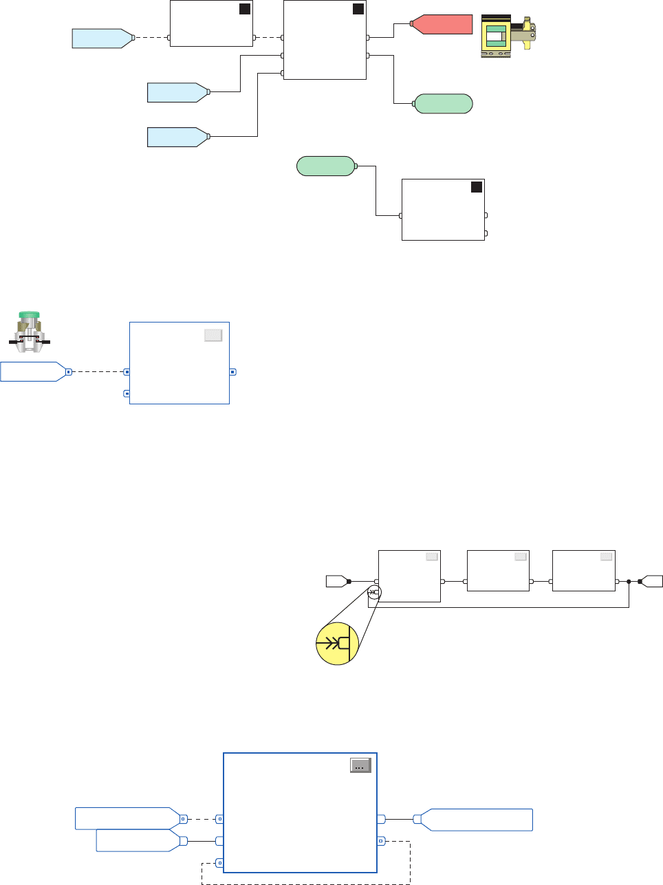
When a group of function blocks are in a feedback
loop, the controller cannot determine which block to
execute rst. This problem is resolved by placing an
Assume Data Available indicator mark at the input pin
of the function block that should be executed rst. In the
example shown in Figure 15-89 , the input for block 1
uses the data from block 3 that were produced in the
previous scan. To place the indicator click on the inter-
connecting wire and select the Assume Data Available
choice.
• The controller executes the other function blocks
inorder.
• The controller writes outputs in OREFs.
To create a feedback loop around a block, wire an out-
put pin of the block to an input pin of the same block.
The input pin will receive the value of the output that was
produced on the last scan of the function block. The loop
contains only a single block, so execution order does not
matter. Figure 15-88 shows an example of a feedback loop
used to reset an on-delay timer. When the timer nishes
timing its DN bit is used to reset the timer.
Figure 15-87 IREF is latched for the scan of the function
block routine.
...
Start_PB
IREF
Figure 15-88 Feedback loop used to reset an on-delay timer.
TONR_01
TONR
Timer On Dela
y with Reset
TimerEnable
PRE
ACC
DN
Reset
Feedback loop
Timer_Enab
le_Bit
Preset_Value
Accumulated_Time
Figure 15-86 Signal fl ow and execution of an FBD program.
Function block
Input reference
Input reference
Output reference
Solenoid
Output wire
connector
Input wire
connector
Input reference
Function block
IREF
OREF
OCON
ICON
IREF
IREF
Function block
Figure 15-89 Assume Data Available indicator marker.
...
Feedback loop
Assume Data
Available indicator
Block 1
...
Block 2
...
Block 3
364 Part 6 Function Block Programming
pet10882_ch15_317-372.indd 364pet10882_ch15_317-372.indd 364 7/27/10 6:43 PM7/27/10 6:43 PM
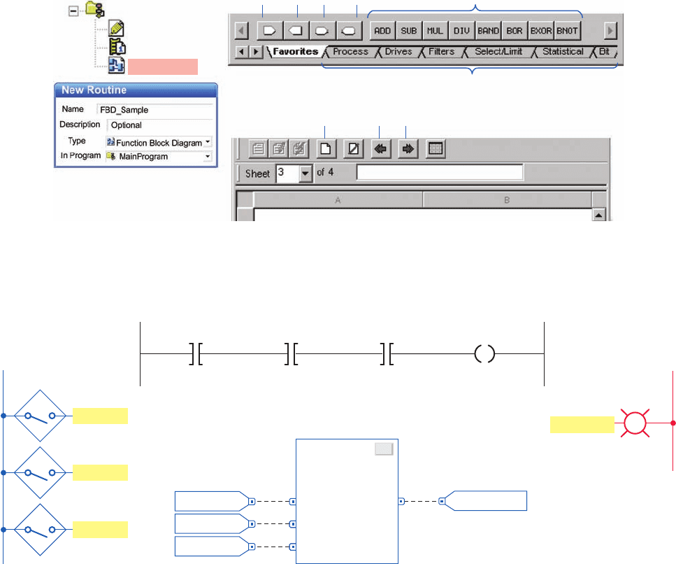
FBD Programming
Figure 15-90 illustrates the setup procedure for FBD pro-
gramming. The steps to be followed can be summarized
as follows:
• Right click on the MainProgram le and select New
Routine from the pop-up menu.
• Select the Function Block diagram entry from the
Type window.
• Enter a name for the Routine (e.g., FDB_Sample).
• You will now see the new program (FDB_Sample)
listed under MainProgram.
• Left clicking the FBD_Sample twice opens the
graphic development window.
• FBD instructions selected from the Language Element
toolbar are used in the development of the program.
• Extra sheets can be added when the current sheet is
full by clicking the add sheet icon. Movement be-
tween sheets is provided by left and right arrows.
The MainRoutine is always a ladder logic program in
RSLogix 5000 software, and all other routines are called
from the MainRoutine. Therefore, the MainRoutine will
have one unconditional rung with a jump to subroutine
(JSR) calling FBD_Sample. The FBD program will ex-
ecute from the JSR instruction. No subroutine or return
subroutine instruction in the FBD is necessary.
Function block programs are similar to ladder logic
programs, except that the process is visualized in the form
of function blocks instead of ladder rungs. Figure 15-91
shows a comparison between ladder logic and the FBD
equivalent for a three-input AND ladder logic rung. The
operation of the FBD can be summarized as follows:
Figure 15-90 Setup procedure for FDB programming.
IREF OREF ICON
Add sheet
MainProgram
Move Sheet
OCON
Function blocks
Other function blocks
Program Tags
MainRoutine
FBD_Sample
Figure 15-91 Comparison between ladder logic and the FBD equivalent for a three-input AND ladder logic rung.
Caution_PL
...
BAND_01
BAND
Boolean And
In1
In2
Out
In3
Sensor_1
Ladder logic
FBD equivalent
Output
L2
Caution_PL
Sensor_1
<Local:1:I.Data.1>
Sensor_2
<Local:1:I.Data.2>
Sensor_3
<Local:1:I.Data.3>
00
Sensor_2
0
Sensor_3
0
Caution_PL
<Local:2:O.Data.4>
L1
Inputs
Sensor_1
Sensor_2
Sensor_3
Function Block Programming Part 6 365
pet10882_ch15_317-372.indd 365pet10882_ch15_317-372.indd 365 7/27/10 6:43 PM7/27/10 6:43 PM
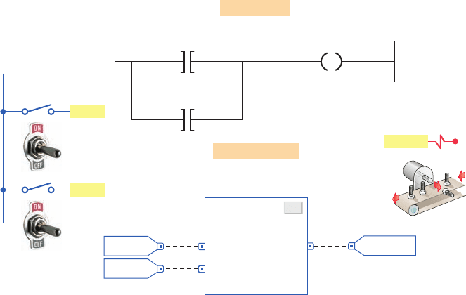
• When the inputs represented by Sensor_1, Sensor_2,
and Sensor_3 are true (value 1) the BAND (Boolean
AND) function block will be true.
• The BAND block executes to set output Caution_PL
true and switch the pilot light on.
• The 0 to the right of the input reference and out pin
indicates its logic state. A 0 indicates the state of the
tag is false, while a 1 signi es it is true.
• The same eld input sensors and output pilot
lightdevices and tags can be used with either
program.
• The XIC and OTE contact and coil instructions have
been replaced by the BAND function block.
Figure 15-92 shows a comparison between ladder
logic and the FBD equivalent for a two-input OR lad-
der logic rung. As with ladder OR logic, if any of the
two inputs is true the BOR function block will be true.
In this example, with the BOR function block true, the
output reference tag SOL_1 will be true energizing the
solenoid.
Figure 15-93 shows a comparison between ladder logic
and the FBD equivalent for a combination of multiple in-
puts. The operation of the FBD can be summarized as
follows:
• The alarm will be energized if either input In1 or
In2 to the BOR block is true.
• Input In2 of the BOR block will be true only when
all three of the sensor switches are closed.
• Input In1 of the BOR block will be true only when
the Temp_Sw is closed at the same time as the
Press_Sw is open.
• The BNOT function block executes similarly to an
XIO ladder logic contact instruction. When In is 0,
Out is 1 and vice versa.
Figure 15-94 shows a comparison between ladder logic
and the FBD equivalent for the motor start/stop control
circuit. The logic sequence for starting and stopping the
motor can be summarized as follows:
• When Motor_Start button is closed the BOR output
will become true making the BAND output true.
• Motor_Run output energizes the contactor coil, the
contacts of which close to start the motor operating.
• When the Motor_Start button is then opened
theoutput of the BOR block remains true due to
the1 status of the feedback signal from the
Motor_Run tag.
• When the Motor_Stop button is opened the output
of the BAND block turns false to de-energize the
contactor coil and stop the motor.
Figure 15-95 shows a comparison between ladder logic
and the FBD equivalent for the 10 second TON (on-delay
Figure 15-92 Comparison between ladder logic and the FBD equivalent for a
two-input OR ladder logic rung.
SOL_1
...
BOR_01
BOR
Boolean Or
In1
In2
Out
Sw_1
FBD equivalent
00
Sw_2
0
Sw_1
<Local:1:I.Data.3>
Sw_2
<Local:1:I.Data.4>
SOL_1
<Local:2:O.Data.4>
Ladder logic
Inputs
L1
Sw_1
Sw_2
L2
Output
SOL_1
366 Part 6 Function Block Programming
pet10882_ch15_317-372.indd 366pet10882_ch15_317-372.indd 366 7/27/10 6:43 PM7/27/10 6:43 PM

Figure 15-93 Comparison between ladder logic and the FBD equivalent for a combination of multiple inputs.
FBD equivalent
Alarm
...
BAND_01
BAND
Boolean And
In1
In2
Out
Temp_Sw
0
0
Press_Sw
01
Sensor_1
0
Sensor_2
0
Sensor_3
0
...
BOR_01
BOR
Boolean Or
In1
In2
Out
0
...
BAND_02
BAND
Boolean And
In1
In2
Out
0
In3
...
BNOT_01
BNOT
Boolean Not
In
Out
Temp_Sw
<Local:1:I.Data.1>
Sensor_1
<Local:1:I.Data.3>
Sensor_2
<Local:1:I.Data.4>
Press_Sw
<Local:1:I.Data.2>
Sensor_3
<Local:1:I.Data.5>
Alarm
<Local:2:O.Data.4>
Ladder logic
Inputs
Temp_Sw
L1
Sensor_1
Sensor_2
Sensor_3
Press_Sw
L2
Output
Alarm
Alarm
Figure 15-94 Comparison between ladder logic and the FBD equivalent for a motor start/stop
control circuit.
...
BAND_01
BAND
Boolean And
In1
In2
Out
0
1
Start button for
motor
Motor_Start
Stop button for
motor
Motor_Stop
Motor
contactor coil
Motor_Run
0
Start button for
motor
Motor_Start
<Local:1:I.Data.3>
Motor contactor coil
Motor_Run
<Local:2:O.Data.4>
Stop button for
motor
Motor_Stop
<Local:1:I.Data.4>
Motor contactor coil
Motor_Run
<Local:2:O.Data.4>
Ladder logic
...
BOR_01
BOR
Boolean Or
In1
In2
Out
0
Inputs
L1
Motor_Start
Motor_Stop
Start
Stop
FBD equivalent
L2Output
C
Motor_Run
Function Block Programming Part 6 367
pet10882_ch15_317-372.indd 367pet10882_ch15_317-372.indd 367 7/27/10 6:43 PM7/27/10 6:43 PM
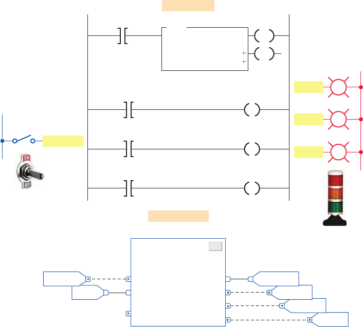
Figure 15-96 shows a comparison between ladder logic
and the FBD equivalent for the Up/Down counter used to
limit the number of parts stored in a buffer zone to 50. The
operation of the FBD can be summarized as follows:
• The CTUD up/down counter function block accu-
mulated value is initially reset by momentary actua-
tion of the Restart_Button.
• The accumulated count is monitored by the output
reference tag named ACC.
• Each time a part enters the buffer zone, the Enter_
Limit_Sw is actuated and the CUEnable input turns
true to increment the count by 1.
• Each time a part exits the buffer zone, the Exit_
Limit_Sw is actuated and the CDEnable input turns
true to decrement the count by 1.
• Whenever the number of parts in the buffer zone
reaches 50 the DN bit is set to 1 and the output of
the BNOT block is reset to zero. This de-energizes
the Conveyor_Contactor to stop the conveyor motor
from delivering more parts to the buffer zone.
timer) and TONR (on-delay with reset). The operation of
the FBD can be summarized as follows:
• When the Timer_Sw is closed, the TONR func-
tionblock timer turns true and starts accumulating
time.
• The accumulated time is monitored by the output
reference tag named ACC.
• The EN (enable bit) output changes to 1 to turn on
the EN_PL.
• The TT (timer timing bit) output changes to 1 to
turn on the TT_PL.
• The timer times out after 10 seconds to set the DN
(done bit) to 1 and turn on the DN_PL and reset the
TT bit to zero and turn off the TT_PL.
• The EN bit and EN_PL remain on as long as the
Timer_Sw stays toggled closed.
• Opening the Timer_Sw resets all outputs as well as
the accumulated value to zero.
• The timer can also be reset by way of the Reset
input.
10000
0
DN_PL
0
TT_PL
0
EN_PL
Status_Timer.DN
DN_PL
<Local:2:O.Data.3>
Status_Timer.TT
Input
L1
TT_PL
<Local:2:O.Data.2>
Status_Timer.EN
EN
Timer On Delay
Timer
Preset
Accum
Status_Timer
10000
0
EN_PL
<Local:2:O.Data.1>
DN
Timer_Sw
<Local:1:I.Data.6>
TON
Ladder logic
FBD equivalent
TONR_01
...
TONR
Timer On Delay with Reset
TimerEnable ACC
PRE
Reset
EN
TT
DN
Timer_Sw
Outputs
L2
TT_PL
EN_PL
0
ACC_Value
0
10000
Timer_Sw
DN_PL
Figure 15-95 Comparison between ladder logic and the FBD equivalent for a
10second TON and TONR timer.
368 Part 6 Function Block Programming
pet10882_ch15_317-372.indd 368pet10882_ch15_317-372.indd 368 7/27/10 6:43 PM7/27/10 6:43 PM

• Using one sheet for each device that is to be pro-
grammed helps organize your program and make it
easier to understand.
• The use of the OCON and ICON named ACC
enables the function blocks to be on different sheets
of the same function block routine.
• The numbers and letters under the ACC output
indicate the sheet number and location on the sheet
where the output is used.
Figure 15-97 shows a comparison between ladder logic
and the FBD equivalent for the program used to test the
accumulated value of a counter. The operation of the FBD
can be summarized as follows:
• The function block routine is broken into four
sheets.
• The order of the sheets does not affect the order in
which the function blocks execute.
• When a function block routine executes, all sheets
execute.
50
50
0
Exit_Limit_Sw
0
Restart_Button
1
Conveyor_Contactor
L1 Inputs
Count Up
Counter
Preset
Accum
Counter_1
50
0
CTU
RES
Counter_1
Restart_Button
<Local:1:I.Data.1>
Enter_Limit_Sw
<Local:1:I.Data.3>
Ladder logic
CTUD_01
...
CTUD
Count Up/Down
CUEnable ACC
CDEnable
PRE
Reset
DN
L2
Output
Conveyor_Contactor
C
...
BNOT
Boolean Not
In Out
0
ACC
0
0
Enter_Limit_Sw
Count Down
Counter
Preset
Accum
Counter_1
50
0
CTD
Counter_1.DN
Exit_Limit_Sw
<Local:1:I.Data.4>
Conveyor_Contactor
<Local:2:O.Data.2>
Restart_Button
Enter_Limit_Sw
Exit_Limit_Sw
FBD equivalent
BNOT_01
CU
DN
CD
DN
Figure 15-96 Comparison between ladder logic and the FBD equivalent for an Up/Down counter
application.
Function Block Programming Part 6 369
pet10882_ch15_317-372.indd 369pet10882_ch15_317-372.indd 369 7/27/10 6:43 PM7/27/10 6:43 PM

25
25
0
L1 Inputs
Count_PB
<Local:1:I.Data.1>
Ladder logic
CTUD_01
...
CTUD
Count Up/Down
CUEnable ACC
CDEnable
PRE
Reset
DN
L2Outputs
PL_1
PL_2
PL_3
0
ACC
2-B2
3-B2
4-B2
0
0
Count_PB
0
Reset_PB
Sheet 1 of 4 Sheet 2 of 4
Sheet 3 of 4 Sheet 4 of 4
C1_DN
PL_1
<Local:2:O.Data.1>
Count_PB
Reset_PB
FBD equivalent
...
BOR
Boolean Or
In2
In1
Out
BOR_01
5
5
10
10
PL_1
0
0
PL_2
GRT_02
...
GRT
Greater Than (A>B)
Source A
Source B Dest
0
0
...
LES
Less Than (A<B)
Source B
Source A
Dest
LES_02
...
BAND
Boolean And
In2
In1
Out
BAND_01
Count Up
Counter
Preset
Accum
C1
25
0
CTU
DN
C1
RES
Less than (A<B)
Source A
Source B
C1.ACC
0
10
LES
Greater than (A>B)
Source A
Source B
C1.ACC
0
5
GRT
PL_2
<Local:2:O.Data.2>
Equal
Source A
Source B
C1.ACC
0
15
EQU
PL_3
<Local:2:O.Data.3>
Reset_PB
<Local:1:I.Data.2>
Not Equal
Source A
Source B
C1.ACC
0
20
NEQ
ACC
0
ACC
0
...
EQU
Equal
SourceB
SourceA
Dest
EQU_01
PL_3
0
ACC
20
20
15
15
1-C2
1-C2
0
...
NEQ
Not Equal
SourceB
SourceA
Dest
NEQ_01
1-C2
CU
Figure 15-97 Comparison between ladder logic and the FBD equivalent for a program used to test the accumulated
value of a counter.
370 Part 6 Function Block Programming
pet10882_ch15_317-372.indd 370pet10882_ch15_317-372.indd 370 7/27/10 6:43 PM7/27/10 6:43 PM

1. Compare the graphical representation of a function
block diagram to that of a logic ladder diagram.
2. Name the four basic elements of an FBD.
3. What do the solid and dashed interconnecting lines
between FBD function blocks indicate?
4. What is an Add-On instruction?
5. How are the input and output parameter options for
a function block set?
6. What does the dot on an input or output pin of a
function block indicate?
7. Compare the functions of input and output refer-
ence tags.
8. Which pins of a function block are inputs and
which are outputs?
9. Explain the role of input and output wire
connectors.
10. How does the program scan function for an FBD
program?
11. Explain data latching as it applies to function block
inputs.
12. How is a function block feedback loop created?
13. What is the Assume Data Available indicator
usedfor?
14. Outline how an FBD program is initiated.
PART 6 REVIEW QUESTIONS
1. Write an FBD program that will cause the output,
solenoid SOL_1, to be energized when pushbutton
PB_1 is open and PB_2 is closed, and either limit
switch LS_1 is open or limit switch LS_2 is closed.
Assume all pushbuttons and limit switches are of the
normally open type.
2. Modify the motor start/stop FBD program to include
a second start/stop pushbutton station.
3. You are required to change the on-delay time of the
10 second timer program to 1 minute. What changes
would have to be made to the FBD program?
4. Modify the Up/Down counter FBD program to
include the following pilot lights:
• PL_1 to come on when a part enters
• PL_2 to come on when a part exits
• PL_3 to come on when the buffer zone is full
5. Modify the test accumulated value of a counter FBD
program as follows:
• PL_1 to be on for an accumulated count between
0 and 5
• PL_2 to be on for an accumulated count of 12
• PL_3 to be on at all times except for when the
accumulated count is 15
PART 6 PROBLEMS
Function Block Programming Part 6 371
pet10882_ch15_317-372.indd 371pet10882_ch15_317-372.indd 371 7/27/10 6:43 PM7/27/10 6:43 PM
pet10882_fm_i-xviii.indd iipet10882_fm_i-xviii.indd ii 7/30/10 5:56 PM7/30/10 5:56 PM
This page intentionally left blank