Petruzella F.D. Programmable Logic Controllers
Подождите немного. Документ загружается.


Data Manipulation Instructions Chapter 10 223
21. Outline the control process involved with simple
PLC set-point control.
22. Compare the operation of the nal control element
in on/off and proportional control systems.
23. Explain the meaning of the following terms as they
apply to a PID control:
a. Process variable
b. Set-point
c. Error
d. Control variable
18. Assume that a thermocouple is connected to an
analog input module. Explain how the tempera-
ture of the thermocouple is communicated to the
processor.
19. Outline the process by which an analog output in-
terface module operates the eld device connected
to it.
20. Compare the operation of open-loop and closed-
loop PLC systems.
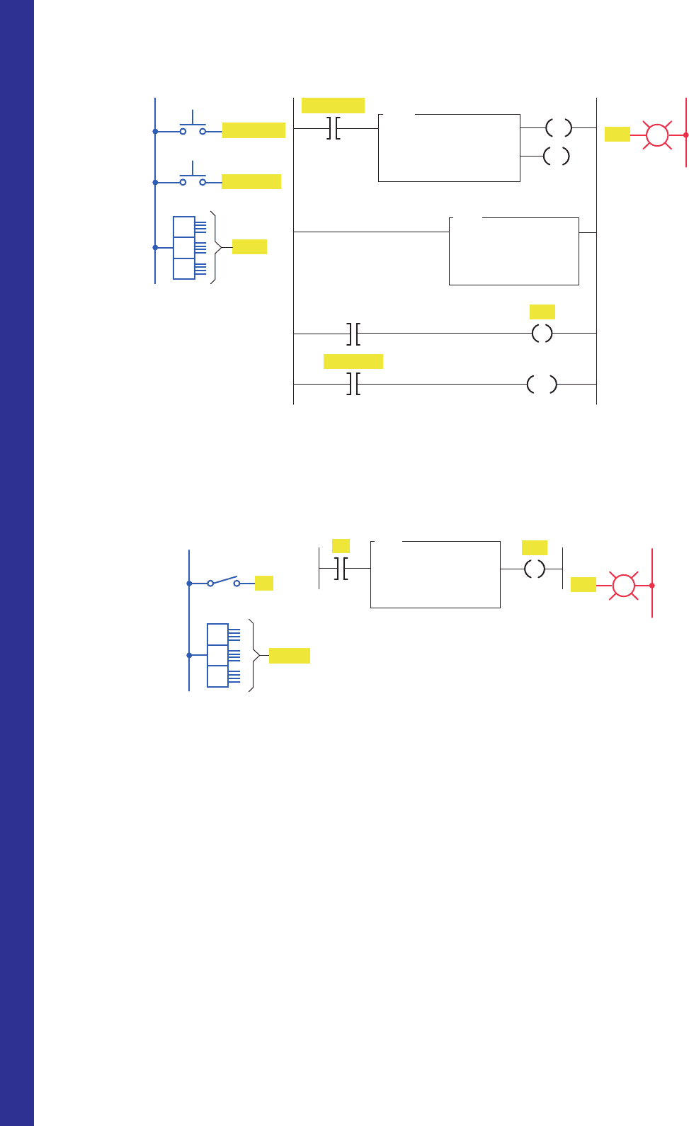
Figure 10-47 Program for Problem 1.
L1
Inputs
L2
OutputLadder logic program
Thumbwheel switch
N7:112
N7:13
LED display
MOV
MOVE
Source
Destination
S1
N7:112
N7:13
4
8
5
S1
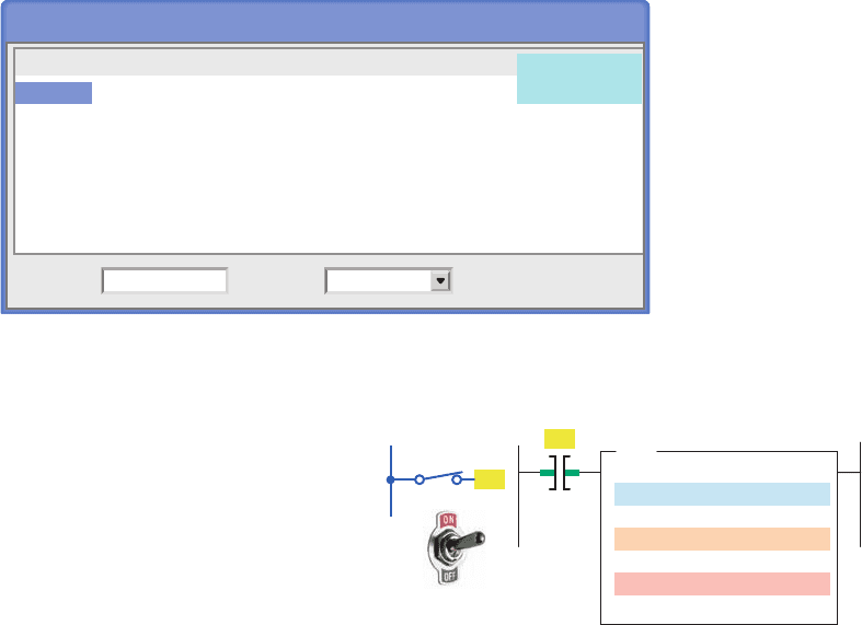
1. Study the data transfer program of Figure10-47
and answer the following questions:
a. When S1 is open, what decimal number will
be stored in integer word address N7:13 of the
MOV instruction?
b. When S1 is on, what decimal number will be
stored in integer word address N7:112 of the
MOV instruction?
c. When S1 is on, what decimal number will ap-
pear in the LED display?
d. What is required for the decimal number 216 to
appear in the LED display?
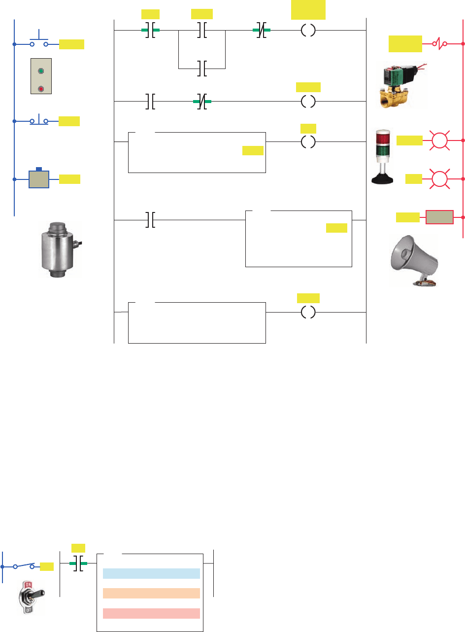
2. Study the data transfer counter program of Fig-
ure10-48 and answer the following questions:
a. What determines the preset value of the
counter?
b. Outline the steps to follow to operate the
program so that the PL1 output is energized
after 25 off-to-on transitions of the count
PB input.
3. Construct a nonretentive timer program that will
turn on a pilot light after a time-delay period. Use
a thumbwheel switch to vary the preset time-delay
value of the timer.
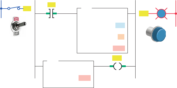
4. Study the data compare program of Figure10-49
and answer the following questions:
a. Will the pilot light PL1 come on whenever
switch S1 is closed? Why?
b. Must switch S1 be closed to change the num-
ber stored in source A of the EQU instruction?
c. What number or numbers need to be set on
the thumbwheel in order to turn on the pilot
light?
CHAPTER 10 PROBLEMS
pet10882_ch10_200-225.indd 223pet10882_ch10_200-225.indd 223 30/07/10 2:08 PM30/07/10 2:08 PM
224 Chapter 10 Data Manipulation Instructions
Figure 10-48 Program for Problem 2.
L1
Count PB
Count PB
Inputs
L2
Output
PL1
PL1
Ladder logic program
N7:10
Reset PB
Reset PB
MOV
MOVE
Source
Destination
N7:10
C5:1.PRE
CTU
COUNT UP
Counter
Preset
Accumulated
C5:1
000
000
DN
CU
RES
C5:1/DN
C5:1
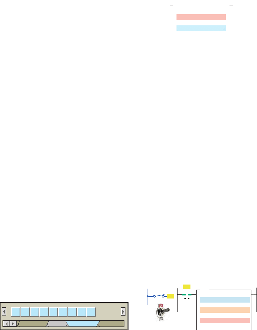
Figure 10-49 Program for Problem 4.
L1
Inputs Ladder logic program
Thumbwheel switch
N7:112
EQU
EQUAL
Source A
Source B
S1
N7:112
004
L2
Output
PL1
PL1
S1
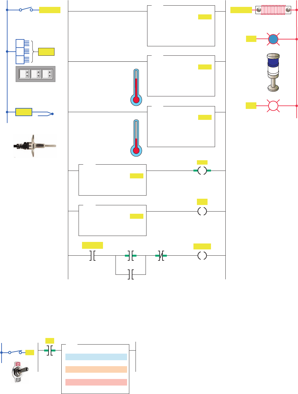
5. Study the data compare program in Figure10-50
and answer the following questions:
a. List the values for the thumbwheel switch that
would allow the pilot light to turn on.
b. If the value in the word N7:112 is 003 and switch
S1 is open, will the pilot light turn on? Why?
c. Assume that source B is addressed to the accu-
mulated count of an up-counter. With S1 closed,
what setting of the thumbwheel switch would be
required to turn the pilot light off when the ac-
cumulated count reaches 150?
6. Write a program to perform the following:
a. Turn on pilot light 1 (PL1) if the thumbwheel
switch value is less than 4.
b. Turn on pilot light 2 (PL2) if the thumbwheel
switch value is equal to 4.
c. Turn on pilot light 3 (PL3) if the thumbwheel
switch value is greater than 4.
d. Turn on pilot light 4 (PL4) if the thumbwheel
switch value is less than or equal to 4.
e. Turn on pilot light 5 (PL5) if the thumbwheel
switch value is greater than or equal to 4.
pet10882_ch10_200-225.indd 224pet10882_ch10_200-225.indd 224 7/27/10 10:45 PM7/27/10 10:45 PM

Data Manipulation Instructions Chapter 10 225
Figure 10-50 Program for Problem 5.
L1
Inputs Ladder logic program
Thumbwheel switch
N7:112
GRT
GREATER THAN
Source A
Source B
S1
N7:112
12
L2
Output
PL1
PL1
S1
11. Write a program that will cause a light to come on
only if a PLC counter has a value of 6 or 10.
12. Write a program that will cause a light to come on if
a PLC counter value is less than 10 or more than 30.
13. Write a program for the following: The tempera-
ture reading from a thermocouple is to be read and
stored in a memory location every 5 minutes for
4hours. The temperature reading is brought in con-
tinuously and stored in address N7:150. File #7:200
is to contain the data from the last full 4-hour
period.
7. Write a program that will copy the value stored at
address N7:56 into address N7:60.
8. Write a program that uses the mask move instruc-
tion to move only the upper 8 bits of the value
stored at address I:2.0 to address O:2.1 and to
ignore the lower 8 bits.
9. Write a program that uses the FAL instruction to
copy 20 words of data from the integer data le,
starting with N7:40, into the integer data le,
starting with N7:80.
10. Write a program that uses the COP instruction to
copy 128 bits of data from the memory area, start-
ing at B3:0, to the memory area, starting at B3:8.
pet10882_ch10_200-225.indd 225pet10882_ch10_200-225.indd 225 7/27/10 10:45 PM7/27/10 10:45 PM
226
Most PLCs have arithmetic function capabilities.
Basic PLC math instructions include add, sub-
tract, multiply and divide to calculate the sum,
difference, product, and quotient of the content
of word registers. The PLC is capable of doing
many arithmetic operations per scan period for
fast updating of data. This chapter covers the
basic mathematical instructions performed by
PLCs and their applications.
Chapter Objectives
After completing this chapter, you will be able to:
11.1 Analyze and interpret math instructions as they apply
to a PLC program
11.2 Create PLC programs involving math instructions
11.3 Apply combinations of PLC arithmetic functions to
processes
11
Math Instructions
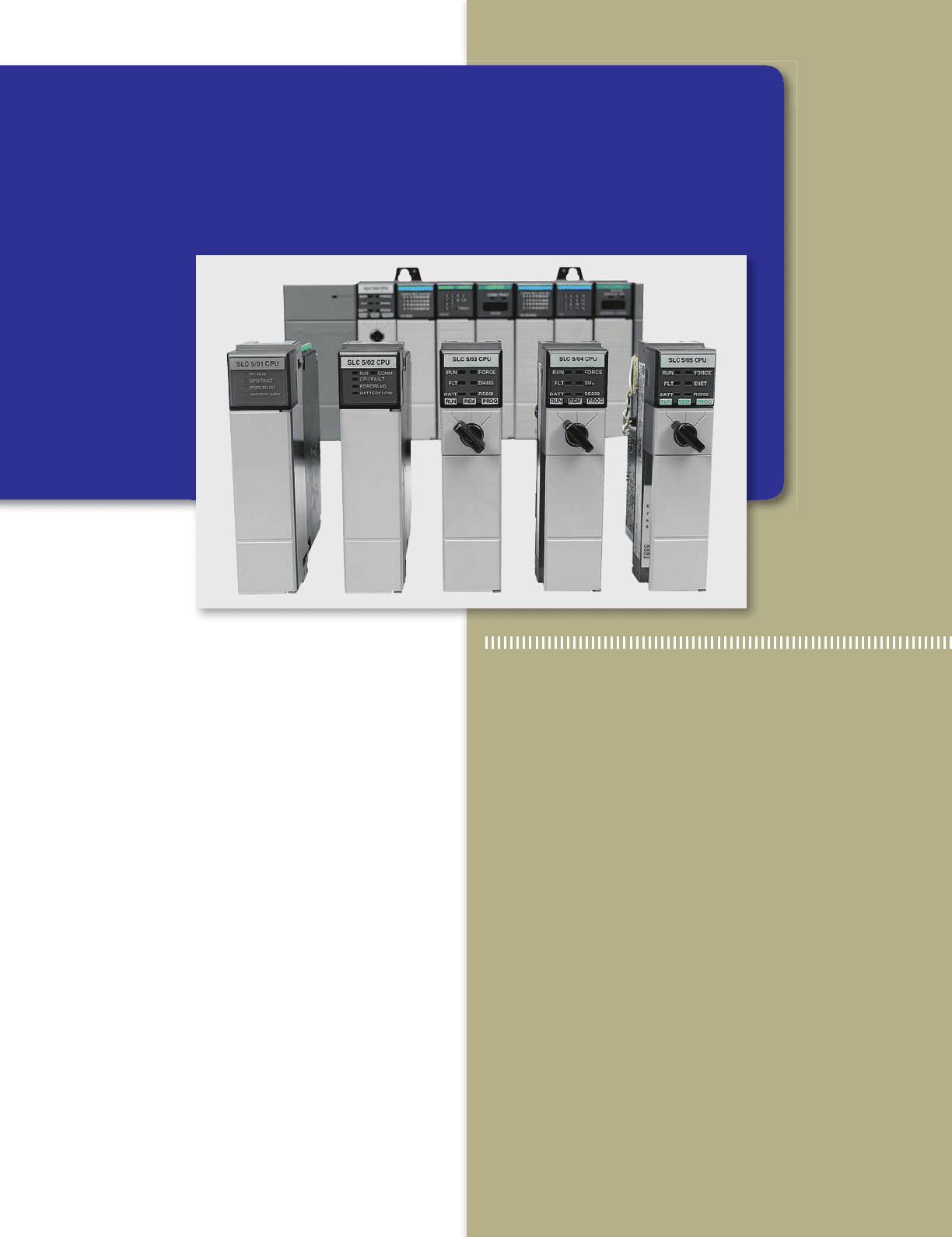
Image Used with Permission of Rockwell Automation, Inc.
pet10882_ch11_226-241.indd 226pet10882_ch11_226-241.indd 226 7/27/10 4:09 PM7/27/10 4:09 PM
Math Instructions Chapter 11 227
DIV (Divide) —Divides source A by source B and
stores the result in the math register.
SQR (Square Root) —Calculates the square root
of the source and places the integer result in the
destination.
NEG (Negate) —Changes the sign of the source and
places it in the destination.
TOD (To BCD) —Converts a 16-bit integer source
value to BCD and stores it in the math register or the
destination.
FRD (From BCD) —Converts a BCD value in the
math register or the source to an integer and stores it
in the destination.
Figure11-2 shows the CPT (compute) instruction used
with SLC 500 controllers. When CPT instruction is ex-
ecuted, then copy, arithmetic, logical, or conversion op-
eration residing in the expression eld of this instruction
is performed and the result is sent to the destination. The
execution time of a CPT instruction is longer than that of
a single arithmetic operation and uses more instruction
words.
11. 2 Addition Instruction
Most math instructions take two input values, perform
the speci ed arithmetic function, and output the result
to an assigned memory location. For example, the ADD
instruction performs the addition of two values stored in
the referenced memory locations. How these values are
accessed depends on the controller. Figure11-3 shows the
11.1 Math Instructions
Math instructions, like data manipulation instructions,
enable the programmable controller to take on more of
the qualities of a conventional computer. The PLC’s math
functions capability allows it to perform arithmetic func-
tions on values stored in memory words or registers. For
example, assume you are using a counter to keep track
of the number of parts manufactured, and you would
like to display how many more parts must be produced
in order to reach a certain quota. This display would re-
quire the data in the accumulated value of the counter to
be subtracted from the quota required. Other applications
include combining parts counted, subtracting detected de-
fects, and calculating run rates.
Depending on what type of processor is used, various
math instructions can be programmed. The basic four
mathematical functions performed by PLCs are:
Addition —The capability to add one piece of data to
another.
Subtraction —The capability to subtract one piece of
data from another.
Multiplication —The capability to multiply one piece
of data by another.
Division —The capability to divide one piece of data
by another.
Math instructions use the contents of two words or
registers and perform the desired function. The PLC in-
structions for data manipulation (data transfer and data
compare) are used with the math symbols to perform
math functions. Math instructions are all output instruc-
tions. Figure11-1 shows the Compute/Math menu tab for
the SLC 500 PLC and its associated RSLogix software.
The commands can be summarized as follows:
CPT (Compute) —Evaluates an expression and stores
the result in the destination.
ADD (add) —Adds source A to source B and stores
the result in the destination.
SUB (Subtract) —Subtracts source B from source A
and stores the result in the destination.
MUL (Multiply) —Multiplies source A by source B
and stores the result in the destination.
Figure 11-1 Compute/Math menu tab.
CPT ADD SUB MUL DIV SQR
Compute/Math
CompareInput/Output
NEG TOD FRD
Move/Logic
Figure 11-2 SLC 500 CPT (compute) instruction.
CPT
Compute
Destination
Expression
Figure 11-3 SLC 500 ADD instruction.
Ladder logic program Input
L1
ADD
ADD
Source A
Source B
Destination
N7:0
25
N7:1
50
N7:2
75
SW
SW
pet10882_ch11_226-241.indd 227pet10882_ch11_226-241.indd 227 7/27/10 4:10 PM7/27/10 4:10 PM
228 Chapter 11 Math Instructions
come on when the sum of the counts from the two coun-
ters is equal to or greater than 350. The operation of the
program can be summarized as follows:
• Source A of the ADD instruction is addressed to
store the accumulated value of counter C5:0.
• Source B of the ADD instruction is addressed to
store the accumulated value of counter C5:1.
• The value at source A is added to the value at source
B, and the result (answer) is stored at destination
address N7:1.
• Source A of the GEQ (greater than or equal) instruc-
tion is addressed to store the value of the destination
address N7:1.
• Source B of the GEQ instruction contains the con-
stant value of 350.
ADD instruction used with the SLC 500 controllers. The
operation of the logic rung can be summarized as follows:
• When input switch SW is closed the rung will be
true.
• The value stored at the source A address, N7:0 (25),
is added to the value stored at the source B address,
N7:1 (50).
• The answer (75) is stored at the destination address
N7:2.
• Source A and source B can be either values or
addresses that contain values, but A and B cannot
both be constants.
The program of Figure11-4 illustrates how the ADD
instruction can be used to add the accumulated counts of
two up-counters. This application requires a pilot light to
Figure 11-4 Counter program that uses the ADD instruction.
L1
Inputs
S2
L2
OutputLadder logic program
S1
C5:0
350
0
CTU
COUNT-UP COUNTER
Counter
Preset
Accumulated
C5:1
350
0
CTU
COUNT-UP COUNTER
Counter
Preset
Accumulated
PL1
C5:0.ACC
C5:1.ACC
N7:1
ADD
ADD
Source A
Source B
Destination
Reset
C5:0
GEQ
GREATER THAN OR EQUAL
Source A
Source B
N7:1
350
CU
DN
CU
DN
RES
C5:1
RES
PL1
Reset
S1
S2
125
100
250
pet10882_ch11_226-241.indd 228pet10882_ch11_226-241.indd 228 7/27/10 4:10 PM7/27/10 4:10 PM
Math Instructions Chapter 11 229
• The GEQ instruction and PL1 output will be true
whenever the accumulated values in the two counters
are equal to or greater than the constant value 350.
• A reset button is provided to reset the accumulated
count of both counters to zero.
When performing math functions, care must be taken
to ensure that values remain in the range that the data
table or le can store; otherwise, the over ow bit will be
set. The arithmetic status bits for the SLC 500 controller
are found in word 0, bits 0 to 3 of the processor status
le S2 ( Figure11-5 ). After an instruction is executed, the
arithmetic status bits in the status le are updated. The
description of each bit can be summarized as follows:
Carry (C)—Address S2:0/0, is set to 1 when there is
a carry in the ADD instruction or a borrow in the SUB
instruction.
Over ow (O)—Address S2:0/1, is set to 1 when the
result is too large to t in the destination register.
Zero (Z)—Address S2:0/2, is set to 1 when the result
of the subtract instruction is zero.
Sign (S)—Address S2:0/3, is set to 1 when the result
is a negative number.
11. 3 Subtraction Instruction
The SUB (subtract) instruction is an output instruction that
subtracts one value from another and stores the result in
the destination address. When rung conditions are true, the
subtract instruction subtracts source B from source A and
stores the result in the destination. Figure11-6 shows the
SUB instruction used with the SLC 500 controllers. The
operation of the logic rung can be summarized as follows:
• When input switch SW is closed the rung will be true.
• The value stored at the source B address, N7:05
(322), is subtracted from the value stored at the
source A address, N7:10 (520).
• The answer (198) is stored at the destination ad-
dress, N7:20.
• Source A and source B can be either values or ad-
dresses that contain values, but A and B cannot both
be constants.
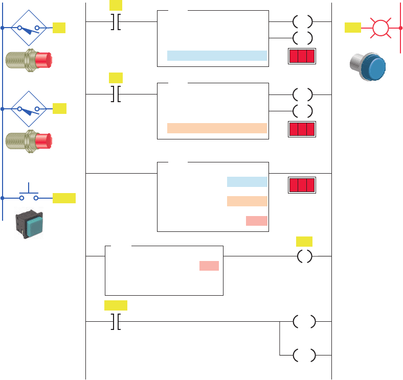
The program of Figure11-7 shows how the SUB func-
tion can be used to indicate a vessel over ll condition.
This application requires an alarm to sound when a supply
system leaks 5 lb or more of raw material into the ves-
sel after a preset weight of 500 lb has been reached. The
operation of the program can be summarized as follows:
• When the start button is pressed, the ll solenoid
(rung 1) and lling indicating light (rung 2) are turned
on and raw material is allowed to ow into the vessel.
• The vessel has its weight monitored continuously by
the PLC program (rung 3) as it lls.
• When the weight reaches 500 lb, the ll solenoid is
de-energized and the ow is cut off.
• At the same time, the lling pilot light indicator is
turned off and the full pilot light indicator (rung 3)
is turned on.
• Should the ll solenoid leak 5 lb or more of raw
material into the vessel, the alarm (rung 5) will en-
ergize and stay energized until the over ow level is
reduced below the 5-lb over ow limit.
Figure 11-5 Processor status fi le S2.
Status Table
Address
S2:0
Table:
S2:Status
15 14 13 12 11 10 9 8 7 6 5 4 3 2 1 0
S2:0/ 0 0 0 0 0 0 0 0 0 0 0 0 0 0 0 0
S2:1/ 0 0 0 0 0 0 0 0 0 0 0 0 0 0 0 0
S2:2/ 0 0 0 0 0 0 0 0 0 0 0 0 0 0 0 0
S2:3/ 0 0 0 0 0 0 0 0 0 0 0 0 0 0 0 0
S2:4/ 0 1 0 0 0 0 0 1 1 0 0 0 0 0 0 1
S2:5/ 0 0 0 0 0 0 0 0 0 0 0 0 0 0 0 0
Figure 11-6 SLC 500 SUB (subtract) instruction.
Ladder logic program Input
L1
SUB
SUBTRACT
Source A
Source B
Destination
N7:10
520
N7:05
322
N7:20
198
SW
SW
pet10882_ch11_226-241.indd 229pet10882_ch11_226-241.indd 229 7/27/10 4:10 PM7/27/10 4:10 PM
230 Chapter 11 Math Instructions
11. 4 Multiplication Instruction
The multiply (MUL) instruction is an output instruction
that multiplies two values and stores the result in the des-
tination address. Figure11-8 shows the MUL instruction
used with the SLC 500 controllers. The operation of the
logic rung can be summarized as follows:
• When input switch SW is closed the rung will be
true.
• The data in source A (constant 20) will be multi-
plied by the data in source B (accumulated value of
counter C5:10).
• The resultant answer is placed in the destination
N7:2.
• Similar to previous math instructions, source A and
B in multiplication instructions can be values (con-
stants) or addresses that contain values, but A and B
cannot both be constants.
The program of Figure 11-9 is an example of how
MUL instruction calculates the product of two sources.
The operation of the program can be summarized as
follows:
• When input switch SW is closed the MUL instruc-
tion is executed.
• The value stored in source A, address N7:1 (123),
is then multiplied by the value stored in source B,
address N7:2(61).
Figure 11-7 Vessel overfi ll alarm program.
Ladder logic program
Full
Full
Fill
solenoid
Fill
solenoid
Fill
solenoid
Alarm
Full
Full
Filling
Outputs
L2
Start
Inputs
L1
Weight
transducer
(All 16 bits)
Stop
SUB
SUBTRACT
Source A
Source B
Destination
Ι:012
500
N7:1
GEQ
GREATER THAN OR EQUAL
Source A
Source B
Ι:012
500
GEQ
GREATER THAN OR EQUAL
Source A
Source B
N7:1
5
1
2
3
4
5
Start
Ι:012
Stop
Full
Fill
solenoid
Alarm
Filling
Start
Stop
Figure 11-8 SLC 500 MUL (multiply) instruction.
Ladder logic program Input
L1
SW
SW
MUL
MULTIPLY
Source A
Source B
Destination
20
C5:10.ACC
N7:2
pet10882_ch11_226-241.indd 230pet10882_ch11_226-241.indd 230 7/27/10 4:10 PM7/27/10 4:10 PM
Math Instructions Chapter 11 231
• The product (7503) is placed into destination word
N7:3.
• As a result, the equal instruction becomes true, turn-
ing output PL1 on.
The program of Figure11-10 is an example of how the
MUL instruction is used as part of an oven temperature
control program. The operation of the program can be
summarized as follows:
• The PLC calculates the upper and lower deadband,
or off/on limits, about the set-point.
• Upper and lower temperature limits are set automati-
cally at 61 percent regardless of the set-point value.
• Set-point temperature is adjusted by means of the
thumbwheel switch.
• The analog thermocouple interface module is used
to monitor the current temperature of the oven.
• In this example, the set-point temperature is 400°F.
• Therefore, the electric heaters will be turned on when
the temperature of the oven drops to less than 396°F
and stay on until the temperature rises above 404°F.
• If the set-point is changed to 100°F, the deadband
remains at 61 percent, with the lower limit being
99°F and the upper limit being 101°F.
• The number stored in word N7:1 represents the
upper temperature limit, and the number stored in
word N7:2 represents the lower limit.
11. 5 Division Instruction
The divide (DIV) instruction divides the value in source A
by the value in source B and stores the result in the desti-
nation and math register. Figure11-11 shows an example
of the DIV instruction. The operation of the logic rung
can be summarized as follows:
• When input switch SW is closed the rung will be true.
• The data in source A (the accumulated value of
counter C5:10) is then divided by the data in source B
(the constant 2).
• The result is placed in the destination N7:3.
• If the remainder is 0.5 or greater, a roundup occurs
in the integer destination.
• The value stored in the math register consists of the
unrounded quotient (placed in the most signi cant
word) and the remainder (placed in the least signi -
cant word).
• Some PLCs support the use of oating-decimal as
well as integer (whole number) values. As an exam-
ple, 10 divided by 3 may be expressed as 3.333333
( oating-decimal notation) or 3 with a remainder
of1.
The program of Figure11-12 is an example of how the
DIV instruction calculates the integer value that results
from dividing source A by source B. The operation of the
program can be summarized as follows:
• When input switch SW is closed the DIV instruc-
tion is executed.
• The value stored in source A, address N7:0 (120),
is then divided by the value stored in source B,
address N7:1 (4).
• The answer, 30, is placed in the destination address
N7:5.
• As a result, the equal instruction becomes true, turn-
ing output PL1 on.
Figure 11-9 MUL instruction used to calculate the product of two sources.
Ladder logic program
OutputInput
L2
PL1
MUL
MULTIPLY
Source A
Source B
Destination
N7:1
123
N7:2
61
N7:3
7503
EQU
EQUAL
Source A
Source B
N7:3
7503
7503
PL1
L1
SW
SW
pet10882_ch11_226-241.indd 231pet10882_ch11_226-241.indd 231 7/27/10 4:10 PM7/27/10 4:10 PM
232 Chapter 11 Math Instructions
The program of Figure 11-13 is an example of how
the DIV function is used as part of a program to convert
Celsius temperature to Fahrenheit. The operation of the
program can be summarized as follows:
• The thumbwheel switch connected to the input
module indicates Celsius temperature.
• The program is designed to convert the recorded
Celsius temperature in the data table to Fahrenheit
values for display.
Figure 11-10 The MUL instruction used as part of a temperature control program.
Ladder logic program
ON/OFF
PL1 PL2
Heater
Heater
PL2
PL1
MUL
MULTIPLY
Source A
Source B
Destination
Ι:012
400
0.0100000
N7:0
4
ADD
ADD
Source A
Source B
Destination
High limit
Low limit
Ι:012
400
N7:0
4
N7:1
404
SUB
SUBTRACT
Source A
Source B
Destination
Ι:012
400
N7:0
4
N7:2
396
LES
LESS THAN
Source A
Source B
Ι:013
0
N7:2
396
GRT
GREATER THAN
Source A
Source B
Ι:013
0
N7:1
404
Inputs
L1
ON/OFF
TWS
Thermocouple
input
1
2
3
Ι:013
Ι:012
PL1
PL2
4 0 0
Heater
L2
Outputs
Figure 11-11 SLC 500 DIV (divide) instruction.
Ladder logic program Input
L1
DIV
DIVIDE
Source A
Source B
Destination
C5:10.ACC
2
N7:3
SW
SW
pet10882_ch11_226-241.indd 232pet10882_ch11_226-241.indd 232 7/27/10 4:10 PM7/27/10 4:10 PM