Nof S.Y. Springer Handbook of Automation
Подождите немного. Документ загружается.

Semiconductor Manufacturing Automation 52.3 Equipment Integration Architecture and Control 915
Single-slot
chamber
Multi-slot
chamber
Va cuuming and
pumping buffer
Loadlock
a) b) c)
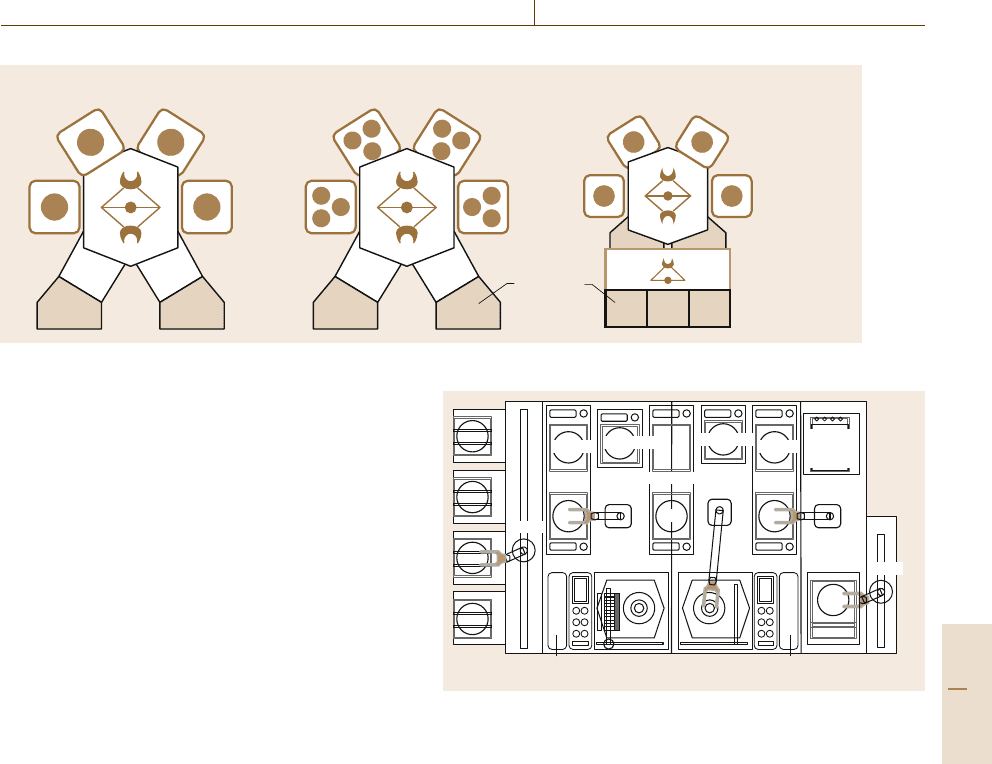
Fig. 52.3a–c Tool architectures: (a) single-slot cluster tool, (b) multi-slot cluster tool, (c) tool with intermediate buffers
velop the circuit patterns on the wafers that are formed
by exposures to circuit pattern picture images at the
steppers. Process modules for coating and develop-
ing, and accompanying baking and cooling modules
are combined into a track tool with several robots, as
illustrated in Fig. 52.4. Each process step has five to
ten parallel modules [52.5, 6]. An automated wet sta-
tion also has a series of chemical and rinsing baths for
cleaning wafer surfaces, which are combined by several
robots moving on a rail [52.7]. Recently, EDS processes
for testing devices on wafers are automated to form
a kind of track system. A number of testing tools for
wafer burn-in (WBI) test, hot pretest, cold pretest, laser
repair, and posttest are configured in series–parallel by
several robots moving on a rail. EDS systems and wet
stations can process several different wafers concur-
rently while most cluster tools or track tools for coating
and developing repeatedly process identical wafers.
Wafers mostly go through a sequence of process
steps in series. For some processes, wafers visit some
process steps again; for instance, unlike conventional
chemical vapor deposition, atomic-layer deposition pro-
cess controls the deposition thickness by repeating
extremely thin deposition multiple times. Therefore,
a wafer reenters the chambers many times. In track sys-
tems, wafer reentrance can be achieved, depending on
the chamber configuration and process recipe. In some
processes, a chamber should be cleaned after a specified
number of wafers have been processed or when sensors
within the chamber detect significant contamination. If
a wafer remains in a chamber after processing, this can
lead to quality problems. This idle time, called wafer
delay, must be bounded, reduced or regulated. Process
times or tasks times are rather constant, but can be sub-
ject to random variation, mostly within a few percent.
There can be exceptional delay, even if only rare, due to
10 coaters
10 cool plates
Loadlocks 10
developers
Interface to
steppers
Robot
Robot
Optical
edge bead
removers
5 bakers
Robot
Robot
5 hot plates
5 hot plates
Module
electronics
Buffer
5 bakers
Robot
Buffer CPx
Buffer
Module
electronics
Fig. 52.4 A track system
abnormal process conditions. A wafer alignment task,
which correctly locates a wafer unloaded from a load-
lock onto a robot arm by using a laser pointing system,
sometimes fails and needs to be retried. Integrated tools
mostly limit intermediate buffers. Therefore, blocking
and waiting are common and even deadlocks can occur.
Reentrance, wafer delays, cleaning cycles, and uncer-
tainty all increase scheduling complexity significantly.
Tool productivity by intelligent scheduling and control
is critical for maximizing fab productivity and even af-
fects wafer quality significantly.
52.3.2 Tool Science: Scheduling and Control
Scheduling Strategies
There can be alternative scheduling strategies for clus-
ter tools. First, a dispatching rule determines the next
robot task depending on the tool state. It can be con-
sidered dynamic and real time. However, it is hard to
optimize the rule. We are only able to compare per-
Part F 52.3
916 Part F Industrial Automation
formances of heuristically designed dispatching rules
by computer simulation. Second, a schedule can be
determined in advance. This method can optimize per-
formance if a proper scheduling model can be defined.
When there is a significant change in the tool situ-
ation, rescheduling is done. Cyclic scheduling makes
each robot and each processing chamber repeat identi-
cal work cycles [52.7,8]. Once the robot task sequence
is determined, all work cycles are determined. Most
academic works on cluster tool scheduling consider
cyclic scheduling. Cyclic scheduling has merits such
as reduced scheduling complexity, predictable behav-
ior, improved throughput, steady or periodical timing
patterns, and regulated or bounded task delays or
wafer delays and work in progress [52.7–10]. In cyclic
scheduling, the timings of taskscan be controlledin real
time whilethe sequenceor workcycle is predetermined.
A cluster tool that repeats identical work cycles can
be formally modeled and analyzed by a timed event
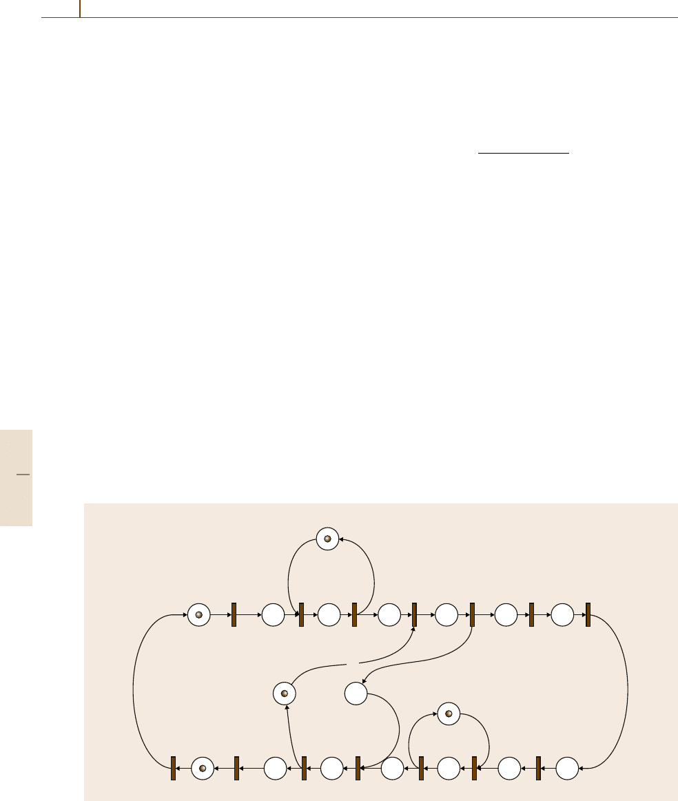
graph (TEG), a class of Petri nets [52.12]. Transitions,
places, arcs, and tokens usually represent activities or
events, conditions or activities, precedence relations
between transitions and places, and entities or condi-
tions, respectively. They are represented graphically by
rectangles, circles, arrows, and dots, respectively. Fig-
ure 52.5 is an example of a TEG model for cluster tools.
Once a TEG model is made, the tool cycle time, the
optimal robot task sequence, the wafer delays, and the
optimal timing schedules can be systematically identi-
P
15
P
1
P
2
P
3
T
1
T
2
P
4
T
3
P
5
T
4
P
6
T
5
P
7
T
6
P
13
P
14
P
12
T
12
T
13
T
14
P
11
T
11
P
10
P
17
P
16
P
18
T
10
P
9
P
8
T
9
T
8
T
7
Unloading complete
robot move
Unloading
from LL
Unloading
Loading
Chamber 1 available
Fig. 52.5 A timed event graph model for a dual-armed cluster tool [52.11]
fied [52.7,9,10]; for instance, the tool cycle time is the
maximum of the circuit ratios in the TEG model, where
the circuit ratio of a circuit is the ratio of the sum of the
total times in the circuit to the number of the tokens in
the circuit. For instance, the cycle time of a dual-armed
cluster tool can be derived from the ratio as
max
max
i=1,...,n
p
i
+2u +2l+3v
m
i
,
(n +1)(u +l +2v)
,
where p
i
, m
i
, u, l, v,andn are the process time of pro-
cess step i, the number of parallel chambers for process
step i, the unloading time, the loading time, the move
time between the chambers, and the number of process
steps, respectively [52.13].
Schedule Quality
For a cluster tool with a given cyclic sequence, there
can be different classes of schedules, each of which
corresponds to a firing schedule of the TEG model.
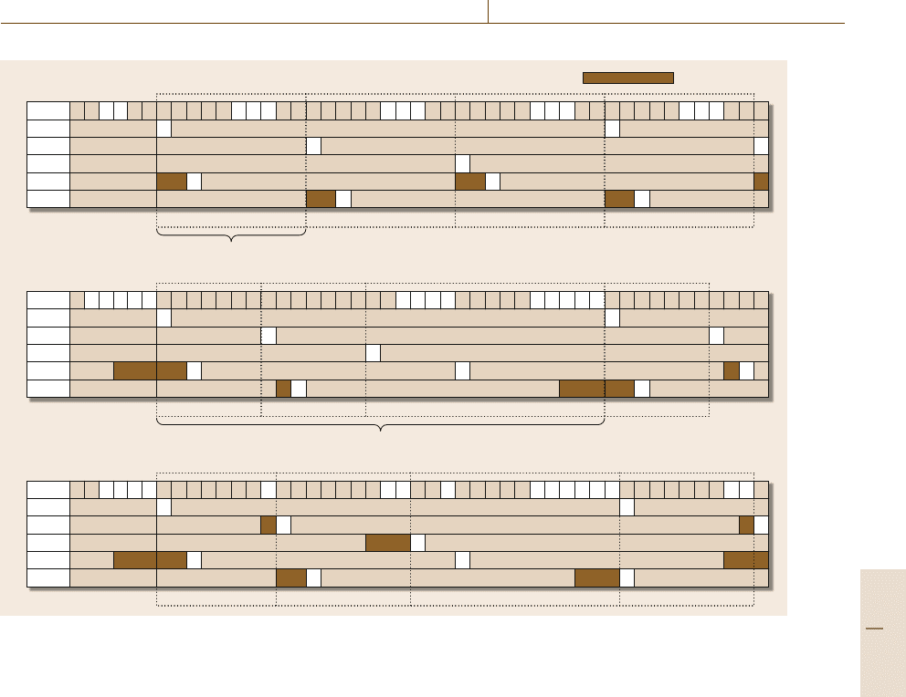
A periodic schedule repeats an identical timing pattern
for each d work cycles. When d =1, the schedule is
called steady. In a steady schedule, task delays such
as wafer delays are all constant. In a d-periodic sched-
ule, the wafer delays have d different values, while
the average is the same as that of a steady sched-
ule. The period d is determined from the TEG model.
A schedule that starts each task as soon as the pre-
Part F 52.3
Semiconductor Manufacturing Automation 52.3 Equipment Integration Architecture and Control 917
Robot
PM1
PM2
PM3
PM4
PM5
vr
τ
1
τ
2
τ
1
τ
1
τ
2
u vsvsvr u v
τ
1
τ
2
svsvr u v
τ
1
τ
2
svsvr u v
τ
1
τ
1
τ
2
τ
2
svsvr u vs
a)
Waver delay
Periodicity = 1
rr + 1 r + 2 r + 3
Robot
PM1
PM2
PM3
PM4
PM5
v
τ
1
τ
2
τ
1
τ
1
τ
1
τ
2
svsvru vsvs
τ
1
τ
2
vru vsv
τ
1
τ
2
svrvr
τ
1
τ
1
τ
2
τ
2
τ
2
svsvru vsvsv
b)
Periodicity = 3
rr + 1 r + 2 r + 3
Robot
PM1
PM2
PM3
PM4
PM5
u v
τ
1
τ
2
τ
1
τ
1
τ
2
svsvru vsv
τ
1
τ
2
svru vvs
τ
1
τ
2
svru v
τ
1
τ
1
τ
2
τ
2
svsv urv s
c)
rr + 1 r + 2 r + 3
Fig. 52.6a–c Examples of schedules. (a) Steady schedule: a SESS, (b) 3-periodic schedule, (c) irregular schedule
ceding ones complete is called earliest. An earliest
schedule can be generated by the earliest firing rule of
the TEG model that fires each transition as soon as it
is enabled. In other words, an earliest starting sched-
ule need not be generated and stored in advance. The
TEG model with the earliest firing rule can be used as
a real-time scheduler or controller for the tool. There-
fore, an earliest schedule can be implemented by an
event-based control, which initiates a task when an ap-
propriate event, for instance, a task completion, occurs.
Therefore, an earliest starting schedule based on such
event-based control has merits. First, potential logical
errors due to message sequence changes can be pre-
vented. When a tool is controlled by a predetermined
timing schedule, communication or computing delays
may cause a change in a message sequence and a criti-
cal logical error; for instance, a robot may try to unload
a wafer at a chamber before processing at the cham-
ber has been completed and hence when the wafer slot
is still closed. Second, the earliest schedule minimizes
the average tool cycle time, which is the same as the
maximum circuit ratio of the TEG model. Therefore,
the most desirable schedule is a steady and earliest
starting schedule (SESS). For a cluster tool with cyclic
operation, there always exists a SESS. Figure 52.6ais
an example of SESS for the TEG model. A SESS can
be computed in advance using the max-plus algebra
or a kind of longest-path algorithm [52.9] and imple-
mented by an event-based controller based on the TEG
model [52.10,13].
Controlling Wafer Delays
When a tool has a strict constraint on the maximum
wafer delay, as in low-pressure chemical vapor deposi-
tion, coating processes or chemical cleaning processes,
it is important to know whether there exists a feasi-
ble schedule that satisfies the constraint. There have
been works on the schedulability of a cluster tool,
that is, the existence of a feasible SESS [52.11, 14].
Lee and Park [52.14] propose a necessary and suffi-
cient condition for schedulability, that is, the existence
of a feasible SESS, based on circuits in an extended
Part F 52.3

918 Part F Industrial Automation
version of TEG called negative event graph, which
models the time-window constraints on wafer delays
by negative places and tokens. In fact, schedulability
can also be verified by the existence of a feasible so-
lution in an associated linear program. However, the
necessary sufficient condition identifies why the time
constraints are violated, and often gives a closed-form
schedulability condition based on the scheduling pa-
rameters such as the process times, the robot task times,
and the number of parallel chambers for each process
step.
Most schedulability analyses assume deterministic
process and task times. When a cluster tool is oper-
ated by a SESS, the wafer delays are kept constant.
However, in reality, there can be sporadic random dis-
ruptions such as wafer alignment failures and retrials
or exceptional process times. In this case, the sched-
ule is disturbed to a non-SESS, in which the wafer
delays fluctuate and may exceed the specified limits.
However, there are regulating methods that quickly re-
store a disrupted schedule. Kim and Lee [52.15]propose
a schedule stability condition for which a disrupted ear-
liest firing schedule of a TEG or a cluster tool converges
to the original SESS regardless of the disruptions, and
a simple way of enforcing such stability by adding an
appropriate delay to some selected tasks. Therefore, we
can regulate wafer delays to be constant. Such a sta-
bility control method has been proven to be effective
even when there are persistent time variations of a few
percent [52.15]. Even when the process times or the
robot task times vary significantly, but only if they are
within a bounded range, schedulability against wafer
delay constraints can be verified by an efficient algo-
rithm on an associated graph [52.15]. When the initial
timings are not appropriately controlled or a SESS is
disrupted, the earliest schedule converges to a periodic
schedule whose period is determined from the TEG.
Therefore, the wafer delays can be much larger than the
constant value for a SESS. For a given wafer delay con-
straint, even if the schedulability condition is satisfied,
that is, a feasible SESS exists, a periodic schedule may
have wafer delays that exceed the limit. Therefore, we
are concerned with whether such a periodic schedule
with fluctuating wafer delays can satisfy the wafer de-
lay constraint. Lee et al. [52.10] proposed a systematic
method for identifying exact values of task delays of
a TEG or wafer delays of a cluster tool for each type
of schedule: steady or periodic, earliest or not. From
the method, the schedulability of periodic schedules,
which occurs when timings are not well controlled, can
be verified.
Workload Balancing for Tools
In a traditional flow line or shop, the workload of a pro-
cess step is the sum of the process times of all jobs
for the step. The bottleneck is the process step with the
maximum workload. Imbalance in the workloads of the
process steps causes waiting of jobs or work in progress
before the bottleneck. However, in automated manufac-
turing systems such as cluster tools, the workload is
not easy to define because the material-handling system
interferes with the job processing cycle. To generalize
the workload definition, we can define the generalized
workload for a resource as the circuit ratio for the cir-
cuit in the TEG that corresponds to the work cycle of
the resource [52.10,16]; for instance, the workload for
a chamber at process step i with m
i
parallel chambers in
a single-armed tool is (p
i
+2l+2u +3v)/m
i
, because
each work cycle of a chamber requires a wafer process-
ing (p
i
), two loading tasks (2l), two unloading tasks
(2u), and three robot moves (3v). A robot has work-
load (n+1)(u +l +2v), the sum of all robot task times.
Therefore, the overall tool cycle time is determined by
the bottleneck resource as
max
max
k=1,2,...,n
p
k
+2l+2u +3v
m
k
,
(n +1)(u +l +2v)
.
Imbalance between the workloads or circuit ratios
causes task delays such as wafer delays. In a single-
armed tool, the workload imbalance between process
step i’s cycle and the whole tool cycle is
max
max
k=1,2,...,n
p
k
+2l+2u +3v
m
k
,
(n +1)(u +l +2v)
−
(p
i
+2l+2u +3v)
m
i
.
Notice that each chamber at process step i has cycle
time (p
i
+2l+2u +3v), while the overall cycle time
at the process step is (p
i
+2l+2u +3v)/m
i
. Therefore,
the delay in each cycle of a chamber at process step i
is m
i
times as long as the workload imbalance at the
process step. Consequently, the average wafer delay at
a chamber at process step i is [52.10]
m
i
max
max
k=1,2,...,n
p
k
+2l+2u +3v
m
k
,
(n +1)(u +l +2v)
−(p
i
+2l+2u +3v) .
We note from the well-known queueing formula, Lit-
tle’s law, that the average delay is proportional to the
Part F 52.3

Semiconductor Manufacturing Automation 52.3 Equipment Integration Architecture and Control 919
average work in progress. In a cluster tool, wafer de-
lays are more important than the number of waiting
wafers because of extreme limitation on the wafer wait-
ing space. Wafer delays can be reduced or eliminated
by balancing the circuit ratios. Such generalized work-
load balancing can be doneby addingparallel chambers
to a bottleneck process step, accommodating the pro-
cess times within technologically feasible ranges or
intentionally delaying some robot tasks [52.10,16]. Lee
et al. [52.10,16] proposed a linear programming model
that optimizes such workload balancing decisions un-
der given restrictions. Workload balancing is essential
for cluster tool engineering.
Additional Works
Cluster toolswith cleaningcycles, multi-slots, and reen-
trance present more challenging scheduling problems.
There are some works on using cyclic scheduling for
these problems [52.4, 17,18]. For a tool controlled by
a dispatching rule, we cannot optimize the rule and
identify or control wafer delays. Wafer delays are un-
expected and can be excessively long. Nonetheless,
dispatching rules are inevitable when the scheduling
problem is too complex or involves uncontrollable sig-
nificant uncertainty. Reentrance, cleaning cycles, and
multi-slots contribute significantly to scheduling com-
plexity. In general, process times and robot task times
in cluster tools and track equipment are relatively
well regulated and have variations within a few per-
cent, because most processes are designed to terminate
within a specified time. However, modern adaptive
process control that adapts process control parame-
ters based on real-time sensor information may cause
significant time variation. Cleaning based on cham-
ber conditions may occur randomly and hence increase
uncertainty significantly. There are some works on
dispatching rules for cluster tools with cleaning and
multi-slots [52.19].
52.3.3 Control Software Architecture,
Design, and Development
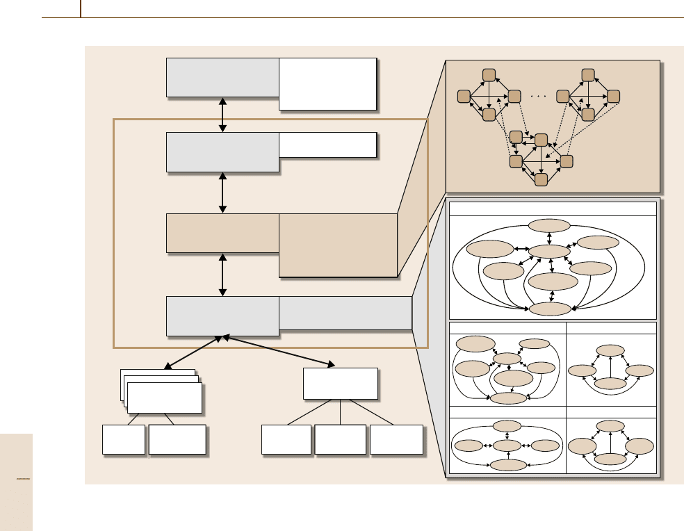
In a cluster tool, each processing module or chamber
is controlled by a process module controller (PMC).
The robot, loadlocks, and slot valves at the chamber
are controlled by a transport module controller (TMC).
A module controller receives data from the sensors in
a chamber, and issues control commands to the ac-
tuators such as gas valves, pumps, and heaters. The
module controllers use bus-type control networks called
fieldbuses such as process field bus–decentralized pe-
ripherals (PROFIBUS-DP) and control area networks
(CANs) for communication and control with sensors
and actuators. The module controllers are also coor-
dinated by a system controller, called the cluster tool
controller (CTC). A CTC has a module manager and
a real-time scheduler. A module manager receives es-
sential event messages from the PMCs, manages the
states of the process modules, and sends the PMCs
detailed control commands to perform a scheduling
command from the scheduler. Communication between
the PMCs, TMC,andtheCTC usually uses transmis-
sion control protocol/Internet protocol (TCP/IP) based
on Ethernet because they are well-known and accepted
universal standards.
A real-time scheduler monitors the key events from
each PMC and the TMC through the module man-
ager. The events include starts and completions of
wafer processing or robot tasks, which are essential for
scheduling. Then, the scheduler determines the states of
the modules and scheduling decisions as specified by
the scheduling logic or rules, and issues the schedul-
ing commands to the module manager. Since the wafer
flow pattern can change, the scheduling logic should be
easily changed without much programming work. The
modules are often configured by a tool vendor to fulfill
a specific cluster tool order. For large liquid-crystal dis-
play (LCD) fabrication, the modulesare often integrated
at a fab to assemble alarge-scale cluster tool. Therefore,
the scheduler should implement the scheduling logic
in a modular way for flexibility when changing logic.
To do this, the scheduling logic can be implemented
by an extended finite state machine (EFSM) [52.13].
An EFSM models state change of each module and
embeds a short programming code for the scheduling
logic or procedure. The scheduling logic also includes
procedures for handling exceptions such as wafer align-
ment failures, processing chamber failures, robot arm
failures, etc. Figure 52.7 illustrates a typical architec-
ture for communication and control in a cluster tool.
A tracksystem has a similar communication and control
architecture.
A SEMI standard, cluster tool module commu-
nication (CTMC), specifies a model of distributed
application objects for module controllers and a CTC,
and a messaging standard between the objects [52.20].
Lee et al. [52.21] also propose an object-oriented ap-
plication integration framework based on a high-level
fieldbus communication protocol and service standard,
PROFIBUS-field message specification (FMS), which
defines a messaging standard between manufacturing
equipment based on their object models. They sug-
Part F 52.3
920 Part F Industrial Automation
Job edit
Receipe edit
Alarm manipulation
IO value setting
Complete-
wafer
Complete-
wafer
Ready
Disabled
Disabled
Disabled
Clean
Process
Prepare
Prepare-
wafer
Prepare-
chamber
Prepare-
chamber
Prepare-
wafer
Robot FSM
Process module
PM2 FSMPM1 FSM
User interface
Job manipulation
Task command scheduling
Exceptional handling
Event reporting
Exceptional handling
Scheduler
PMC
TMC
Mechanical
Events/
messages
Slot valveLoadlock Robot armProcess
Lot manipulation
Lot controller
MC level task decomposition
MC coordination
Module manager
CTC
Unload
Ready
Prepare
Ready PlacePick
Load
ClosedOpen
Ready
Disabled
Pump-
up
Pump-
down
Ready
Disabled
Loadlock
Robot arm
Slot valve
Chuck
Fig. 52.7 A cluster tool controller architecture [52.22]
gest that some object models in CTMC, which were
defined based on a traditional object model for material-
handling systems, need to be modified to handle the
robot tasks in a cluster tool.
Each time a new cluster tool is developed, the
scheduling logic and a CTC application should be in-
tegrated and extensively tested. However, tool testing
and verification involve difficulties. First, a real tool is
expensiveand hence cannotbe tied upfor extensive test-
ing. Second, testing with a real tool can be hazardous
due to mechanical or space restrictions. Third, since the
dynamics of a real cluster tool is slow, it takes signifi-
cant time to test the system. Finally, it is often difficult
to recognize subtle logical errors by observing opera-
tional behavior of a real tool. Therefore, the CTC and
scheduler need to be tested in a virtual environment
such as a virtual cluster tool (VCT), in which the pro-
cess modules and the transport modules are replaced by
their emulators [52.22]. The emulators receive control
commands from the scheduler through the module man-
ager and/or the module controllers, and create messages
for events such as process completions or robot task
completions at appropriate times. The process times can
be accelerated for initial rough-cut testing. Tool engi-
neers examine the sequence of the events generated at
the CTC or module controllers, and detect an anomaly.
Such verification takes several days or weeks and is te-
dious. Some errors are hard to recognize and are often
missed. Joo and Lee [52.22] propose the use of event
sequence finite statemachines for automaticerror detec-
tion, which is basically identicalto a finite state machine
except that, when an event other than allowed ones at
a state occurs, an error is assumed. They detected sev-
eral unexpected logical errors, including logical errors
caused by message sequence changes due to communi-
cation delay. Most tool simulators, such as ToolSim by
Brooks Automation, focus on performance evaluation
of a configured tool rather than high-fidelity model-
ing and verification of tool operation and messaging
between a CTC and module controllers.
Part F 52.3
Semiconductor Manufacturing Automation 52.4 Fab Integration Architectures and Operation 921
52.4 Fab Integration Architectures and Operation
52.4.1 Fab Architecture and Automated
Material-Handling Systems
In modern 300mm fabs, wafer cassette-handling tasks
for interbay moves as well as intrabay ones are au-
tomated. In order to save the footprint and secure
human operator access for equipment maintenance or
exception handling, overhead transport (OHT) systems
are mostly used. Traditional automated guided vehicle
(AGV) or rail-guided vehicle (RGV) systems have been
replaced by OHTs. In order to reduce particle contam-
ination risk, tasks of loading and unloading wafer at
tools are automated by using a new wafer carrier, the
front open unified pod (FOUP), and a standard me-
chanical interface (SMIF). Processing tools are often
enclosed in a minienvironment with extreme cleanness.
Design and operation of the architecture and AMHSs
of such fully automated fabs should be optimized to
maximize throughput and reduce the cycle time while
minimizing capital investment. An AMHS itself can
be a bottleneck due to a limited number of vehicles
and congestion on transport rails. Transport routes are
not so flexible and should be considered as a limited
resource. Therefore, in some 300mm fabs, even crit-
ical metrology steps are skipped in order to reduce
excessive vehicle traffic and the cycle time. Schedul-
ing and dispatching systems are not yet well designed
to handle such fully automated fabs. Control software
such as manufacturing execution systems (MESs), ma-
terial control systems (MCSs), equipment controllers,
and schedulers as well as the AMHS architecture are
Stocker
Empty
OHT
Loaded
OHT
Equipment
Interbay
loop
Intrabay
loop
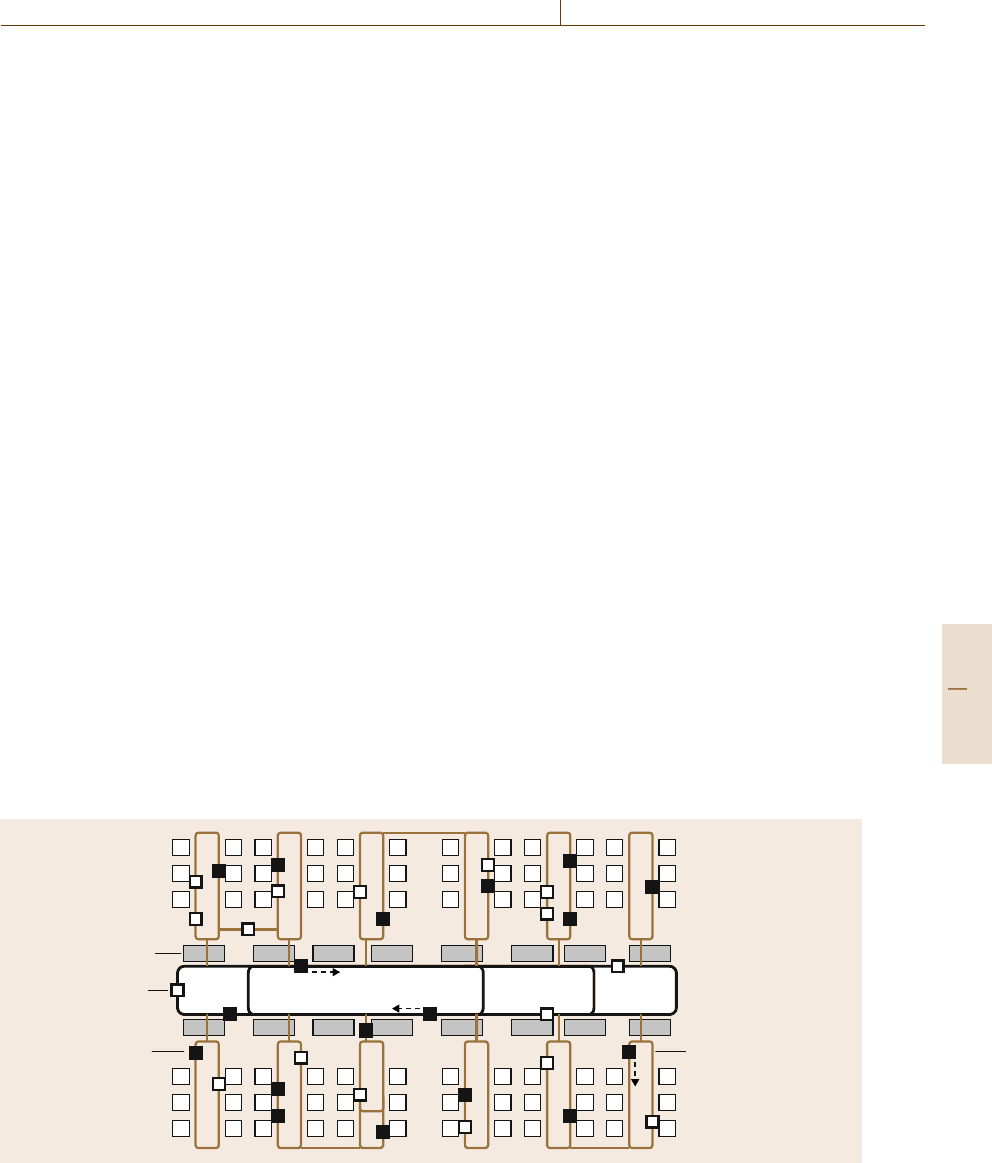
Fig. 52.8 An overhead transport system
not yet as intelligent and flexible as human operators,
who make adaptive and intelligent decisions depending
on the situation. There still remain many challenges to
smart and efficient fully automated fabs. Figure 52.8 il-
lustrates a typical OHT system layout, which consists
of intrabay and interbay loops. There are works on opti-
mal design of OHT networks, optimal number of OHTs,
and performance analysis [52.23,24].
Automated material-handling systems mostly have
limited handling capacity and flexibility due to re-
stricted paths and limited number of vehicles. There-
fore, stockers or waiting places have been mandatory
solutions for such problems. Stocking wafer cassettes
at a bay involves significant delay due to prior wait-
ing cassettes and handling operations. Therefore, in
some 300mm fabs, a desire to minimize the deliv-
ery cycle time led to attempts to combine several bays
into a larger cell by eliminating bay-stockers in or-
der to enforce direct delivery. However, this may cause
significant OHT congestion and blocking, and hence
throughput degradation. Nonetheless, direct delivery
is one of the key technological challenges for next-
generation 450mm fabs [52.25]. To achieve the goal of
direct delivery, we need quite different architectures of
fabs and material-transfer systems. A solution might be
to mimic a transfer line or a conveyor system, where
wafer cassettes go through a significant number of pro-
cess tools without intermediate stocking. Such a system
is called aninline system. Oneof themost seriousdisad-
vantages of inline systems is lack of flexibility. In future
fabs, lot sizes will continue to shrink. Therefore, con-
Part F 52.4
922 Part F Industrial Automation
flicting goals of flexibility and direct delivery should
be resolved. LCD fabs, for which material transfer has
been fullyautomated from the early stage due to manual
handling difficulties, tend to introduce inline systems
for more process steps as the panel size increases con-
tinually. A future 450mm fab may also resemble an
LCD line [52.25]. Stocker racks may be extensively lo-
cated in parallel to the inline system [52.25]. Several
alternatives for future fab and material-handling system
architectures are now being discussed [52.26].
Traditionally, AMHSs have been scheduled and
controlled separately from job scheduling. That is,
wafer processing jobs are scheduled disregarding the
limited capacity of the AMHS, and then material-
transfer tasks, which are requested from the job
schedule executor such as a real-time dispatcher, are
separately planned and controlled by a material control
system (MCS), that is, the AMHS controller. However,
such decoupling is not so effective for modern inte-
grated systems where job scheduling is significantly
restricted by the AMHS, and vice versa. Interaction be-
tween job schedulesand material transfercontrol should
be considered, or they should be simultaneously sched-
uled as in cluster tools. MCSs have been engineered
by AMHS vendors and are managed by automation
engineers in fabs. However, job scheduling has been
done by production management or control staffs. In
the future, the two staff groups should better collabo-
rate to tightly couple job scheduling and AMHS control.
As fab technologies evolve, material-handling require-
ments become more challenging. SEMI has updated
a roadmap for AMHSs for future fabs [52.27].
ERP
MES
Cell/system controller
Equipment controllerEquipment controller
MMI (man–machine
interface)
Control
logic
HW
drivers
GEM
SECS-II
HSMS
(TCP/IP)
MMI (man–machine
interface)
Control
logic
HW
drivers
GEM
SECS-II
SECS-I
(RS232)
UI (user interface)
Cell control logic
VFEI (virtual
factory equipment
interfaces)
MES
lib-
rary
SECS-II
HSMS
(TCP/IP)
SECS-I
(RS232)
Open object interface framework
(CORBA/DCOM/OPC-based application object interface)
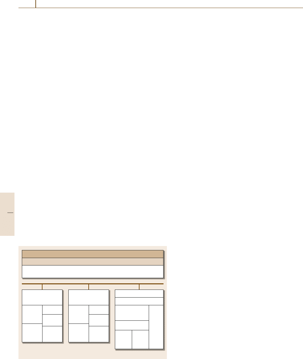
Fig. 52.9 Communication architecture for fab automation
52.4.2 Communication Architecture
and Networking
SEMI communication standards have been widely used
in fabs to reduce system integration efforts [52.28].
While old tools are connected only by RS-232 ports,
modern tools have Ethernet connections. The semicon-
ductor equipment communication standard I (SECS-I)
and high-speed message standard (HSMS) define data
standards on RS-232-based serial communication and
TCP/IP communication over Ethernet connection, re-
spectively. SECS-II defines messaging standards. The
generic equipment model (GEM) and virtual factory
equipment interfaces (VFEI) are object-based appli-
cation interface standards for equipments and factory
control applications, respectively. The overall com-
munication architecture is summarized in Fig.52.9.
AMHSs use fieldbus or control networks, either open
or proprietary.
As advanced process control (APC) technology for
real-time process sensing and real-time adaptive con-
trol becomes widespread, there is increasing demand
on high-speed real-time communication technology, be-
yond the current communication architecture, in order
to process massive process sensing data in real time.
52.4.3 Fab Control Application Integration
The most critical application for factory integration
is a manufacturing execution system (MES). Its ba-
sic functions are to monitor equipment, send recipes,
and keep track of wafers or other auxiliary materials
such as photomasks. Quality monitoring and scheduling
functions tend to be performed by separate appli-
cations from specialized vendors. MES applications
should be easily and reliably integrated with equip-
ment control applications. Traditionally, MESsused
middleware based on message queueing to reliably
process massive event messages from many equip-
ments. No messages should be lost and the response
time should be controlled. Therefore, such messages
from many different tools are queued and the mes-
sage queues are served by reasonable queueing or
service policies for load balancing and response time
control. Such message-based communication and inte-
gration require significant application work to integrate
MES applications with equipment control applica-
tions. An application designer should understand all
low-level messages and their required sequence for
logical interaction between the MES and equipment
controllers. Debugging, verification, and modification
Part F 52.4
Semiconductor Manufacturing Automation 52.4 Fab Integration Architectures and Operation 923
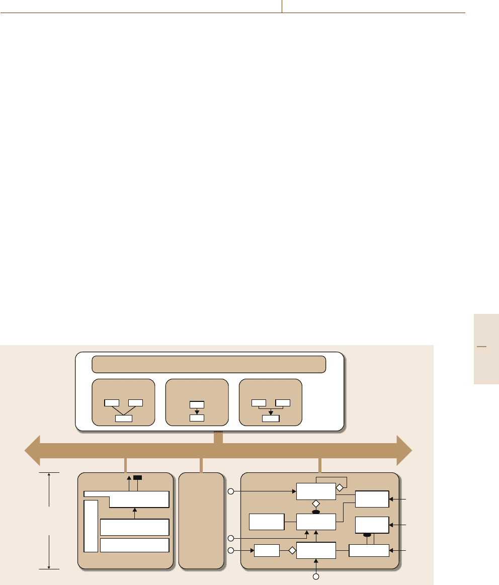
are not easy. An alternative approach is object-
based application integration. Each equipment and an
MES application have a model of constituent ob-
jects, which specify the functions and informational
states. Then, interactions between an MES and equip-
ment are implemented by method calls or service
requests between their corresponding objects. The com-
mon object request broker architecture (CORBA)is
a middleware solution for facilitating application inte-
gration and interaction between such distributed objects
and managing objects and services. MES application
designers can conveniently make use of the high-
level services of the objects in equipment control
applications as well as common MES application ob-
jects. Detailed messaging sequences are handled by
the methods of the objects that provide the relevant
services. SEMI proposed an object-based MES appli-
cation design standard, called the computer-integrated
manufacturing (CIM) framework. SEMI also devel-
oped a standard object model for control applications
of process equipment, called the object-based equip-
ment model (OBEM). There have been concerns about
whether CORBA can work reliably and fast enough
for modern fab environments that generate massive
amounts of real-time data. However, MES vendors
have successfully implemented CORBA-based MES
solutions, for example, IBM’s SiView and AIM Sys-
Application components/objects
CORBA
OBEMOBEM
MES
Basic components/
objects
...
OBEM
(Object
based
equipment
model)
Machine
module
Machine
port
Machine
Equipment
control
applications
Equipment
resource
Equipment
resource
Part
location
Material
location
Process
capability
OBEM/CORBA
Intermediate
components
Physical equipment
User interface
Equipment
resource
Clock Carrier part
Fig. 52.10 Object-based interaction for MES and equipment control applications
tem’s NanoMES. Figure 52.10 illustrates object-based
interaction.
Recently, the service-oriented architecture (SOA)
has been increasingly popular for business and enter-
prise applications [52.29]. Business processes tend to
change frequently to cope with business requirement
changes, and to be distributed over the Internet. There-
fore, more flexibly composable services are defined and
called as needed to form a new business process. Ob-
jects are considered to have too small granularity to
be used for business processes [52.29]. Further, dis-
tributed objects technology such as CORBA and the
distributed component object model (DCOM) are not
easy standards to work with, because it is difficult to
integrate object applications that were developed by
different people at different places on different plat-
forms at different times. Furthermore, CORBA and
DCOM are not widely understood by software en-
gineers and control and automation engineers. Web
services have been open standards for easily integrating
applications distributed on the Internetby using extensi-
ble markuplanguage (XML)-based open standardssuch
as simple object access protocol (SOAP), web services
description languages (WSDLs), and universal descrip-
tion, discovery, and integration (UDDI), and standard
web protocols such as XML, hypertext transfer proto-
col (HTTP), and transmission control protocol/Internet
Part F 52.4
924 Part F Industrial Automation
protocol (TCP/IP). Therefore, SOA based on web ser-
vices can provide open standards for easily integrating
distributed factory applications with proper granular-
ity. Therefore, some fabs or vendors for MESsor
fab management applications are also now considering
SOA-based design. However, it should be studied more
whether SOA really makes sense for factory applica-
tions in terms of reliability and real-time performance.
52.4.4 Fab Control and Management
Fab operation is highly complicated due to the com-
plex process steps and the massive number of lots in
progress. One of the most crucial fab control applica-
tions is a real-time dispatcher that keeps track of the
lots and equipment states, and determines which lots
will be processed at which tools. It uses dispatching
or scheduling rules that are proven to be effective for
fab operation. The rules may be developed and tested
for each fab through extensive simulation in advance.
The essential function of a dispatcher is to process mas-
sive amounts of job and equipment data reliably and
quickly, and compute a dispatch list quickly. A dis-
patcher sends a scheduling command to the MCS and
the process equipment directly in an automated fab,
whereas in a manual fab human operators perform the
job of loading tasks as specified in the dispatch list.
ERP
Demand planning
Production planning
Scheduler/dispatcher
Equipment management
system
(EEES, e-Diagnostics, ...)
Quality/yield
management system
(SPC, APC, ...)
MES
(Manufacturing execution system)
– WIP tracking, equipment monitoring, command/control
Middleware
– Transaction processing, event handling, recovery
Order promising/
order management
Master planning
Integrated
equipment
controller
Equipment
controller
AMHS
controller
Communi-
cation
network
APS system
(Advanced planning & scheduling)
Factory
operating
system
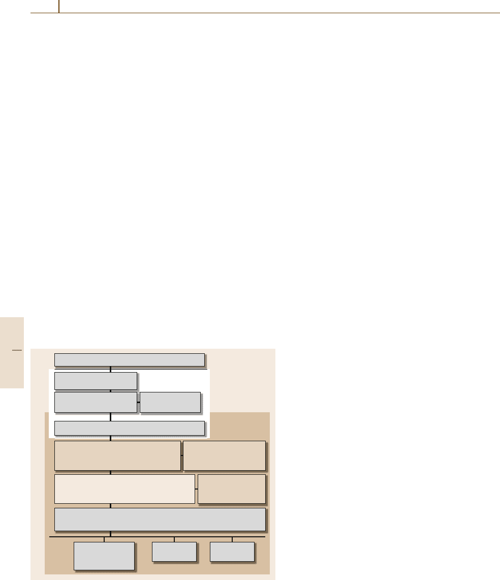
Fig. 52.11 A fab control system architecture (EEES – engineering
equity extension service, SPC – statistical process control)
An alternative scheduling approach to the dispatch-
ing rules is to have a separate scheduler that determines
an appropriate work-in-progress level for each process
step by using a dynamic lot flow model and then de-
termines an optimal schedule for each process step
separately under the restriction of the ready times and
the due dates that are imposed by the schedule of other
process steps. Frequent rescheduling is needed to cope
with changes in fabs. Even in this case, the dispatcher
retains the basic functions except for the scheduling
function, and may change the schedule from the sched-
uler by local rules depending on the fab state. This
approach has potential for further improving fab per-
formance. However, there should be more experimental
studies on whichapproach ismore effective fordifferent
fab management environments.
A production planning system or supply-chain plan-
ning system determines daily production requirements
for key process stages to meet order due dates or de-
mand forecasts while minimizing inventory level. The
system also considers binning due to random yields
and capacity constraints. Other important fab control
applications include yield management systems and ad-
vanced planning and scheduling (APS) systems. An
overall fab control application architecture is summa-
rized in Fig.52.11.
In spite of extensive literature on fab scheduling,
control, and management, there still remain many is-
sues, including how the dispatching and scheduling
systems, and scheduling rules should be developed
to fulfill complex scheduling requirements for fully
automated 300mm fabs or future 450mm fabs, in
which AMHSs will be more strongly coupled with job
scheduling for direct delivery, and lot definition and job
flows will change significantly.
52.4.5 Other Fab Automation Technologies
Fab automation aims at an autonomous factory that re-
liably and intelligently produces high-quality wafers.
As quality requirements have become stricter and
the cost of attaining this quality has increased, fabs
have developed quality-sensitive automation technolo-
gies. Advanced process control (APC) technology
includes fault detection and classification (FDC) and
run-to-run (R2R) control [52.30]. FDC makes use
of statistical methods such as multivariate analysis,
or intelligent computing or data-mining technologies
such as neural networks or rules, in order to de-
tect early any anomaly in process control that will
cause significant quality problems, classify the prob-
Part F 52.4
