Nof S.Y. Springer Handbook of Automation
Подождите немного. Документ загружается.


Aircraft Manufacturing and Assembly 51.2 Automated Part Fabrication Systems: Examples 895
goes to the flight ramp for final customer acceptance
checks and delivery.
Aircraft manufacturing techniques are well devel-
oped fabrication and assembly processes that follow
a defined sequence, and process parameters for manual
and mechanized/automated manufacturing are precisely
controlled. Process steps are inspected and documented
to meet the established Federal Aviation Administra-
tion quality requirements, ensuring reliable functions
of components, structures, and systems, which result in
dependable aircraft performance.
All activities at aircraft factories are organized
around flow of materials, parts, and structures to the
final assembly line. In the early stages of aircraft
manufacturing, detail parts are fabricated (involving
machining, heat treatment, stretch forming, superplastic
forming, chemical treatment, composite material layup,
curing, trimming, etc.), followed by part inspection
(x-ray, ultrasonic, etc.). The next manufacturing steps
focus on the assembly of detail parts into subassemblies
and larger structures using both manual assembly tasks
and automated machinery (C-frame, ring riveters, etc.),
and also moving lines for final aircraft assembly.
Due to economic pressures and ergonomic neces-
sities, the majority of manual aircraft manufacturing
has been replaced during past decades by mechanized
and/or automated processes and systems, yielding sig-
nificant process and cost saving improvements; for
example, the productivity of machining processes has
generally improved by a factor of ten, with some highly
automated assembly processes enjoying improvements
in excess of a factor of 15.
51.2 Automated Part Fabrication Systems: Examples
Automated aircraft part fabrication involves a variety
of manufacturing techniques and systems, all tailored
to processing specific materials and part configura-
tions, ranging from aluminum and titanium alloys to
carbon-fiber epoxy materials, using intelligent automa-
tion to produce strong, lightweight parts at afford-
able/competitive costs.
51.2.1 N/C Machining
of Metallic Components
Process Description
Since the advent of metallic airframe construction,
airplane manufacture has been machining intensive,
largely because the starting material forms (i.e., plate,
extrusion, die forging, etc.) were not available in near-
net shapes. To minimize airplane fly-weight and ensure
good fatigue life, most metallic surfaces are machined
to obtain the final component configuration and achieve
a specified surface finish. An important expression in
the aerospace machining industry is the buy-to-fly ra-
tio, whichindicates the ratio of excess materialremoved
during a given machining operation versus the remain-
ing material that flies away on the airplane. For an
average commercial aircraft N/C-machined part, this
ratio is about 8 :1.
The machining process usually employs a cutter
mounted in a rotating spindle, where the spindle or part
can be moved relative to one another by a numerical
controller (N/C) using servo motors. The spindle revo-
lutions per minute (RPM) may vary from 0 to 40000,
depending on the material, with the largest wing skin
mills employing multiple spindles with power ratings
up to 200 horsepower (HP). N/C machine tools com-
monly used within the aerospace industry are some
of the largest machine tools in the world, with skin
mill bed sizes ranging up to 24 ft wide by 270ft
long [51.4–8].
Wing Skin Mills
The wing skin mill shown in Fig.51.2 is capable of ma-
chining two wing skins simultaneously. The aluminum
plate from which the wing skins are produced is held
down to the skin mill bed using a vacuum. Typically the
aerodynamic outer wing surface, known as the outside
mold line (OML), is machined first. Once completed,
the wing skin is flipped over, the vacuum is reapplied,
and machining on the inside mold line (IML)iscom-
pleted. The IML contains pads and other features which
mate to other wing structure components such as wing
ribs and stringers. In addition, the wing skins, which
are thickest near the fuselage, taper down to approxi-
mately 0.25in thick at the outboard wing tip. Thickness
tolerances for these flight critical components are typ-
ically held to ±0.005in Mammoth gantries (weighing
nearly 30 t) carrying two 200HP machining spindles
over a wing skin move with precision, while holding
the necessary tolerances. Face mill cutters up to 1ft in
diameter are employed to quickly cover the vast ex-
panse of the wing skins, generating a large volume of
Part F 51.2
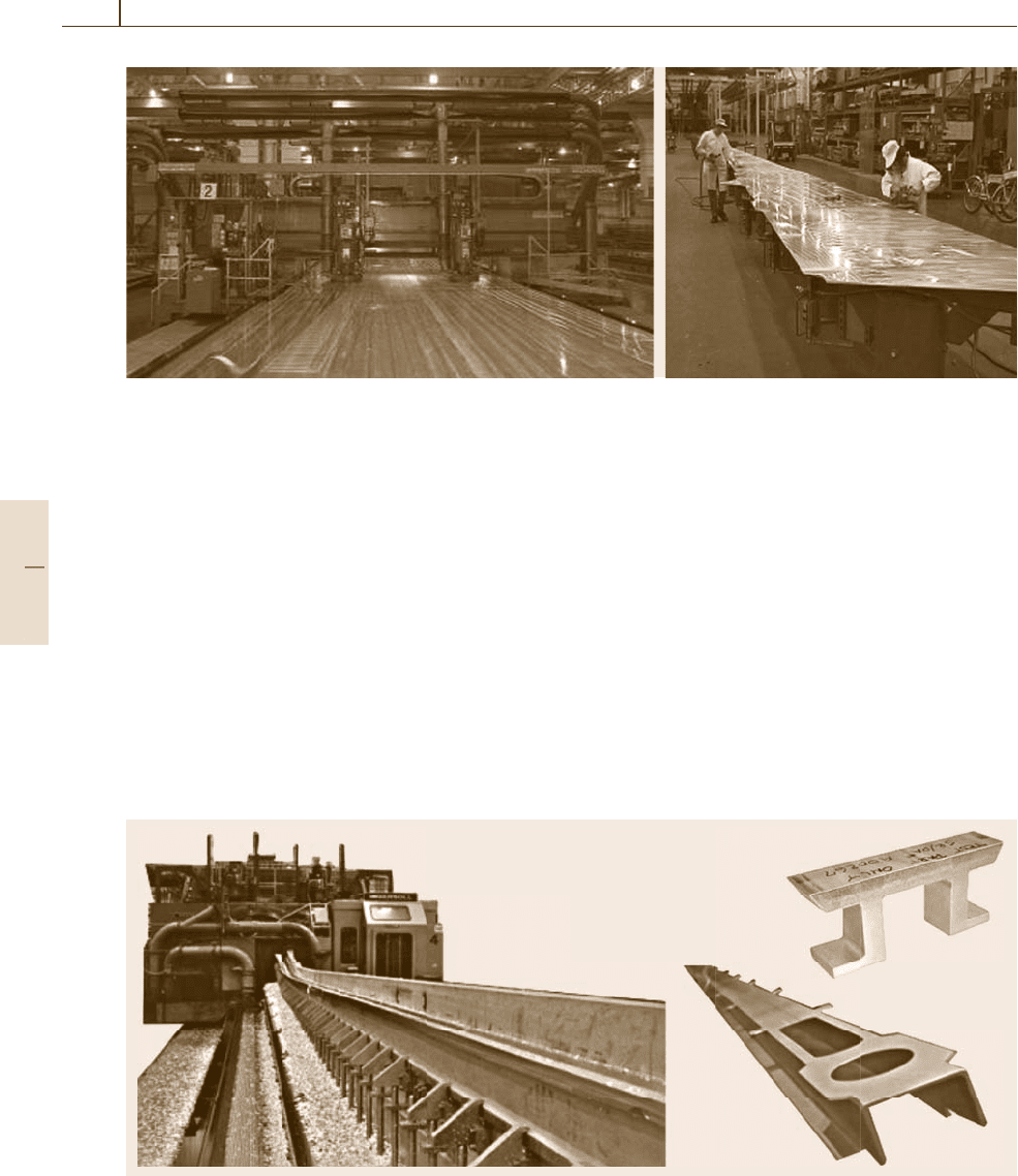
896 Part F Industrial Automation
Fig. 51.2 Cincinnati milacron wing skin mill and wing skin after machining
aluminum chips, which are collected by a vacuum chip
collection system requiring a 100HP motor.
Customized Long-Bed Gantry-Style
Milling Machines
Dedicated long-bed purpose-designed gantry-style
milling machines have been the traditional choice for
machining major wing structural components (i.e.,
stringers, spar chords, and channel vents). These
machines employ multiple high-power (112kW), low-
RPM spindles, each capable of high material removal
rates (MRR). Each wing component (upper chord,
lower chord, stringers, and channel vents) for each
airplane model has a dedicated part holding fixture.
Large-diameter cutters mounted in steep-taper tool
holders experience high cutting forces and bending mo-
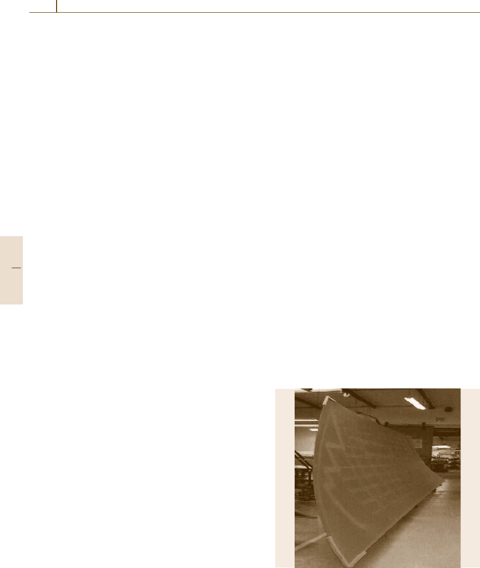
Fig. 51.3 Dedicated spar mill gantry with typical cross section and machined part
ments. This technology is still appropriate when high
MRR is required for long extruded parts of adequate
stiffness. These machines have been regarded as the
aerospace machining standard for 50years.
The right side of Fig.51.3 shows a typical 110 ft-
long completed part after machining and a typical cross
section of the extrusion that makes this part. The cross-
sectional area reduction is evident in this illustration.
Approximately 12 kg of material is machined away for
each (1 kg) of flyaway part. When buy-to-fly ratios for
various manufacturing methods are compounded by the
sheer size of commercial airplanes, it becomes obvi-
ous how an airframe manufacturer can produce over
35million pounds (16 Gg) of aluminum chips annually.
This is roughly equivalent to the airframe weight of 100
Boeing 747 aircraft.
Part F 51.2

Aircraft Manufacturing and Assembly 51.2 Automated Part Fabrication Systems: Examples 897
High-Performance Machining
As future airframe designs are considered, more em-
phasis will be placed on component producibility and
manufacturing costs. Traditional built-up assemblies
are being replaced by monolithic designs. Contrary to
popular belief, the value for the airframe producer to
utilize high-speed machining techniques does not lie
solely in reduced machining cycle times. Economies
of scale are gained not by machining cycle time re-
duction alone, but by conversion of multiple-piece
assemblies to monolithic components. This ensures
a more accurate final part and the elimination of assem-
bly tooling, labor, equipment, and facilities previously
required by built-up designs. High-performance ma-
chining provides designers a manufacturing process to
produce thin-wall monolithic parts quickly with min-
imal distortion.
However, monolithic designs are placing new bur-
dens on high-performance machining technology. Such
designs often require more material be removed dur-
ing the machining process than previously required
for built-up or assembled sheet metal components.
It is difficult to use extrusions or die forgings for
monolithic airplane components that are long with
significant cross-sectional changes. Components up to
110ft (35 m) with a tapering cross-section must either
be produced from multiple die forgings that are joined
or machined from plate stock (if they are designed
as a monolithic part). This requires removing large
amounts of material, as depicted in Fig.51.3. Increased
buy-to-fly ratios will necessitate that more emphasis
be placed on maximizing material removal rates in the
future.
Technical data
• Stretch forming of large contoured fuselage skins
• Machine size: L = 20m; W = 4m; H = 3m
• Sheet size max. t = 6mm; W = 2.5m; L = 12m
• Articulating jaws stretch force = 1500 tons
• Articulating jaws min. radius: longitudinal axis = 10m
• Articulating jaws min. radius: transverse axis = 2m
• Stretch die table max force = 1000 tons
• CNC controller
• All machine motions can be actuated manually or
controlled by program
Fig. 51.4 Stretch-forming machine for skins
51.2.2 Stretch Forming Machine
for Aluminum Skins
Machine Description
The machine depicted in Fig.51.4 is capable of stretch-
forming large contoured fuselage skins. The major
machine components are:
1. A die table for supporting and moving stretch form
dies (dies contain the configuration of the final skin
and are placed on the table) vertically during the
stretch forming process.
2. Two articulating jaws (one on each side of the
table), consisting of multiple jaw segments, en-
abling articulation of each jaw around longitudinal
and transversal axis to accommodate the contoured
skin geometry. Jaw segments have built-in hydraulic
clamps which firmly clamp the metallic sheets prior
to the stretch-forming process. During the forming
process each jaw moves longitudinally away from
the die table.
3. A computerized numerical control (CNC)ma-
chine controller, which executes stretch-forming
programs by activating/moving machine compo-
nents [51.1–3].
Heat-Treat and Stretch-Forming Processes
Common structural materials used for fuselage skins,
fuselage frames, and stringers are the high-performance
aluminum alloys, namely the2000series and 7000series
aluminum alloys (i.e., 2024, 7075). Both of these alu-
minum alloys are heat-treatable for strength, toughness,
and corrosion resistance. To achieve high strength,
Part F 51.2
898 Part F Industrial Automation
the 2024 alloy, commonly used for fuselage skins, is
heat-treated in furnaces up to 496
◦
C. A quenching
process from these elevated temperatures dissolves the
alloy constituents (i. e., such as copper) in a solid state
in the solid aluminum alloy. After quenching, room-
temperature aging occurs, causing copper constituents
to precipitate along the grain boundaries and along slip
planes of the alloy. This action distorts the crystal lat-
tice interferes with any smooth slip process, resulting
in increased strength of the material. Immediately af-
ter quenching, the material is relatively soft and can be
formed as in as-quenched (AQ) tempering. However af-
ter about 20min the alloy will start room-temperature
aging and strengthen to the T4temper condition. Room-
temperature aging is also referred to as natural aging.
The final T4 strength obtained is about 96h.
Alloy sheets are moved from the quenching sys-
tem/equipment to the stretch-forming machine and laid
up on the stretch die, then both ends of the sheets are
pushed into the jaws and jaw segment clamps are ac-
tivated, clamping onto sheet ends. Jaw segments are
configured around the longitudinal axis to accommo-
date skin shape, dictated by the stretch die geometry,
and longitudinal forces are applied to the sheet by driv-
ing jaws away from the table. At a certain point, the
table isactivated, moving thestretch die vertically while
the jaws rotate around the transversal axis, pulling the
sheet and forcing it to comply to the stretch die ge-
ometry. After sufficient stretch (plastic deformation) is
achieved, the jaws and table reverse direction, relieving
tension on the sheet once it has attained the desired skin
geometry (and allowing for some spring-back). Ideally,
aluminum skin stretch form dies are built with spring-
back compensation. This is especially important for
large contoured skins. Software for stretch die design
tools are readily available and have proven very useful.
For many decades, the stretch forming process was
(and partially still is) a black art. It requires very ex-
perienced personnel to drive machine elements (table,
jaws) in linear and rotational axes while observing the
skin during stretch-forming operations. Variations in
skin and stretching behavior result from changes in ma-
terial properties during the incubation time and make
it difficult to establish precise process parameters. Af-
ter years of experimentation, and collecting empirical
data (required degree of stretch, etc.), the majority of
skin form operations can be computer controlled or
at least semi-automated, whereby the operator observ-
ing the skin behavior can make slight adjustments to
the degree of stretch to compensate for material prop-
erty variations. Programs can be generated offline, or
recorded/stored in the teach mode on the machine dur-
ing the stretch-forming process.
51.2.3 Chemical Milling and Trimming
Systems for Aluminum Skins
System Description
Chemical milling is a material removing process using
chemical reaction to dissolve material in certain loca-
tions to produce contoured skins with variation in cross
sections (thickness), accommodating changing design
load conditions along the fuselage. This process in-
volves several subsystems:
1. Galvanic treatment tanks for cleaning and surface
preparation of stretch-formed skins
2. A five-degree-of-freedom (DOF) robotic system ap-
plying a mask to the skin surface
3. A five-DOF gantry robotic system and flexible pogo
fixture using a carbon-dioxide laser to scribe the
mask, enabling mask removal in certain skin loca-
tions
4. Chemical milling and galvanic treatment tanks to
perform metal removal (chemical milling)
5. A five-DOF CNCgantry systemwith a flexible pogo
table to trim and drill skins [51.1–3].
Process Description
Stretch-formed skins have to be cleaned and surface
prepared for the application of the chemical milling
mask. A robotic system under program control auto-
matically applies the mask of defined thickness to both
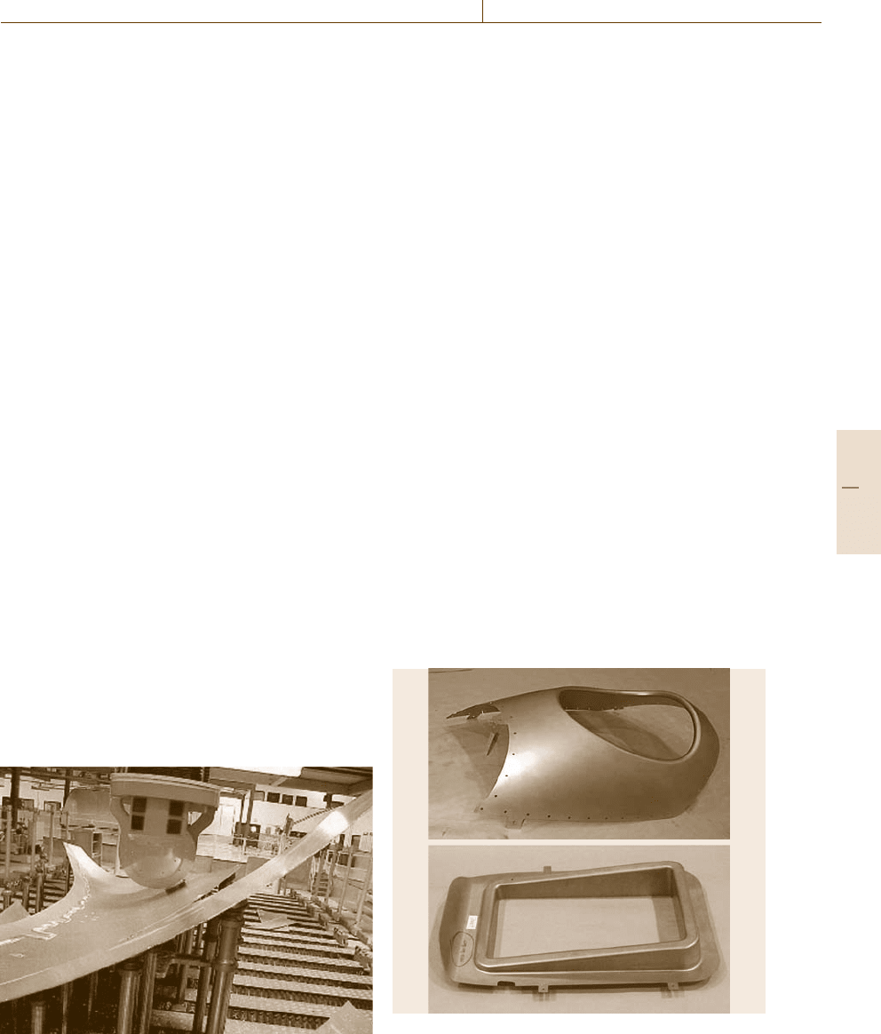
Fig. 51.5 Skin with scribed mask
Part F 51.2
Aircraft Manufacturing and Assembly 51.2 Automated Part Fabrication Systems: Examples 899
sides of the skin, moving a spray nozzle along opti-
mized patterns to achieve homogeneous mask coverage
thickness and to minimize overspray. After the mask
is sufficiently dry, skins are positioned onto the flexi-
ble pogo table, stabilized with suction cups to pogos.
The skin surface pointing to the outside of the air-
craft is positioned onto pogos and does not require any
chemical milling. A gantry robot moves the head with
a carbon-dioxide laser in five DOFs across the inner
surface of the skin, scribing (cutting) mask along cer-
tain patterns to facilitate peeling off of the mask. After
all patterns are cut (Fig.51.5) skins are processed using
computer-controlled cranes to move skins through the
chemical milling tanks. First, the mask is removed in ar-
eas which will lead to the thinnest skin cross-sections.
Skin is dipped into the chemical milling tank, allowing
NaOH chemical (kept at elevated temperatures) to etch
exposed aluminum surface long enough to achieve the
desired remaining cross section. Etching velocity de-
pends on the NaOH concentration (which is controlled
daily). The etching velocity is used as an input param-
eter to the crane controller, which pulls the skin out
of the tank at a predetermined time automatically. If
measurement of the desired aluminum skin thickness is
verified, the next mask area is peeled off, and the next
chemical milling process is repeated, until all required
skin areas are processed. The last skin processing step
involves trimming of boundaries and drilling of tool-
ing and determinant assembly holes. These tasks are
accomplished on thefive-axis trimming anddrilling ma-
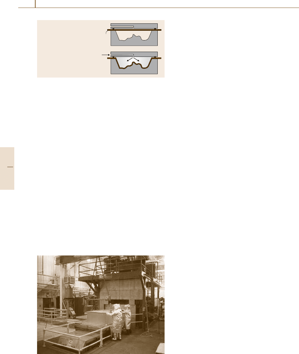
chine (Fig. 51.6). Pogosof the flexiblemachine table are
driven in three linear DOFs to positions dictated by the
skin configuration, and swiveling suction cups on top of
pogos stabilizethe skinduring thetrimming and drilling
operations. Mechanical cutters and chip extraction noz-
Fig. 51.6 CNC trimming and drilling system
zles surrounding the cutter are used. Net trimmed skins
with tooling and determinant assembly holes are now
ready for assembly.
All crane movements in the galvanic process line
and the robotic chemical mask application process are
controlled by a simple program. For mask scribing, the
laser gantry robot, and the trimming/drilling robotic
system, computer-aided design (CAD) skin geome-
try data is imported into the process simulation and
a semi-automated program creation system generates
processing programs.
51.2.4 Superplastic Forming (SPF)
and Superplastic Forming/
Diffusion Bonding (SPF/DB)
Process Description
The SPF process is an elevated-temperature process
where fine-grain material, such as alpha-beta titanium
(Ti-6Al-4V is most common) and certain aluminum
alloys (7475, 2004, and 5083), can be formed into com-
plexshapes usinggas pressure.The processtemperature
depends on the material and alloy being formed: tita-
nium (774–927
◦
C aluminum (454–510
◦
C). SPF parts,
such as those shown in Fig. 51.7, are produced with
typical elongations up to 300% [51.4–8].
The basic principles of the superplastic forming pro-
cess are illustrated in Fig.51.8, typically using heat and
gas pressure to fully form aluminum or titanium part
blanks to match the tool’s contour.
Fig. 51.7 Parts fabricated using super plastic forming
(SPF)
Part F 51.2
900 Part F Industrial Automation
• Elevated temperature
• Superplastic material
• Computer-controlled gas
pressure forms the part
into the cavity at a
constant strain rate
Part
Gas
Fig. 51.8 SPF process principles
The SPF/DB process combines an SPF operation
with a diffusion bonding (DB) process, whereby two or
more sheets of titanium are used to create an integrally
stiffened panel structure. For DB to occur, the titanium
sheets must contact each other in an inert atmosphere
at controlled temperatures and pressures for a speci-
fied time. Several methods can be used to achieve these
conditions. The one shown in Fig.51.9 uses a heated
press and tool pressure to bring the sheets together.
Another method uses gas pressure inside the welded ti-
tanium pack to force the sheets into contact with each
other. Diffusion bonding is a solid-state process and
no melting occurs at the bond line. Once the individ-
ual grains on the surface touch each other, they start
growing across the interface of the two sheets. This pro-
cess continues until the sheets are completely diffusion
bonded to each other and there is no evidence micro-
scopically of there having been two, or more, pieces of
material.
The typical hot (up to 982
◦
C) shuttle table press,
showninFig.51.9, produces SPF and SPF/DB alu-
minum and titanium parts and has computer-controlled
heating, pressure, and gas systems.
Fig. 51.9 Hot press, tool, and SPF part
SPF Benefits.
The benefits of the SPF process are that:
•
It replaces multipiece assemblies with one mono-
lithic component, saving cost, weight, and tool-
ing.
•
It can produce complex geometry and sharp radii.
•
Components contain very little, if any, residual
stress (no spring-back).
•
Less assembly is required (lower cost, lighter
weight, and better dimensional accuracy).
•
Titanium parts are corrosion resistant.
SPF/DB Benefit. The benefit of the SPF/DB process is
that:
•
It reduces assembly, producing an integral structure,
with no fasteners needed to attach inner structure to
outer skin.
51.2.5 Automated Composite Cutting
Systems
Ultrasonic Cutting Machine
Uncured unidirectional and fabric carbon fiber, glass
fiber, Kevlar, prepreg, and honeycomb materials can be
cut into various shapes or forms (preforms) prior to
hand placement. Automated computer-controlled ultra-
sonic cutting machines precisely perform this task with
minimal waste of these expensive materials due to ad-
vanced computer nesting programs. Up to ten plies of
prepreg can be cut at the same time by a carbide ul-
trasonic knife, which translates up and down at 30000
strokes per second to provide a clean cut.
The prepreg material, which includes a backing
film, is pulled off a roll at the end of the cutting ma-
chine bed (Fig.51.10) and is laid down on a rubber
table. A disposable bag is then placed over the prepreg
material and any wrinkles are smoothed out. Vacuum
is turned on in the table, which pulls the bag down
on top of the prepreg material and stabilizes it dur-
ing the cutting operation. The two-axis N/C machine
accurately positions the ultrasonic knife along a prepro-
grammed path to achieve the desired shape. Once the
cutting operation is complete, the vacuum is released
and the vacuum bag is removed. Then the preforms and
scrap material are manually removed from the machine
bed [51.9–15].
Abrasive Water Jet
Cured graphite–epoxy composite structure has very
strong fibers in a softer matrix, so trimming them with
Part F 51.2
Aircraft Manufacturing and Assembly 51.2 Automated Part Fabrication Systems: Examples 901
Technical data
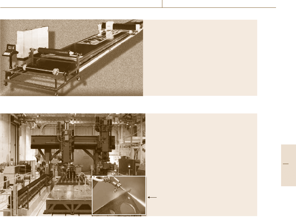
• Typical configuration: flat bed two-axis gantry
• Work zone: up to 10 ft × 100 ft
• Cutting speed: up to 1000 in/min
• Rapid traverse speed: 2000 in/min
• Positioning accuracy: 0.002 in/ft–0.015 in overall
• Knife: 20000–30000 strokes/s
Fig. 51.10 Two-dimensional ultrasonic cutting machine
Insert shows a 60000 psi waterjet
stream cutting a part
Technical data
• Precision multiaxis overhead gantry, 5 up to 11 axes
• Work zone: up to 20 ft × 50 ft × 5 ft
• Cutting speed: up to 250 in/min
• Rapid traverse speed: 1200 in/min
• Positioning accuracy: 0.002 in/ft–0.015 in overall
• Thin stream: 0.020 to 0.050 in dia.
Fig. 51.11 Gantry abrasive water jet with pogostick tooling
conventional machining techniques does not work very
well, since heat and the abrasive nature of compos-
ites tend to wear out cutters rapidly and delaminate
or pull fibers out of the adhesive matrix. Abrasive
water jets are being used extensively to trim, and in
some cases drill, holes in these materials due to the
clean cut, low fiber pull out, and little or no de-
lamination. The majority of water-jet systems used in
aerospace are high-pressure (60 000–87000psi) gar-
net or aluminum-oxide grain abrasive water-jet units
(Fig.51.11).
An N/C machine positions a high-pressure abrasive
water jet near the periphery of a composite part that is
held in the correct contour by a series of headers or po-
gos (Fig.51.11). The computer program drives the N/C
machine in a very accurate path at various speeds to cut
off the excess material and provide the finished edge of
the part.
51.2.6 Automated Tape Layup Machine
Automated tape layup (AT L) is an additive process used
to construct large structures from composite prepreg
tape material. It is primarily used in the aerospace in-
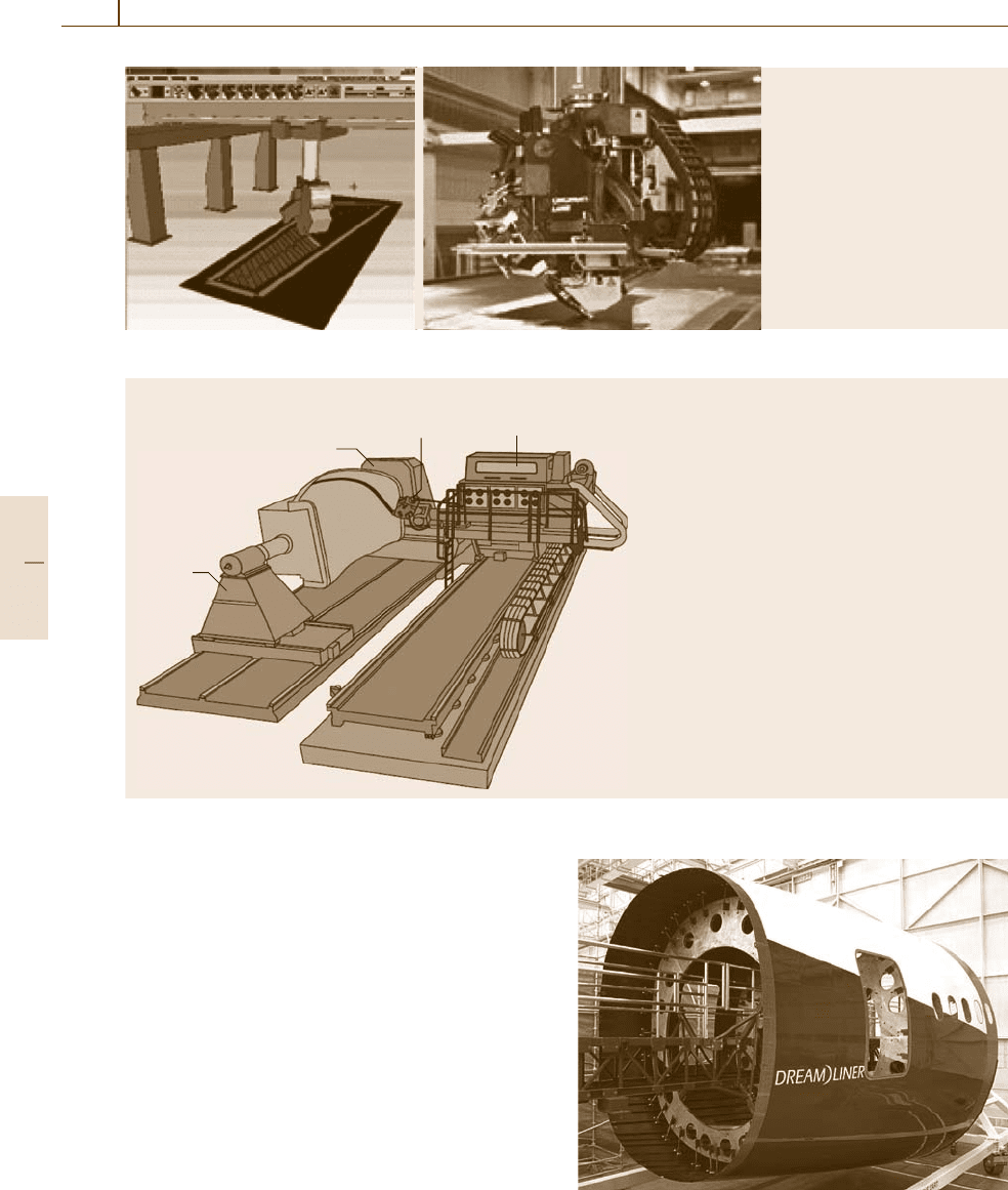
dustry. Machines typically have a five-axis precision
overhead gantry and an application head that is sus-
pended from a cross rail. The machine motion and
head functions are controlled by a computer with spe-
cialized programming. Prepreg tape is typically more
than 3 in wide, which is suited to flat or mild contours
(Fig.51.12).
The highly specialized head can precisely lay any
number of plies of composite filament tape, in any
desired orientation, assuring consistent part shape,
thickness, and quality. A typical machine draws from
supply reels, then deposits 3, 6 or 12in tape on flat or
mild-contour layup tools. The layup heads can heat the
Part F 51.2
902 Part F Industrial Automation
Technical data
• Precision five-axis overhead
gantry with multifunction head
• Work zone: up to 20 ft × 100 ft
• Feed rate: up to 1200 in/min
• Traverse speed: 2200 in/min
• Positioning accuracy: 0.002
in/ft–0.015 in/overall
• Layup rate: up to 50 unknown
unit lbs/h
Fig. 51.12 Overhead gantry with work piece below and multifunction tape application head
Technical data
• Precision multiaxis platform with horizontal ram
with multifunction head
• Work zone: up to 20 ft dia./times 75 ft
• Working feed rate: 1200 in/min
• Traverse speed: = 2200 in/min
• Positioning accuracy: 0.002 in/ft–0.015 in/overall
• Layup rate: up to 30 unknown unit lbs/h
Fiber placement
head, mounted to
a roll-bend-roll wrist
Headstock
Tailstock
Refrigerated creel
containing bidirectional
tensioners
Fig. 51.13 Automated fiber placement machine
tape prior to laying it down, then compact or compress
the tape after it isplaced on the layup tool. Each layer or
ply of tape can be oriented in a direction that optimizes
the specific desired part characteristics [51.9–15].
51.2.7 Automated Fiber Placement Machine
Automated fiber placement (AFP) machines, such as
that shown in Fig. 51.13, combine two technologies
widely used in industry: automated tape layup (ATL)
and filament winding (FW). The AFP processisusedby
the aerospace industry to construct large-circumference
and complex structures such as fuselage barrels, ducts,
and pressure vessels from composite prepreg materials.
The Boeing 787 fuselage barrel in Fig.51.14 is a pri-
mary example [51.9–15].
Fig. 51.14 Boeing 787 fuselage barrel
Part F 51.2

Aircraft Manufacturing and Assembly 51.3 Automated Part Inspection Systems: Examples 903
Redirect
roller
Compaction roller
Clamp
Restart rollers
Cutters
Controlled head
Individual tow payout
with controlled tension
Fig. 51.15 Automated tape layup process head
This additive process utilizes relatively narrow
strips of unidirectional composite prepreg tape, com-
monly called tow, which have unidirectional fibers
preimpregnated with a thermoset resin that is later
cured. Central to the process is the fiber placement ma-
chine, basically a seven-axis manipulator with a head
(Fig.51.15) thatarrays a group of tows side-by-side into
a continuous band and compacts them against the sur-
face of a concave, convex, contoured combined layup
mandrel. The mandrel is mounted on a trunion system
similar to a lathe, so that it can rotate as the manipula-
tor is placing the tow. AFP combines the advantages of
both filament winding and automated tape layup. The
raw materials used are tow-preg or slit-tape rolls of
aramid, fibreglass or carbon fiber, preimpregnated, typ-
ically with epoxy resin. The width of tow or slit-tape
ranges from 3.2mm to 6.4 mm with thicknesses rang-
ing from 0.13mm to 0.35mm. Typical systems permit
the use of 12, 24, or 32 tows simultaneously and can
lay up on the top of a honeycomb core without degrad-
ing it.
51.3 Automated Part Inspection Systems: Examples
The nondestructive inspection (NDI) of aircraft sys-
tems is performed at the very highest level of sensitivity
because of the criticality of the components. X-ray ra-
diography is the primary method for the inspection of
metallic components, particularly welds in tubes and
ducts of titanium and inconel as well as other aerospace
welded joints [51.1, 2]. Ultrasonic inspection is the
primary method for carbon-fiber polymer compos-
ites [51.3,4]. Both x-ray and ultrasonics benefit in terms
of quality and value by the implementation of highly
automated systems. Ultrasonic systems have required
major developments in robotics for inspection rate and
sensitivity requirements for both production [51.5–7]
and for field in-service inspection operations [51.8, 9].
Automated x-ray systems have been slower to be im-
plemented, but progress is being made. The future
direction in aircraft part inspection will be automated
interpretation of the NDI data that is currently being
implemented in higher-production-rate industries.
51.3.1 X-ray Inspection Systems
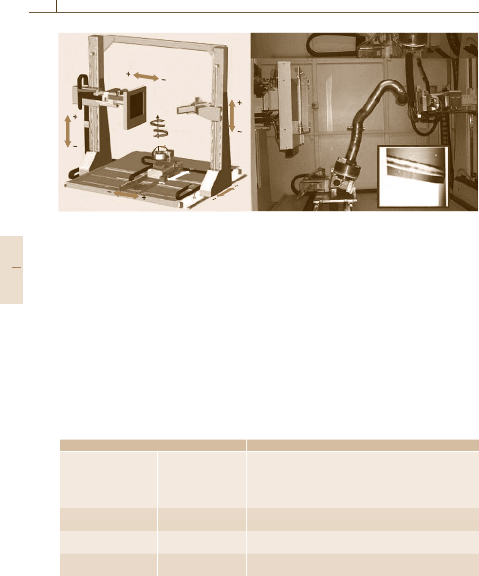
Figure 51.16 shows a diagram and photograph of
a seven-axis CNC system for digital radiography (DR)
of welds at Boeing Commercial Airplanes Fabrication
Division in Auburn, WA, USA. The CNC manipu-
lator, source, and detector are located in a radiation
vault. A complex welded duct is positioned by the CNC
manipulator at a series of preprogrammed locations be-
tween the x-ray source and digital detector, as shown
in the right-hand image. The insert in the lower right
of the figure shows the DR image from the opera-
tor’s console display. The system consists of five major
components: the Siemens controller-based CNC ma-
nipulator, the x-ray source, the digital x-ray detector,
the control computer for the CNC manipulator, and the
image display and analysis system. The system require-
ment is for x-ray image quality indicator sensitivity of
1-1T (1% part thickness with visible hole of 1% part
thickness diameter) in the radiographic image for 100%
coverage of the part. To achieve this image quality an
x-ray spot size of 20μm nominal and a magnification
of 4.5× is used to create images with greater than ten
line-pairs per millimeter resolution and better than 1%
contrast sensitivity. Position of the weld to be inspected
is critical to achieving the required image quality and
this is accomplished by automated control of the CNC
manipulator. Table 51.1 lists the critical characteristics
of the CNC manipulator system. The CNC manipulator
is programmed to begin a testing session by positioning
and imaging a test standard at the same geometric fac-
tors, exposure parameters, and image display settings
as will be used for the part to be inspected. Once the
operator approves the quality of the inspection for the
Part F 51.3
904 Part F Industrial Automation
X
Z
X'
Z'
–B' (CW)
+B' (CCW)
(back) + (fwd)
Y'
Y
C' (tilt)
DR image
of weld
Fig. 51.16 Diagram and photograph of robotic digital radiography system (courtesy of Boeing)
standard, inspection of the part begins. Each part con-
figurationisprogrammedintheCNC manipulator to
allow the weld to be 100% inspected by a series of ra-
diographic views. The CNC manipulator positions the
part according to the program for an exposure at the
first location. Following operator review of the result-
ing radiographic image, the CNC manipulator advances
to the next position in the sequence and the process
repeats until the entire part is inspected. Typical inspec-
tion sequences for the CNC manipulator include 20–50
views, taking approximately 10–20min. Images are re-
viewed by automated sequence of viewing parameters
followed by preset adjustments of the image display
for enhancement of areas of interest for detail review.
Enhancement and measurement features include differ-
ent window/level parameters, digital magnification, and
contrast enhancement [51.16–28].
Table 51.1 Boeing commercial airplane robotic x-ray system characteristics
Characteristic Values
Robot Type Siemens Simotion seven axis
Range of motion Magnification axis: ≈1.5m, loading axis: 0.3m, rotation axis: 360
◦
,
tilting table axis: ±60
◦
Positional accuracy 0.5 mm, angular axis <1
◦
Load-carrying ability 70 kg
X-ray source Model FEINFOCUS, Model: FXE-225, 320W (225kV at 1400mA)
Spot size Less than 20 μm
Detector Model Perkin Elmer 1620
Pixel size/bit depth 200μm/16bit
Weld radiography quality Image quality 1-1T, with >10line pairs/mm at 4.5×
Inspection time 10s per view, 30s to 1min per weld
51.3.2 Ultrasonic Inspection Systems
For carbon-fiber polymer composite materials includ-
ing laminate, sandwich structure, and bonds, ultrasound
is the principle inspection method and requires highly
automated scanners to keep up with the production rate.
Sophisticated automation is also needed to handle the
complex contoured geometry of the large composite
assemblies. Ultrasonic scanning systems can be con-
structed in a variety of forms from small portable units
to large gantry systems. Ultrasonic inspection is most
commonly performed with some type of water coupling
of the ultrasonic energy between the piezoelectric trans-
ducer and the test part. Methods include: immersion
where the part is submerged in a water bath with the
transducer; bubbler systems, where the transducer rides
on the surface in a shoe that also has a flow of water;
Part F 51.3
