Mrinal K Pal. Power system stability
Подождите немного. Документ загружается.

VOLTAGE STABILITY
10-23
These assumptions are rather drastic. We will not, however, try to justify the assumptions.
Rather, our objective is to see where all these lead to, if the analysis results are interpreted
correctly.
We will use a simple example system and follow the steps as generally followed in the literature.
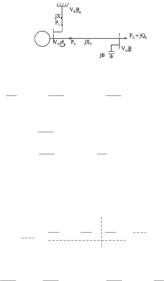
The system is shown in Figure 10.15. A single generator is connected to an infinite bus through a
transmission line, and also serving an isolated load at the end of another transmission line.
Although this is a very simple power network, it has all the essential features that can give rise to
both voltage and angle instability. The reason for using this simple system is that the analysis
steps and results will be easily tractable and, therefore, directly verifiable.
Fig. 10.15 An example three-bus system
From Figure (10.15) we can write
glg
LG
sg
SG
Mg
D
X
VV
X
VV
P
H
θθθθθθ
ω
&&&
−−−−−= )sin()sin(
2
21o
(10.35)
The load power balance equations are:
BV
X
V
X
VV
Q
X
VV
P
L
L
lg
LG
L
lg
LG
L
2
2
2
2
2
)cos(
)sin(
+−−=
−=
θθ
θθ
(10.36)
Loads can be assumed as either constant MVA static load or some function of voltage. We will
assume the former. The final conclusion will, however, be the same with either type of laod.
We can linearize (10.35) and (10.36) around an operating point and, noting that
0
=
∆
=∆
LL
QP
for constant power static load, arrive at the following equation:
∆
∆
∆
∆
−=
∆
∆
L
l
g
g
g
g
V
H
D
HH
θ
ω
θ
ωωω
ω
θ
43
2
oo
1
o
222
10
A0A
AA
0
0
&
&
(10.37)
where
A
1
, A
2
, A
3
, and A
4
are functions of system parameters and initial state and given by
−=−−=
gl
G
gl
LG
gl
LG
gs
SG
X
V
X
VV
X
VV
X
VV
θθθθ
sincos,coscos
22
2
21
1
AA

VOLTAGE STABILITY
10-24
−
−
−
=
−
=
2
2
22
22
4
2
2
3
1
2cossin
sincos
,
sin
cos
X
BX
V
X
V
X
VV
X
V
X
VV
X
VV
X
VV
Lgl
G
gl
LG
gl
G
gl
LG
gl
LG
gl
LG
θθ
θθ
θ
θ
AA
After eliminating the non-state variables, (10.37) reduces to
[]
∆
∆
−−
=
∆
∆
−
g
g
g
g
H
D
H
ω
θ
ωω
ω
θ
22
10
oo
3
1
421
AAAA
&
&
(10.38)
Equation (10.38) is of the form
Axx
=
&
. The stability of the system is determined by the
eigenvalues of
A. At stability limit one of the eigenvalues will become zero. This will be
indicated by the determinant of
A becoming zero.
[
]
3
1
421
o
det
2
det AAAAA
−
−−=
H
ω
The system power flow Jacobian is
−=
43
21
AA
AA
J
Using the expressions for
A
1
, A
2
, etc. the determinant of J can be computed as
4
1
detcosdet AJ
gs
SG
X
VV
θ
= (10.39)
The determinant of
J can also be expressed as
AA
AAAAAAJ
4
o
1
43
1
4214
2
existsif,det
ω
H
=
−−=
−−
or
4
o
2 A
J
A
H
ω
=
(10.40)
Equation (10.40) gives the impression that when |
J| is zero |A| is zero, and therefore the
singularity of
J signifies voltage stability limit. Actually, however, we can see from (10.39) that
unless
θ
gs
= 90° (which is the angle stability limit), |J| = 0 implies that |A
4
| = 0, and, therefore,
singularity of the power flow Jacobian (or the saddle node or static bifurcation) means nothing as
regards stability. Singularity of the power flow Jacobian signifies loadability limit and nothing
else. As an extension, all related methodologies based on similar concepts, such as, modal
analysis, point of collapse, static voltage stability indices, etc. [4 - 17] are therefore equally
invalid.
The confusion clears up when one carries out the operations indicated in (10.38). After carrying
out the indicated operations we obtain

VOLTAGE STABILITY
10-25
−−
=
D
HX
VV
H
gs
SG
2
cos
2
10
o
1
o
ω
θ
ω
A
so that
gs
SG
X
VV
H
θ
ω
cos
2
det
1
o
=A (10.41)
The above expression clearly shows that, for the assumed load model, there can be no voltage
instability, only angle instability, which occurs when
θ
gs
reaches 90°. The same conclusion also
follows from (10.39) and (10.40), from which we can write (10.41). This is a consequence of
using a static load model in the analysis, and is to be expected. In fact, the mathematical steps
just described are quite unnecessary when one observes that for constant power load, ∆P
L
(=
∆P
2
) is identically zero. Therefore (10.41) follows directly from (10.35)
Consider an example where V
G
= 1.0, X
2
= 0.5, P
L
= 1.6, and Q
L
= 0. V
L
is held at 1.0 by
providing sufficient reactive support in the form of discrete capacitors. The network solution
yields
θ
gs
= 53°, B = 0.8. This represents operation in the lower portion of the PV curve, drawn
with respect to constant V
G
. It will be shown later that for real life constant power load, operation
in this region is unstable. However, the above analysis shows otherwise.
If in the above analysis the effect of generator rotor flux dynamics were included, the results
would have been even more dramatic. The movement of the eigenvalues with load increase
would at first appear logical. However, instability will set in at a load level which would be
typically well below the maximum as determined from a power flow model. If the computation
is continued beyond the maximum power point, into the lower portion of the PV curve
(corresponding to the low voltage solution), the eigenvalues will again show stable operation.
(This is left as an exercise.) Obviously, this is not what one would experience with real life
constant power load. This behavior can, however, be explained on the basis of the static constant
power load model.
A constant power load is not a static load. This means it cannot jump instantaneously from one
demand level to another as the demand changes. Similarly, following a system change, there is a
momentary change in the load, which is then restored to the constant power level, either due to
the nature of the load itself, or due to the action of some control mechanism. A definite time lag
is involved in the process. It will be shown later that if the overall characteristic of the composite
load is constant MVA, and the mechanisms that restore the load to constant MVA act much
slower compared to the speed of system voltage control, voltage stability limit is the same as the
power limit as obtained from a conventional power flow model.
Voltage Stability: Effect of Load Characteristics
The problem of reactive power and voltage control, i.e., maintaining an acceptable system
voltage profile by providing adequate reactive supports at appropriate locations so as to meet
system reactive needs efficiently, is well understood and reported extensively in the literature [1,
2]. It is not, however, well appreciated that maintaining a good voltage profile does not
automatically guarantee voltage stability, and that voltage instability need not be associated with
low voltages, although frequently it is.
VOLTAGE STABILITY
10-26
Voltage instability is largely determined by load characteristics and the available means of
voltage control. For true voltage instability at least a part of the total load must be of self-
restoring (constant MVA) type. By the same token, voltage stability problem becomes less
severe as static or voltage sensitive loads constitute a portion of the total load.
System and load model
To develop a basic understanding of voltage stability we will assume that voltage instability can
be (although it need not be) studied in isolation, i.e., by separating it from the angle
(synchronous) stability aspects. We will concentrate only on the dynamics that are likely to have
appreciable impacts on voltage stability. The dynamics that affect voltage stability are the
dynamics of the load and the dynamics of the voltage control devices, especially those of the
generator excitation controls.
Important insights into the mechanisms of voltage instability and collapse can be obtained
through the use of a simplified model, incorporating only the elements that are dominant in
controlling these mechanisms. The conclusions drawn from the simplified analysis can then be
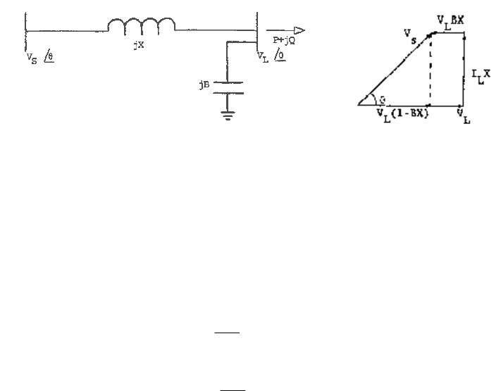
verified by detailed simulations. The power system we will analyze is shown in Figure 10.16. A
voltage source, which may be a generator terminal bus or an infinite system, is supplying a load
over a transmission line. For simplicity, all resistances and line chargings have been neglected.
However, any reactive support that might be present at the load end of the transmission line has
been included.
Fig. 10.16 Voltage source supplying load through transmission line. Phasor diagram drawn at
unity pf
Load models that have been used in voltage stability studies can be generally classified into
static and dynamic models. Although voltage stability is a dynamic phenomenon, a static model
is perfectly acceptable if the load is static. Loads are considered static if they are functions of
voltage, and can be modeled as such without needing any dynamic description (e.g., the use of
differential equations). Examples are constant impedance and constant current loads. A common
representation of static loads is
b
L
L
L
a
L
L
L
V
V
QQ
V
V
PP
=
=
0
0
0
0
(10.42)
By choosing appropriate exponent values, the above model can represent constant impedance or
constant current loads. When both exponent values are zero, the load becomes a constant MVA
load.

VOLTAGE STABILITY
10-27
The most stringent load from the viewpoint of voltage stability is the load that maintains a
constant MVA characteristic, either due to the nature of the load itself or due to the action of
control mechanisms that are intended to maintain constant voltage at the load supply point, such
as LTC’s, distribution voltage regulators, etc., thereby rendering any load constant MVA. (Note
that even without voltage control action, certain apparently static loads, such as thermostatically
controlled heating loads, due to their constant energy consumptions, tend to behave as constant
MVA loads in the longer term.) We will therefore concentrate primarily on constant MVA loads,
and show the effect on voltage stability when parts of the load possess characteristics other than
constant MVA, such as constant impedance.
In a voltage stability analysis it is important to model the relevant dynamics of the load. As will
be shown later, employing a static model for constant MVA loads can lead to erroneous and,
often, misleading results. A constant MVA load is not a static load. This means it cannot jump
instantaneously from one demand level to another as the demand changes. Following a change in
the demand the load will at first change according to its instantaneous characteristic, such as
constant impedance or current. It will then adjust the current drawn from the system until the
load supplied by the system satisfies the demand at the final system voltage. Similarly, when
there is a sudden change in the system voltage, such as following a disturbance, the load will
change momentarily. It will then adjust the current (or impedance) and draw from the system
whatever current is necessary in order to satisfy the demand. The process is not instantaneous. A
definite time lag is involved. A load model, in order to be suitable for voltage stability analysis,
must recognize this basic fact.
Since our purpose is to develop an understanding of the basic issues in voltage stability, we will
adopt the simplest load model that satisfies the above characteristic of the constant MVA load so
as to keep the analysis procedure simple while preserving the qualitative behavior of the system
response. The simplified reduced order model of the induction motor -- the steady-state
equivalent circuit along with the equation of motion, and assuming constant mechanical torque
(see Chapter 7) -- can be used as a starting point. The model is used in the study of voltage
stability in the presence of induction motor load, presented later in the chapter. Further
simplification of the model by neglecting the stator resistance and all reactances yields the
following form
GVPGT
LL
2
0
−=
&
(10.43)
The above applies to a unity power factor load. (For reactive power load a separate equation with
G replaced by B may be used.) G plays the role of a load conductance which is adjusted to
maintain constant power, and P
0
is the power set point. The model describes the basic dynamics,
pertinent to voltage stability, of a wide variety of loads that recover, more or less exponentially,
to constant power (e.g., static loads controlled by tap changers or other control devices), the
specific time delay approximately reflecting the response characteristic of the particular load.
A general form of the above model can be found in the literature, and may be expressed as
n
L
L
LL
V
V
GVVPGT
−=
0
2
0
)(
&
VOLTAGE STABILITY
10-28
for the real power, and similarly for the reactive power. Note that the model is only valid for n ≥
1. For n < 1, it can be shown that the stability behavior of the model in certain operating ranges
may be contrary to physical experience [4].
Other load models can be found in the literature on voltage stability. An example is a model
using two components: a static component comprising a polynomial or exponential function of
the load bus voltage, and a dynamic component comprising time derivatives of the load bus
voltage and angle. The general form of this model is
LL
LL
VkkVQQ
VkkVPP
&
&
&
&
43
21
)(
)(
++=
++=
θ
θ
(10.44)
An assessment of the model in regard to its pertinence and validity in voltage stability studies
will be provided later in the chapter.
Region of attraction
We now examine the region of attraction of the stable equilibrium point in the context of the
system power voltage (PV) curves. Consider the simplified radial power system with constant
sending-end voltage in Figure 10.16. Assuming , for simplicity, a unity power factor load, the PV
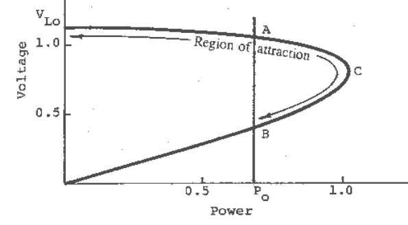
curve of the post-disturbance system is shown in Figure 10.17. For a constant power load P
0
, the
load characteristic, as shown by the vertical line, would intersect the system PV curve at two
points, A and B, corresponding to the two possible equilibrium points. Point A, on the upper
portion of the system PV curve (the high voltage solution), is a stable equilibrium point, whereas
point B, on the lower portion of the PV curve (the low voltage solution), is an unstable
equilibrium point. This may be verified by linearizing equation (10.43) around the equilibrium
points, and applying the condition for stability.
Fig. 10.17 Power voltage curve of system shown in Fig. 10.16.
It will be shown that if the state reached at the end of the disturbance lies anywhere on the
portion V
Lo
ACB of the PV curve, the post-disturbance system will be stable, i.e., the operating
point will settle at the stable equilibrium point A. The region V
Lo
ACB, i.e., the region of the PV
curve to the right of the unstable equilibrium point is the region of attraction of the stable
equilibrium point of the post-disturbance system.
From the phasor diagram (Fig. 10.16)
VOLTAGE STABILITY
10-29
222
2
2
)1( XGBX
V
V
S
L
+−
= (10.45)
Equation (10.43) can therefore be expressed as
[
]
222
2222
0
)1(
)1(
XGBX
GVXGBXP
GT
S
L
+−
−+−
=
&
222
2
2
2
0
2
22
0
)1(
)1(
XGBX
X
BX
G
XP
V
GXP
S
+−
−
+−
=
222
2010
2
0
)1(
))((
XGBX
GGGGXP
+−
−−
= (10.46)
where
2
0
222
0
42
20,10
2
)1(4
XP
BXXPVV
G
SS
−−±
=
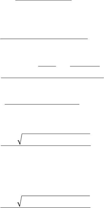
The two values of G correspond to the two steady-state solutions of G for the given power P
0
. In
Figure 10.17 these two solutions correspond to the equilibrium points B and A, respectively. The
two voltage solutions, from (10.45) and noting that, in the steady state,
2
0
/
L
VPG = , are
2
222
0
42
2
)1(2
)1(4
BX
BXXPVV
V
SS
L
−
−−±
=
The higher value of G corresponds to the low voltage solution, and vice versa. This is verified by
noting that
010
2
220
2
1
PGVGV
LL
==
Equation (10.46) shows that if the initial state is to the left of the point A on the PV curve (G less
than G
20
), dG/dt is positive and therefore, the operating point will move to A, at which point
dG/dt = 0. Similarly, if the initial state is anywhere on the portion ACB (G
20
< G < G
10
), dG/dt is
negative and therefore the operating point moves to A. If the initial state is to the left of B, dG/dt
is positive and the operating point moves further away from B. The region to the right of B is
therefore the region of attraction of the stable equilibrium point A.
A physical explanation can be provided as follows: Consider an initial state in the lower portion
of the PV curve but to the right of the unstable equilibrium point B. Since in this state the power
delivered is greater than the set-point power P
0
, the constant power control mechanism would
decrease the current or admittance in order to bring the power down. This will, however, increase
the power still further, since the voltage will increase at a faster rate with decrease in current or
admittance in this region. The operating point will therefore move up the PV curve until point C
is reached. From this point onwards the same control command will, however, decrease the
power. The process will continue until the stable equilibrium point A is reached. Using the same
argument it can be seen that starting from anywhere on the upper portion of the PV curve, the
VOLTAGE STABILITY
10-30
operating point will move to the stable equilibrium point and that, starting from an initial state to
the left of B, it will move further away. The region to the right of B is therefore the region of
attraction of the stable equilibrium point A.
Large disturbance voltage stability with constant source voltage
It will now be shown that when the source voltage can be assumed constant, voltage stability is
assured by the presence of a stable equilibrium point in the post-disturbance system. In a typical
utility system, even when the loads possess constant MVA characteristics, the overall response
time may be quite slow. Immediately following a disturbance all loads temporarily behave as
static loads, e.g., constant impedance. It is either the nature of the load itself, or the action of
some control mechanism that eventually restores the load to constant MVA. We will assume that
the mechanisms by which much of the load would be rendered constant MVA act slowly
compared to the speed of response of the voltage control equipment, which are primarily
generator excitation controls. Voltages at the controlled buses, e.g., the generator terminal
voltages would therefore be restored well before the overall load characteristics return to
constant MVA. In situations when the bulk of the load has fast response characteristics, this
assumption is not valid and can introduce considerable error. These cases will be discussed later.
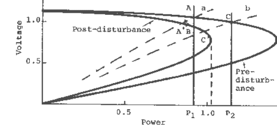
Consider the system shown in Figure 10.16, initially supplying a load P
1
. Assume a disturbance
caused by opening one circuit of a double circuit transmission line. The pre- and post-
disturbance system PV curves are shown in Figure 10.18. For initial load power P
1
, the operating
point is A, the intersection of the vertical line at P
1
and the steady-state pre-disturbance PV
curve. Immediately following the disturbance the load will behave as constant impedance. If the
system voltage can be assumed to be restored well before the load returns to constant power, the
operating point will temporarily move to point A′, the intersection of the instantaneous load
characteristics shown by the dashed curve a, and the steady-state post-disturbance PV curve.
Since A′ is within the region of attraction of the final steady-state equilibrium point B, the
operating point would move to B and the system would be stable. The existence of a stable
equilibrium point in the final post-disturbance system, therefore, guarantees voltage stability.
Fig. 10.18 System PV curves and steady-state and instantaneous load characteristics.
If, on the other hand, the initial load were P
2
(greater than the maximum power that can be
supplied by the post-disturbance system), the operating point would temporarily move to C′
following the disturbance. Since there is no equilibrium point for the post-disturbance system at
the assumed load, voltage collapse will ensue if the load attempts to maintain constant power. If

VOLTAGE STABILITY
10-31
the speed of response of load recovery is slow, the collapse will not be immediate and sufficient
time may be available for applying corrective measures to restore stability.
Note that although we have used a two-bus system the results obtained apply to systems of any
size. This is because for every bus in a large system, PV curves similar to those shown in Figure
10.18 can be generated using a power flow program, and the arguments presented above can be
repeated. .
The voltage stability limit for constant MVA load whose response time is slow compared to the
speed of response of the system voltage control, is the same as the power limit (in the literature
this has been called the steady-state voltage stability limit without proper qualifications),
obtained from the standard power flow model. In using the power flow model, the status of the
system voltage control is important and should be reflected in the model. If the generator
terminal voltages are not maintained by excitation control, i.e., when the generators are operating
at constant excitations, a modification to the power flow model would be necessary. It will be
shown later that under this condition the voltage stability limit and, therefore, the stable
equilibrium point are determined by constant voltage (generator field voltage) behind generator
synchronous reactance. Failure to recognize this may result in gross error.
Voltage stability limit when part of the load is static
Although voltage instability cannot occur for static load, the maximum power that can be
delivered at a given power factor is independent of the type of load. Beyond the point at which
maximum power occurs, the actual power delivered will decrease with increased demand. We
will now investigate the voltage stability limit when a portion of the load is static. Assuming, for
simplicity, unity power factor, and a combination of constant power and resistive load, the total
load can be expressed as
)(
2
LL
GGVP += (10.47)
where G
L
is the conductance of the resistive part of the load, and G is the conductance of the
constant power part of the load whose dynamics is given by (10.43)
From the power balance equations and using (10.47), we can write (also follows from the phasor
diagram of Figure 10.16)
θ
sin)(
SLL
VXGGV
=
+ (10.48)
θ
cos)1(
SL
VBXV
=
− (10.49)
Linearizing (10.43), (10.48) and (10.49), and eliminating the non-state variables, we obtain
G
BXXGG
GX
VGT
L
LL
∆
−++
−−=∆
)1(tan)(
tan2
1
2
θ
θ
&
Using (10.48) and (10.49), the above reduces to
G
GG
GG
VGT
L
L
LL
∆
+
+
−=∆
θ
2cos
2
&
(10.50)
For stability
02cos >+
L
GG
θ
, which yields
VOLTAGE STABILITY
10-32
0
2
2cos
P
GV
LL
−>
θ
(10.51)
where )(
2
0
GVP
L
= is the constant power part of the load.
Voltage stability limit is reached when
0
2
2cos
P
GV
LL
−=
θ
(10.52)
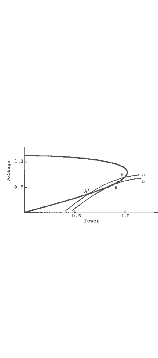
Referring to Figure 10.19, assume that the load characteristic for a given load combination of
constant power and resistive load is as shown by curve a. It intersects the system PV curve at
points A and A′. It will now be shown that point A (although it is on the lower portion of the
system PV curve) is a stable equilibrium point, whereas point A′ is unstable.
In order to prove the above, we first increase the load until a limit is reached, i.e., until the load
characteristic becomes tangent to the system PV curve. The load increase can be achieved by
increasing either the constant power part or the resistive part of the load, or both.
Fig. 10.19 System PV curve and load characteristics for a combination of constant power and
resistive load.
We have
θ
sin
2
0
X
VV
GVP
LS
LL
=+ (10.53)
Substituting V
L
obtained from (10.49) into (10.53), we obtain
θθ
2sin
)1(2
cos
)1(
2
2
2
2
0
BXX
V
BX
GV
P
SLS
−
=
−
+ (10.54)
To obtain the limit, we take the derivative of either P
0
or G
L
with respect to
θ
, and equate to zero.
After some algebraic manipulations we arrive at the condition at limit as
0
2
2cos
P
GV
LL
−=
θ
(10.55)
which is the same as the voltage stability limit obtained above (10.52).
