Mrinal K Pal. Power system stability
Подождите немного. Документ загружается.

VOLTAGE STABILITY
10-53
operating point may be at a much lower voltage with consequent reduction in the load power
delivered, which may or may not be acceptable.
Several points need to be kept in mind while considering implementation of a viable load
shedding program.
1
There is a minimum amount of load that needs to be shed in order to restore stability.
2
Unless prompt load shedding is initiated, more load would need to be shed than necessary.
This might lead to the opposite problem of high voltage.
3
Although low voltage would be a good indicator for initiating load shedding, low voltage alone
need not be used as a reason for load shedding, unless the low voltage itself is unacceptable.
Any undervoltage load shedding scheme should also take into account the rate of drop of
voltage in order to ensure the need for an immediate load shedding. A fast rate of drop of
voltage would indicate voltage instability caused by stiff load, e.g., motor load. This would
require prompt shedding of such loads.
Capacitor switching
In the previous example, instead of load shedding, additional capacitors, if available, could be
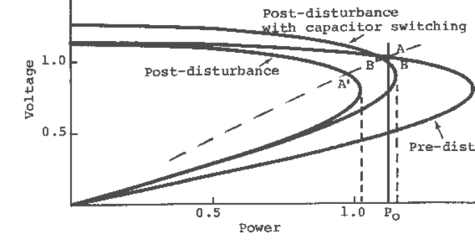
employed in order to restore a stable equilibrium point. This is illustrated in Figure 10.30.
Immediately following the disturbance the system state moves to A′. If a sufficient quantity of
capacitors are promptly switched on at or near the load bus, so that a stable equilibrium state is
possible, and the initial state following the capacitor insertion is within the region of attraction of
this stable equilibrium state, stability can be maintained. In the illustration of Figure 10.30, the
system state moves from A′ to B′ following capacitor insertion, then moves to B, the final stable
equilibrium point.
Fig. 10.30 Restoration of stable equilibrium point following a disturbance by capacitor
switching.
The necessity of prompt insertion of capacitors for maintaining stability should be clear from the
above illustration. The switching must be accomplished before the system state moves too far down
the post-disturbance PV curve. Beyond a certain point, no amount of capacitor switching will
restore stability. Again, the capacitor switching speed requirement is not as stringent when part of
the load is static. This is due to the shape of the overall steady-state load characteristic.
VOLTAGE STABILITY
10-54
Although load supplying capability can be greatly increased by providing reactive support by
capacitors at or near the load bus, beyond a certain power level, continuous adjustment of reactive
support as provided by SVCs or synchronous condensers would be required, if voltages are to be
maintained at acceptable levels. Maintaining normal voltage with reactive support at high power
transfer may mean operating in the lower region of the PV curve. As will be shown later, stable
operation in this region can be maintained by fast and continuous adjustment of reactive support as
provided by SVCs.
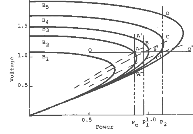
A conceptual understanding of the issues involved can be obtained by referring to Figure 10.31. The
system PV curves shown correspond to various amounts of reactive support at the load end.
Suppose the initial operating point is at A, corresponding to load P
o
and reactive support B
2
. With
continuous reactive support, adjusted to maintain constant load voltage, the operating point would
move approximately along the line OO′ as the load power is varied. (Stable operation along OO′
using SVC will be discussed in the next section.) The effect of providing reactive support by means
of discrete capacitors will now be investigated.
Suppose the load is increased to P
1
. From Figure 10.31, it is clear that without additional reactive
support this load cannot be maintained and, therefore, voltage collapse will occur. Now suppose an
additional reactive support is provided and the PV curve corresponding to B
3
applies. The operating
point will temporarily move to B′ (as the instantaneous behavior of all loads is static, the
instantaneous load characteristic following each load change would be as shown by the dashed
lines). As B′ is within the region of attraction of the stable equilibrium point B, the operating point
will eventually move to B. Note, however, that the voltage may be unacceptably high.
Fig. 10.31 Illustration of the issues involved in increasing load supplying capability using reactive
support by switched capacitors.
Following the same argument, it is clear that if the additional reactive support were provided at the
original load level P
o
, the operating point would have moved to A′, irrespective of whether the
initial operating point were on the upper portion (A), or the lower portion of the initial PV curve.
This is because the intersection of the instantaneous load characteristic and the PV curve
VOLTAGE STABILITY
10-55
corresponding to B
3
would fall within the region of attraction of the stable equilibrium point A′. A
steady-state analysis, on the other hand, will suggest that the operating point would move to A", if
the initial operating point were on the lower portion of the PV curve.
If, instead, the load is increased to P
2
, and sufficient reactive support for an equilibrium point to
exist in the steady state is provided, say B
4
, the operating point will momentarily move to C′. As C′
is outside the region of attraction of the stable operating point C, voltage collapse will occur. In
order to maintain stability, additional reactive support would have to be provided, and the operating
point will settle at an even higher voltage (in the example, the operating point settles at D
corresponding to a reactive support of B
5
).
If the reactive support were increased in anticipation of a load increase, the reactive requirement for
maintaining stable operation would be lower. In the example provided, a stable operating point C,
corresponding to load P
2
could be reached with reactive support B
4
, if the increase in reactive
support preceded the load increase. However, the problem of high voltage will still be present.
As before, it is not difficult to see that the situation is not so severe when a portion of the total load
is static.
Extending Voltage Stability Limit by SVC
If high voltage caused by simple shunt capacitors is not acceptable, or when fast control of load
voltage is required, the use of controlled reactive support such as provided by an SVC may be
necessary. Stable operation in the lower portion of the PV curve for constant MVA load (self-
restoring load) can be satisfactorily explained by simultaneously taking into consideration the
relevant dynamics of the load and the SVC control mechanism. Note that, for static load, such as
constant impedance, SVC is not necessary for maintaining voltage stability, although it will
certainly help in precise voltage control.
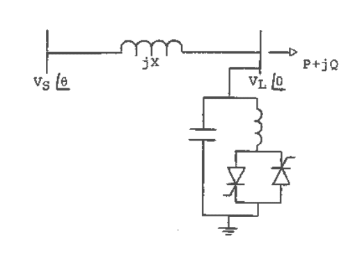
Fig. 10.32 A power system with constant sending-end voltage supplying a load whose voltage is
maintained constant by an SVC.
We now provide a simple but rigorous explanation of the mechanism of the extension of voltage
stability limit due to SVC. Consider the system shown in Figure 10.32, supplying a unity power
factor load whose voltage is being controlled by an SVC. An SVC acts by increasing capacitive
susceptance as the voltage drops from a set value and vice versa. For the present purpose, the
control logic of the SVC may be described by the simple first order delay model.

VOLTAGE STABILITY
10-56
LQ
VVBT −=
ref
&
(10.86)
where B is the SVC susceptance and T
Q
is a time constant. The load model is given by (10.43). The
power balance equations are:
θ
sin
2
X
VV
GVP
LS
L
== (10.87)
BV
X
V
X
VV
Q
L
L
LS
2
2
cos0 +−==
θ
(10.88)
After linearizing equations (10.43), (10.86) − (10.88), and eliminating the non-state variables, the
state-space model is obtained as
∆
∆
=
∆
∆
G
B
aa
aa
G
B
2221
1211
&
&
where
θθ
θθ
2cos,2sin
sin,2sin
2
2
22
2
21
2
1211
L
L
L
L
Q
L
Q
L
T
V
a
T
V
a
GT
V
a
GT
V
a
−=−=
=−=
For stability,
0,0)(
211222112211
>
−
>+− aaaaaa
. After some algebraic manipulation and noting
from (10.87) and (10.88) that tanθ = GX/(1-BX), the following stability condition results:
BX
X
VT
T
LQ
L
−
−>−
1
tan1
2
θ
(10.89)
Equation (10.89) shows that, when T
Q
<< T
L
, which would be true for most load types, the voltage
stability limit can extend to θ approaching 90
o
, i.e., well into the lower portion of the PV curve.
(Note that for unity power factor load, θ = 45
o
corresponds to the maximum power point on the PV
curve, the so-called static bifurcation point; θ > 45
o
corresponds to operation in the lower portion of
the curve. Also, beyond θ = 45
o
, the reactive requirement increases rapidly.) On the other hand if T
L
= 0, i.e., if the load adjusts to constant power instantaneously, the stability limit occurs at θ = 45
o
,
implying that no improvement in the voltage stability limit over that obtainable from static shunt
reactive support is possible. It may be of interest to note that if, in the above analysis, a constant
power static load model is used, the result will correspond to that for the dynamic load case with T
L
= 0.
The above analysis explains how an SVC can maintain stable operation in the lower portion of
the PV curve for real life constant power load. With an SVC, stable operation can be realized as
the load is varied at a given voltage level, for example, along the line OO′ as illustrated in Figure
10.31, or as the voltage set-point is varied at a given load power level, or for any combination
thereof.
The operation along the horizontal line OO′ in Figure 10.31 (in actual operation the SVC control
may not act like a simple integrator as implied by (10.86) and the line OO′ may have a small droop)
VOLTAGE STABILITY
10-57
is easy to visualize. For example, the instantaneous effect of a load increase is an increase in the
load admittance, resulting in a drop in voltage. The SVC responds by increasing the capacitive
susceptance until voltage is restored and the desired load level is reached.
In order to visualize stable operation at a given load level following a change in the voltage set-
point, consider a lowering of the voltage set-point. The SVC will initially decrease the capacitive
susceptance (cf. equation (10.86)). This will result in a decrease in voltage and hence in load, as the
instantaneous characteristic of the load is static. As the load tries to restore to the original level (cf.
equation (10.43)), the voltage will decrease further and the SVC will compensate by increasing the
capacitive susceptance. A stable operating point at the lower voltage level would be reached by an
eventual increase in the capacitive susceptance as long as T
Q
< T
L
.
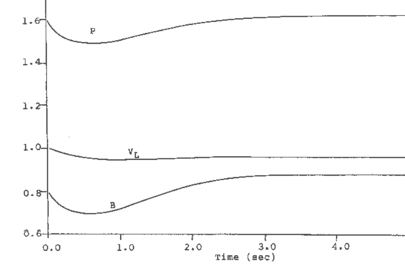
The above scenario is illustrated by the simulation results shown in Figure 10.33. Referring to the
system shown in Figure 10.32, the system parameter values and initial conditions are as follows: X
= 0.5, T
Q
= 0.1, T
L
= 1.0, V
S
= 1.0, V
L
= 1.0, P = 1.6, Q = 0.0. The initial operating point values are
computed as θ = 53.13° and B = 0.8. The initial operating point is thus in the lower portion of the
PV curve. Response curves shown in Figure 10.33 correspond to a change in the voltage set-point,
V
ref
, from 1.0 to 0.95. Note the behavior of the SVC output (B). Its initial response is in a direction
opposite to its final settling point.
Note that when the increase in reactive support corresponds to a decrease in voltage, the operation is
actually stable, contrary to the popular (static) definition of voltage instability.
Fig. 10.33 Response curves following a lowering of the voltage set-point of the SVC while
operating in the lower portion of the PV curve.
When the receiving-end voltage is being controlled by an SVC, and the SVC capacitive limit is
encountered, it would behave like regular capacitors. If the operation is on the upper portion of the
PV curve, there would be no stability consequence. However, the stability consequence of the SVC
VOLTAGE STABILITY
10-58
reaching its capacitive limit when the system is operating in the lower portion of the PV curve is of
considerable importance. Consider two scenarios: one in which the limit is reached while the SVC
is controlling the voltage in response to load increase, and the other where the SVC is trying to
restore voltage following a contingency. In the first scenario, referring to Figure 10.31, assume that
the desired operation is on the line OO′ as the load is increased from P
o
to P
2
. Now assume that the
SVC limit is reached so that, at limit, the PV curve corresponding to B
4
applies. At the time the SVC
limit is reached, the system state is at C′, the intersection of the instantaneous load characteristic and
the system PV curve corresponding to B
4
. As it is outside the region of attraction of the stable
equilibrium point of the final system, voltage collapse would occur if the load tries to reach the
constant power level P
2
. Note that the voltage would collapse even though a stable operating point
exists in the final system. It is not difficult to visualize that stable operation would be maintained if
the load had a substantial portion of static component.
In the second scenario, the SVC will try to restore the voltage, and will succeed if sufficient reactive
were available. If in the process of restoring voltage the limit is encountered, it is clear from the
argument presented earlier, that the system state at the time the limit is reached (the intersection of
the instantaneous load characteristic and the post-disturbance PV curve at the full SVC reactive
output) would be outside the region of attraction of the stable equilibrium point of the final system,
so that voltage collapse would take place. In the above scenario it was assumed that a stable
equilibrium state is possible in the post-disturbance system; however, an equilibrium point would
probably not exist if the load is of constant power type. As before, the situation would be less
stringent if static load comprised a portion of the total load.
LTC Operation and Voltage Stability
LTC operation can have either a beneficial or an adverse effect on voltage stability, depending on
the LTC's location with respect to the load point and the type of load. Blocking of LTC is often
advocated under voltage collapse situations [27, 29]. The argument for this is that normal LTC
operation tends to render any load constant MVA which, in turn, would aggravate any existing
voltage stability problem. Indiscriminate blocking of LTC, (or tapping down), without regard to the
type of load or the location of the LTC in relation to the load bus may, however, be counter-
productive.
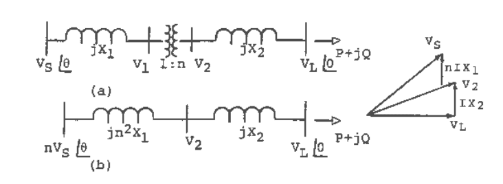
Fig. 10.34 A simple power system with LTC located away from the load bus and controlling
voltage locally: (a) original circuit, (b) Thevenin equivalent. The phasor diagram applies to unity pf
load.
The issues will be clarified by first presenting a basic analysis of voltage stability as affected by
LTC operation. For simplicity, consider a system as shown in Figure 10.34a, supplying a unity

VOLTAGE STABILITY
10-59
power factor load whose dynamic behavior is given by (10.43). For generality, assume the LTC
located away from the load bus and controlling the voltage locally, as shown in the figure. In this
way, the conclusions drawn from the analysis will also be applicable to induction motor loads, as
the circuit of Figure 10.34a, along with the load model (10.43), approximately represents a power
system supplying an induction motor load through a transmission line, with an LTC controlling the
load voltage. For clarity, shunt support is not included in the analysis. Its effect can be included by
simply modifying the source voltage and the reactance between the source voltage and the shunt
support point by a factor 1/(1-BX), where B is the shunt susceptance and X is the reactance between
the source voltage and the shunt point.
The analysis can be greatly simplified if the original circuit of Figure 10.34a is replaced by its
Thevenin equivalent shown in Figure 10.34b. The tap changer dynamics will be represented by a
continuous model similar to that given in Reference 31, and as shown by the following equation
2ref
VVnT
−
=
&
(10.90)
where n is the tap position and T is the time delay associated with tap changing. The load model is
given by (10.43). The power balance equations are:
θ
sin
21
2
2
XXn
VnV
GVP
LS
L
+
==
(10.91)
21
2
2
21
2
cos0
XXn
V
XXn
VnV
Q
L
LS
+
−
+
==
θ
(10.92)
Also, from the phasor diagram,
)1(
2
2
222
2
XGVV
L
+= (10.93)
After linearizing equations (10.43), (10.90) − (10.93), and eliminating the non-state variables, the
state-space model is obtained as
∆
∆
=
∆
∆
G
n
aa
aa
G
n
2221
1211
&
&
where
θ
θ
θθ
θ
2cos,
2cos2
)sincos(,
2cos
2
22
21
2
21
22
21
222
2
2
2
2
12
21
2
21
2
2
11
L
L
L
L
L
T
V
a
XXn
XXn
nT
GV
a
XG
GTV
V
a
XXn
XXn
Tn
V
a
−=
+
+
−=
−=
+
+
−=
For stability,
0,0)(
211222112211
>
−
>+− aaaaaa . After some algebraic manipulation the
stability conditions reduce to
)(
2cos
21
2
2
2
1
2
2
XXn
VT
TnV
Xn
X
L
L
++
−>
θ
(10.94)
2
1 GX> (10.95)
VOLTAGE STABILITY
10-60
The condition given by (10.95) is trivial; it simply refers to the voltage stability limit of the part of
the system with V
2
as the constant sending-end voltage. Therefore, it is necessary to concentrate
only on the condition given by (10.94). Note that for X
2
= 0, the stability condition reduces to cos2θ
> 0, i.e., θ < 45
o
, irrespective of the type of load. The stability limit corresponds to the maximum
power point. This is also the stability condition for constant power load without the LTC. LTC,
therefore, has no effect on voltage stability limit for constant power load when it is located at the
load bus. If the load exceeds this limit the voltage will collapse. Blocking of tap changing will help
avoid an impending collapse when the load is static. Note that certain apparently static loads, such
as thermostatically controlled electric space heating, tend to be dynamic, self-restoring in the longer
term. Tap changer blocking is not going to be very effective for such loads in the longer term,
although it will buy some time to initiate other measures.
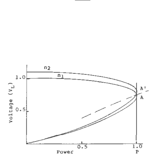
For constant power load, the effect of discrete tap changing when the load is at or close to the limit
may be of some interest. Depending on the margin left and the step size, raising the tap setting may
bring on instability. This is illustrated in Figure (10.35a). The initial operating point is at A, on the
PV curve corresponding to the lower tap ratio n
1
. A′ is the (stable) equilibrium point for this load
level corresponding to the higher tap ratio n
2
. In this illustration the operating point immediately
following the tap changing, given by the intersection of the instantaneous load characteristic and the
PV curve corresponding to the tap ratio n
2
, falls outside the region of attraction of A′, resulting in
instability.
For X
2
≠ 0, consider the following cases:
Case (i): Static load, T
L
= ∞, and (10.94) reduces to
1
2
2
2cos
Xn
X
−>
θ
(10.96)
Stability limit extends beyond θ = 45
o
, i.e., into the lower portion of the PV curve. This would be the
case if there is a substantial length of feeder circuit between the tap-changer and the load.
Case (ii): Constant power dynamic load with response time much faster than the LTC response
time, T >> T
L
. The stability condition reduces to cos2θ > 0, i.e., θ < 45
o
. The stable operation is
therefore confined to the upper portion of the PV curve.
a
VOLTAGE STABILITY
10-61
b
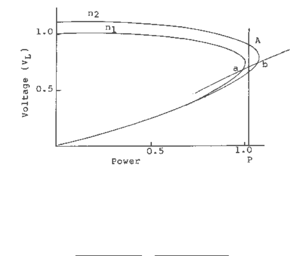
Fig. 10.35 PV curves for two values of tap ratio: (a) LTC connected directly to the load; (b) with an
impedance between LTC and load point.
The maximum power that can be delivered is given by
)/(2)(2
)(
2
21
2
21
2
2
max
nXX
V
XXn
nV
P
SS
+
=
+
= (10.97)
When X
2
= 0, the maximum power delivered is independent of the tap position. With the tap-
changer away from the load end, such as when there is a length of feeder circuit between the tap-
changer and the load, the maximum power is increased by raising tap position. (Recall that for
constant power load, an LTC does not affect the angle at which voltage stability limit occurs.) The
implication is that, while operating close to the limit, tapping down can have a detrimental effect.
This is illustrated in Figure 10.35b, which shows the PV curves corresponding to two tap ratios, n
1
and n
2
(n
2
> n
1
), when there is some impedance between the LTC and the load delivery point.
Suppose the system is delivering a constant power load P, at tap ratio n
2
. The operating point is at
A. As the power level exceeds the maximum power that can be delivered at tap ratio n
1
, tapping
down from n
2
to n
1
can initiate a collapse. The same argument can be made against LTC blocking
when there is a likelihood of a load increase beyond the maximum power that can be delivered at
the current tap setting.
Even for static load and operating in the lower portion of the PV curve, blocking or tapping down
can be counterproductive. This is illustrated in Figure 10.35b for the load characteristic ab. It is
evident that while operating at b, lowering of tap will cause both the power delivered and the load
voltage to go down. Similarly, while operating at a, raising of tap is preferable to locking.
As the circuit of Figure 10.34a approximately represents an induction motor whose terminal voltage
is being controlled by an LTC, it follows that tapping up near stability limit can be beneficial,
especially if there is some capacitive reactive support on the load side of the LTC.
Tap-changer dynamics act much slower than the dynamics of loads with inherently constant power
characteristics, such as induction motors. LTCs cannot, therefore, play any role in modifying the
dynamic voltage stability behavior due to such loads. If the induction motor has already become
unstable, i.e., it is in the unstable region of the torque-slip curve, raising or lowering of tap is not
likely to make much difference, considering the response speed of the motor and the limited range
VOLTAGE STABILITY
10-62
in the tap settings. The motor is going to stall, unless some mechanical load is shed somehow.
Similarly, in the stable region, tap changing will not affect the stability of the operating point
significantly. Raising the tap position would, however, raise the peak of the torque-slip curve
somewhat, thereby increasing the stability margin. The opposite will hold if the tap position is
lowered. If the motor is operating near the stability limit, tapping down may have a destabilizing
effect. Actually, near a stability limit, the performance following a tap change would depend on the
step size, location of other motors in the system as well as the motor and other system parameters.
Some specific cases, where tapping up near a stability limit can cause problem, are discussed in
Reference 32. If motor stability is in question, a detailed dynamic analysis, employing detailed
representations of the motors and voltage control devices should be performed before deciding upon
the appropriate tap changing action.
In a typical utility system much of the loads at certain locations may be static, such as constant
impedance, which are rendered constant MVA by LTCs. In such situations, blocking of tap
changing or even tapping down under low voltage conditions, especially following contingencies,
would certainly help. With LTCs blocked, static loads will remain static, and no voltage instability
can occur. It has been shown that when a substantial portion of the load is static, the pre-
contingency load can be greater than the post-contingency power capability of the system, and still
maintain stability following the contingency.
Voltage Stability Studies in Actual Power Systems
Voltage stability is load driven. If the overall load characteristic is such that voltage stability
cannot occur, one has to contend with the voltage collapse problem due to other causes, e.g.,
parts of the system exceeding angle stability limits, low voltage caused by heavy network
loading and insufficient reactive support, and/or generators reaching reactive limits. These are
steady-state problems and can be handled by conventional power flow programs. This problem
of voltage and reactive power control has been well understood by system planners and operators
for as long as power systems have existed and discussed in details in the literature [1, 2],
although in recent years this has been confused with voltage instability. True voltage instability
can be caused only when the bulk of the load is fast response load of self-restoring type, e.g.,
induction motor load. (Note that synchronous motors, like synchronous generators, can cause
only angle instability, and occasional voltage collapse resulting from that instability.) From the
analyses presented throughout this chapter it should be clear that, when the motor mechanical
torque is speed dependent, voltage stability issues are mitigated. (Actually, if the motor
mechanical torque is directly proportional to speed, or any power of speed, voltage instability
cannot occur; however, voltage collapse, defined as low voltage when the motor cannot deliver
its designed performance, can remain an issue.)
The only way to study and analyze true voltage stability problems in real power system is to use
a dynamic performance analysis program representing the detailed voltage control and load
dynamics. Any commercially available program designed for dynamic performance analysis can
be used for this purpose as long as the appropriate load dynamics are represented (all these
programs come with adequate dynamic load models -- it’s a matter of choosing the right model
for the problem at hand). The specialized computer programs designed for “voltage stability”
studies are based on steady-state or quasi steady-state formulation and as such they are not
suitable for voltage stability analysis, although they might appear to be so. When there is no true
voltage stability problem because of the overall system load characteristic, these programs may
