Mrinal K Pal. Power system stability
Подождите немного. Документ загружается.

SELECTED TOPICS FROM CONTROL THEORY
B-15
where the units are decibels (db). For a bode diagram, the plot of logarithmic gain in db vs ω is
normally plotted on one set of axes and the phase )(
ω
φ
j vs ω on another set of axes.
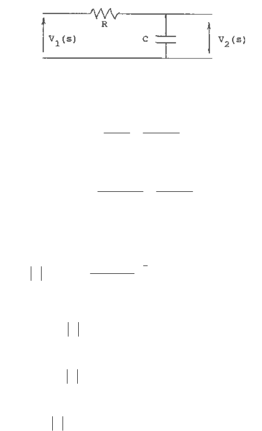
As an example, consider the simple RC filter shown in Figure B.10.
Fig. B.10 An RC filter.
The transfer function of this filter is
1
1
)(
)(
)(
1
2
+
==
RCssV
sV
sG
and the sinusoidal steady-state transfer function is
1
1
1
1
)(
+
=
+
=
ωτω
ω
jRCj
jG (B.54)
where
RC=
τ
, the time constant of the network.
The logarithmic gain is
[]
2
2
1
2
)(1log10
)(1
1
log20log20
ωτ
ωτ
+−=
+
=G (B.55)
For small frequencies, i.e.,
τ
ω
/1<< , the logarithmic gain is
dbG 01log10log20 =−= (B.56)
For large frequencies, i.e.,
τ
ω
/1>> , the logarithmic gain is
ωτ
log20log20 −=G (B.57)
At
τ
ω
/1=
, we have
dbG 01.32log10log20 −=−= (B.58)
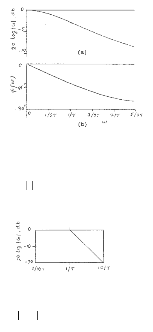
The magnitude plot for this network is shown in Figure B.11a.
The phase angle of this network is
ωτωφ
1
tan)(
−
−=j (B.59)
The phase plot is shown in Figure B.11b. The frequency ω = 1/τ is often called the break
frequnecy or corner frequency.
SELECTED TOPICS FROM CONTROL THEORY
B-16
Fig. B.11 Bode diagram of G(jω) = 1/(1+ jωτ)
A linear scale of frequency is not the most convenient choice in plotting the Bode diagram. A
logarithmic scale of frequency is generally employed. The convenience of a logarithmic scale of
frequency can be seen by considering equation (B.57) for large frequencies,
τ
ω
/1>> , as
follows:
ωτωτ
log20log20log20log20 −−=−=G (B.60)
Then, on a set of axes where the horizontal axis is log ω, the asymptotic curve for
τ
ω
/1>>
is a
straight line as shown in Figure B.12.
Fig. B.12 Asymptotic curve for 1/(1+ jωτ).
A ratio of two frequencies equal to ten is called a decade, so that the difference between the
logarithmic gains, for
τ
ω
/1>> , over a decade of frequency is
(
)
db
GG
20
10
1
log20log20
log20log20)(log20)(log20
2
1
2121
+=−=−=
−−−=−
τω
τω
τωτωωω
(B.61)
That is, the slope of the asymptotic line for this first-order transfer function is −20 db/decade, as
shown in Figure B.12.
References
1. R.C. Dorf, Modern Control Systems, Addison-Wesley Publishing Co. 1967.
2. O.I. Elgerd, Control Systems Theory, McGraw-Hill, N.Y. 1967.
C-1
APPENDIX C
BLOCK DIAGRAM STATE MODEL
The dynamics of a system, in state-space form, are represented by a set of first-order differential
equations in terms of a set of state variables, which in compact form may be represented by a
vector differential equation of the form
uBxAx
+
=
&
(C.1)
as explained in Chapter 2.
It is useful to develop a block diagram state model of the system and use this model to relate the
state variable concept to the transfer function representation.
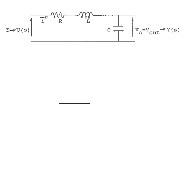
We have seen that a system can be described by an input-output relationship -- the transfer
function G(s). For example, if we are interested in the relationship between the output voltage
and the input voltage of the network shown in Figure C.1, we may obtain the transfer function
Fig. C.1 An R,L,C circuit.
)(
)(
)(
sU
sY
sG =
The transfer function is of the form
γβ
α
++
=
ss
sG
2
)( (C.2)
where α, β and γ are functions of the circuit parameters R, L and C.
The differential equations describing the circuit, choosing state variables
C
Vx =
1
and ix
=
2
, are
2
1
1
x
Cdt
dx
= (C.3)
)(
11
21
2
tu
L
x
L
R
x
Ldt
dx
+−−= (C.4)
The output variable is
1
)( xVty
C
=
= (C.5)
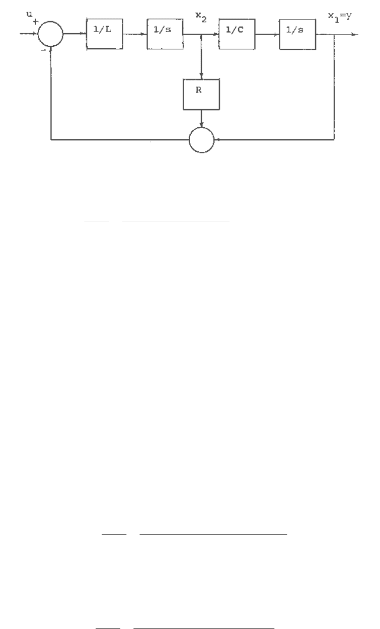
The block diagram representing these simultaneous equations is shown in Figure C.2, where 1/s
indicates an integration
BLOCK DIAGRAM STATE MODEL
C-2
Fig. C.2 Block diagram for the RLC network.
Using the block diagram reduction technique we obtain the transfer function as
)/(1)/(
)/(1
)(
)(
2
LCsLRs
LC
sU
sY
++
= (C.6)
A block diagram state model of a system is useful in that the system differential equations can be
written down directly from the diagram. The diagram may also be recognized as being
equivalent to an analog computer diagram. Also, since there can be more than one set of state
variables describing a system, there can be more than one possible form for the block diagram
state model.
Problem
Draw the block diagram state model for the system described by the following set of equations.
212111
2221212221212
2121112121111
xcxcy
ububxaxax
ububxaxax
+=
+++=
+
+
+
=
&
&
It is often a difficult task to determine a set of first-order differential equations describing the
system. This may be, for example, due to a lack of information concerning the internal structure
of the system and its behavior. Frequently it is simpler to derive the transfer function of a system
or deduce it from the experimentally determined frequency response.
The block diagram state model can be readily derived from the transfer function of a system. In
general, a transfer function may be represented as
01
1
1
01
1
1
)(
)(
)(
asasasa
bsbsbsb
sU
sY
sG
n
n
n
n
m
m
m
m
++++
++++
==
−
−
−
−
L
L
(C.7)
where n ≥ m and all the a and b coefficients are real positive numbers.
In order to illustrate the derivation of the block diagram state model, let us first consider the
fourth-order transfer function
01
2
2
3
3
4
4
1
)(
)(
)(
asasasasa
sU
sY
sG
++++
== (C.8)
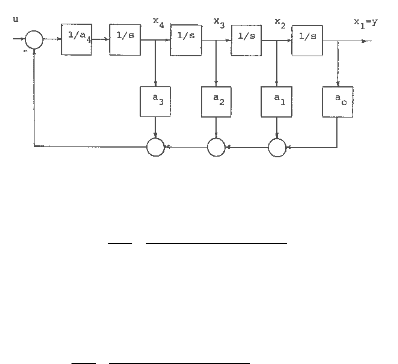
BLOCK DIAGRAM STATE MODEL
C-3
We note that the system is of fourth-order, and hence we will require four state variables.
Choosing the state variables as
ysyx
ysyx
ysyx
yx
3
4
2
3
2
1
==
==
==
=
&&&
&&
&
We can write the differential equations corresponding to the transfer function (C.8) as
4102132434
43
32
21
/)( axaxaxaxaux
xx
xx
xx
−−−−=
=
=
=
&
&
&
&
(C.9)
The block diagram state model corresponding to the above differential equations or the transfer
function of equation (C.8) may therefore be drawn as shown in Figure C.3
Fig. C.3 A block diagram state model for the transfer function of equation C.8.
Next consider the fourth-order transfer function when the numerator is also a polynomial in s so
that
01
2
2
3
3
4
4
01
2
2
3
3
4
4
)(
)(
)(
asasasasa
bsbsbsbsb
sU
sY
sG
++++
++++
== (C.10)
Defining a variable C(s) as
01
2
2
3
3
4
4
)(
)(
bsbsbsbsb
sY
sC
++++
= (C.11)
equation (C.10) can be reduced to
01
2
2
3
3
4
4
1
)(
)(
asasasasa
sU
sC
++++
=
(C.12)
which is of the same form as (C.8).
BLOCK DIAGRAM STATE MODEL
C-4
As before, defining state variables
cscx
cscx
cscx
cx
3
4
2
3
2
1
==
==
==
=
&&&
&&
&
the differential equations corresponding to equation (C.12) will be as in equation (C.9) and the
block diagram state model will be as in Figure C.3.
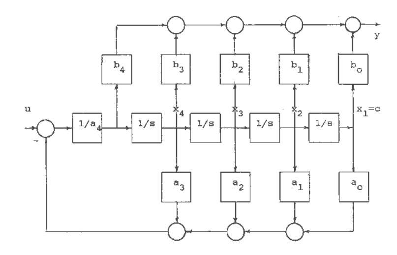
From (C.11)
][)()(
01
2
2
3
3
4
4
bsbsbsbsbsCsY ++++= (C.13)
Therefore, a block diagram state model for the transfer function of equation (C.10) may be
drawn as shown in Figure C.4.
Fig. C.4 A block diagram state model for the transfer function of equation C.10.
A block diagram state model for any of the transfer functions describing the dynamics of the
excitation or governor control systems may be readily obtained from Figures C.3 and C.4.
Examples
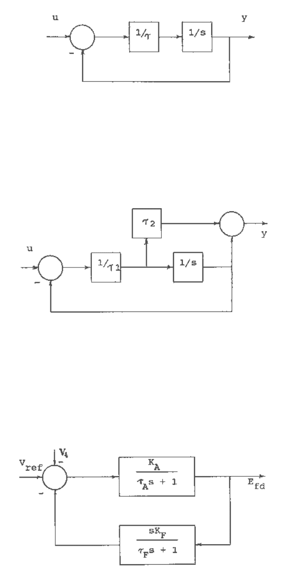
A block diagram model for the transfer function G(s)=1/( τs+1) may be obtained by comparing it
with the transfer function of equation (C.8). The block diagram follows from Figure C.3 and is
shown in Figure C.5.
BLOCK DIAGRAM STATE MODEL
C-5
Fig. C.5 A block diagram state model for transfer function G(s) = 1/( τs + 1).
A block diagram state model for the transfer function
)1/()1()(
12
+
+
=
sssG
τ
τ
may be obtained
by comparing it with the transfer function of equation (C.10). The block diagram follows from
Figure C.4 and is shown in Figure C.6.
Fig. C.6 A block diagram state model for transfer function
)1/()1()(
12
++
=
sssG
τ
τ
.
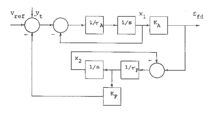
In order to illustrate how easily the set of first-order differential equations describing a system
may be obtained once the transfer function block diagram model has been converted into a state
model, we will consider the excitation control model shown in Figure C.7.
Fig. C.7 Block diagram of an excitation control model.
The state model for the block diagram of Figure C.7 is shown in Figure C.8.
BLOCK DIAGRAM STATE MODEL
C-6
Fig. C.8 A block diagram state model for the system of Fig. C.7.
The set of first-order differential equations for the system is
Ffd
AFfdFtref
xEx
xxEKVVx
τ
τ
τ
/)(
/]/)([
22
121
−=
−
−
−
−=
&
&
References
1. R.C. Dorf, Modern Control Systems, Addison-Wesley Publishing Co.1967.
2. P.M. DeRusso, R.J. Roy and C.M. Close, State Variables for Engineers, Wiley, N.Y. 1965.
