Morris & Fan. Reservoir Sedimentation Handbook
Подождите немного. Документ загружается.

REDUCTION OF SEDIMENT YIELD 12.41
enough (e.g., 24 hours) to make storage space available for the subsequent storm event.
A downward sloping pipe is used to drain the live pool to reduce the potential for
clogging by floating debris, which can be a problem with a horizontal pipe or orifice
(Schueler et al., 1992)
2. Design sedimentation event. Achieve a stated removal efficiency (based on the
surface loading rate) during runoff from the design sedimentation event, with discharge
over the spillway. Design storm intensities ranging from 2- to 10-year events are typically
used in different areas.
3. Design flood. Provide sufficient flood surcharge storage and spillway capacity to
pass the design flood without endangering the structure or causing flood damages.
Selection of the design storm will depend on the size of the structure and its hazard
rating, and in the case of dams (as opposed to excavated ponds), spillway design may be
regulated by state dam safety bodies. The minimum design storm for the spillway rating
would normally be the 100-year event, and in the case of an embankment structure a
much larger event may be appropriate.
4. Dewatering. Provide a low-level outlet for dewatering the basin and its sediment,
to facilitate periodic cleanout. The configuration of the dewatering outlet will depend on
local factors. For example, if coarse sediment is present, it may be advantageous to have
the dewatering drain located at the inlet where the more permeable sediment will
accumulate, instead of at the outlet where the accumulated sediment will be finer and
more difficult to dewater.
The adaptation of this concept to specific areas will depend on local hydrologic and
sediment conditions, plus local regulatory requirements.
12.13.2 Detention Basin Geometry
Detention basin surface area is established from the design sedimentation event and the
surface loading rate. Surface area may also be influenced by the flood and live storage
volumes, which will depend on both the surface area and pool depth. Basin depth is the
sum of freeboard, flood surcharge, live storage, and sediment storage (Fig. 12.17).
Freeboard requirements are usually related to the downstream risks, size of structure,
embankment construction material (e.g., earth or concrete), and in larger structures
factors such as wave action and ice (MacArthur and MacArthur, 1992).
The live storage volume and drainage rate represents a compromise between the
desire to maximize detention time for sedimentation, and the need to empty the live
storage pool quickly to trap a subsequent rainfall event. A water budget model can be
run with 15-minute or hourly rainfall data to analyze basin function, to determine what
percentage of the runoff will be trapped in the live pool. A simplified procedure for this
analysis has been described by Urbonas and Stahre (1993) for hourly rainfall data.
However, these models do not account for the variation in water quality that may occur
over time. According to Urbonas and Stahre (1993), a 24-hour drain time appears to
represent a good compromise between the requirements for sediment trapping and the
desire to empty the basin prior to the subsequent event. As a practical matter, storage
volumes are frequently set by regulatory agencies based on runoff volume.
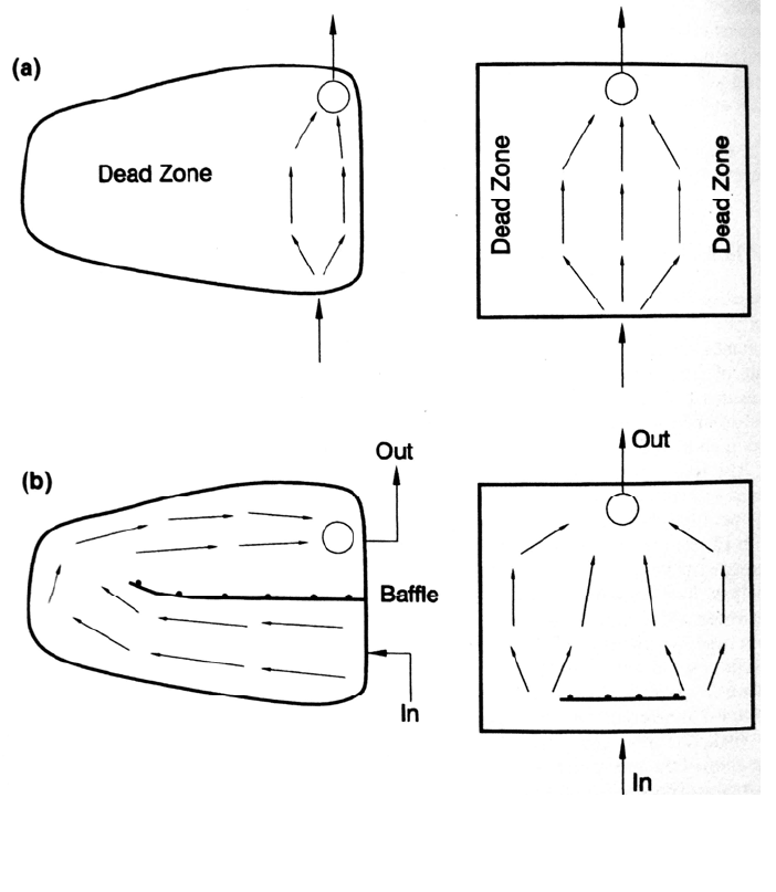
Hydraulic short-circuiting occurs when there are dead zones in the basin, thereby
allowing a portion of the inflow to pass to the basin outlet in a time period less than (or much
less than) the nominal detention period. Discharge entering a basin as a jet from a single inlet
will gradually expand, and at the outlet zone the active flow field constricts in the vicinity of
the discharge weir. An inlet pipe entering a basin and pointing directly at the basin outlet
may effectively short-circuit a large fraction of the basin area. The dead storage volume
REDUCTION OF SEDIMENT YIELD 12.42
in a basin can be quantitatively evaluated by tracer studies in the field, or by physical or
computer modeling. Because of the effort involved, tracer testing and modeling of detention
basins are most suitable for critical sites, or the evaluation or development of standardized
design guidelines or criteria.
The following strategies may be employed to reduce hydraulic short-circuiting within
a settling basin.
Use an elongated basin. Length:width ratios should always exceed 2:1, and larger
values are preferred.
Use interior baffles to extend the effective length:width ratio, and to obstruct the
inflowing jet.
If the basin is triangular in shape, locate the inlet at the narrow end so that the flow
expands with the basin geometry.
The detention basin configurations in Fig. 12.18 illustrate the use of baffles to reducing
hydraulic short-circuiting. However, in a system which has a very accentuated first flush
FIGURE 12.18 (a) Hydraulic short-circuiting in detention basins creates large dead zones. (b)
Use of baffles minimizes the dead zones in the basin. Baffles may be constructed of posts an
d
exterior plywood, roofing panels, heavy plastic, or other water- and wind-resistant material.
REDUCTION OF SEDIMENT YIELD 12.43
effect, such as runoff from a paved area, it may be desirable to trap the first-flush water in
the live storage, and hydraulically short-circuit the cleaner discharge from the
remainder of the event to the flood discharge outlet.
The volume and depth of the sediment storage pool are based on the anticipated
sediment loading rate and the planned period between sediment removal. At a
construction site with potentially high rates of sediment yield, the basin may be cleaned
several times a year or after a major storm. In a developed urban area, where the basin is
incorporated into project landscaping and may support a wetland habitat, the dewatering
and cleaning interval should be on the order of several years or longer. In a wet basin, leave
a minimum water depth of 0.6 m between the top of the design sediment storage pool and
the normal pool level.
Shallow areas in a wet detention pond will become colonized by wetland plants,
either by design or as a result of natural processes, and detention areas can serve as
wetland habitat. Wetland design in stormwater systems has been reviewed by Kadlec and
Knight (1995) and Schueler (1993). In determining the water depths in detention areas,
the colonization depth of wetland vegetation must be taken into consideration. For
instance, cattail (Typha domingensis), a common, aggressive, and less-desirable
wetland plant, can colonize water to depths on the order of 1 m. Depths greater than this
may be required to maintain open water unless vegetative control efforts are undertaken.
12.13.3 Design Computations for Plug Flow
Sediment retention ponds are subject to widely varying rates of inflow, and the settling
characteristics of the inflowing sediments may change as a function of season, and over
longer periods of time because of land use change. The extent of hydraulic short-
circuiting will normally be unknown, and may also change over time as trapped sediments
accumulate and vegetation grows, altering storage volume and other hydraulic
characteristics. As a result, engineering procedures for sedimentation pond design
provide only a rough approximation of actual performance.
Inflow Hydrology. To size the basin surface area and the flood spillway, the inflow
must be estimated for the design sedimentation event as well as the spillway design
discharge. For small basins, simple procedures can be used—for example, the rational
formula, which has the form:
Q = CIA (12.1)
where Q = discharge (m
3
/s, ft
3
/s), I = rainfall intensity (m/s, in/h) for a duration equal to
the time of concentration for the tributary drainage area, A = tributary drainage area (m
2
,
acres), and C = dimensionless runoff coefficient, which is the same in either system of
units. Representative coefficient values are given in Table 12.5. Local hydrologic design
guidelines may adopt other values.
Sediment detention structures may also be used for flood detention, in which case the
outlet structure should be designed with unsteady-flow modeling tools to generate and
route stormwater hydrographs. Many stormwater modeling tools are available from
commercial software vendors, which are suitable for performing runoff and hydraulic
routing computations in detention ponds.
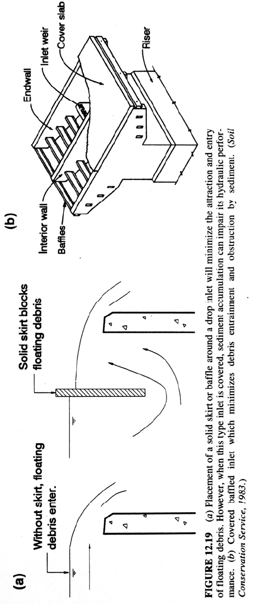
Drop inlet spillways will draw down the water level in the vicinity of the weir, which
tends to attract floating debris. Placement of a solid skirt or baffle around the inlet,
which extends above and below the weir crest (Fig. 12.19a), will minimize the problem
of debris entrainment. The inlet top may then be covered. However, sediment deposition
can encroach on the flow area below the inlet. Use of a baffled inlet structure

REDUCTION OF SEDIMENT YIELD 12.44
(Fig.12.19b) which minimizes this problem is described by the Soil Conservation Service
(1983).
TABLE 12.5 Representative Coefficient Values for Rational Formula
Type of drainage area Runoff coefficient, C
Lawns:
Sandy soil, flat, 2% 0.05-0.10
Sandy soil, average, 2-7% 0.10-0.15
Sandy soil, steep, 7% 0.15-0.20
Heavy soil, flat, 2% 0.13-0.17
Heavy soil, average, 2-7% 0.18-0.22
Heavy soil, steep, 7% 0.25-0.35
Business:
Downtown areas 0.70-0.95
Neighborhood areas 0.50-0.70
Residential:
Single-family areas 0.30-0.50
Multi units, detached 0.40-0.60
Multi units, attached 0.60-0.75
Suburban 0.25-0.40
Apartment dwelling areas 0.50-0.70
Industrial:
Light areas 0.50-0.80
Heavy areas 0.60-0.90
Parks, cemeteries 0.10-0.25
Playgrounds 0.20-0.35
Railroad yard areas 0.20-0.40
Unimproved areas 0.10-0.30
Streets:
Asphaltic 0.70-0.95
Concrete 0.80-0.95
Brick 0.70-0.85
Drives and walks 0.75-0.85
Roofs 0.75-0.95
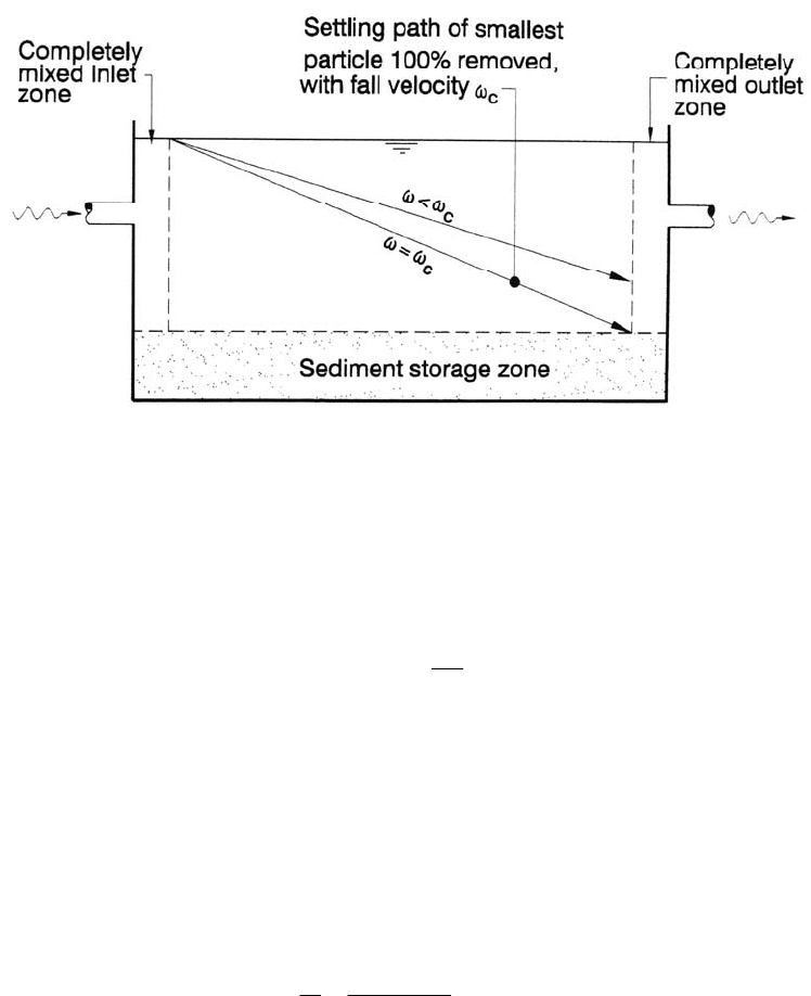
Determine Pond Surface Area. The quiescent sedimentation of discrete particles
within an idealized rectangular settling tank can be conceptualized by using the diagram
in Fig. 12.20. The basin's inlet and outlet zones are considered to be completely mixed.
The critical fall velocity ω
c
in this basin is the fall velocity of the smallest-size-class
(slowest-settling) particle which will be completely removed by plain sedimentation, as
illustrated in the figure. All particles with a higher fall velocity will also be completely
removed. The critical settling velocity ω
c
of the smallest-size-class particle that is 100
percent sedimented in the idealized basin is given by:
c
Q
A
b
(12.2)
where Q = discharge and A
b
= basin surface area. The ratio Q/A
b
(the surface loading
rate) indicates that sediment removal is dependent on the surface area of the settling
basin, but not its depth.
REDUCTION OF SEDIMENT YIELD 12.45
REDUCTION OF SEDIMENT YIELD 12.46
FIGURE 12.20 Particle settling in an idealized sedimentation basin.
ln
flowing sediment load exhibits a range of grain sizes and settling velocities, and
particles in size classes with a fall velocity less than the critical fall velocity (ω < ω
c
) will
be only partially removed. The trapping efficiency E of this slower-settling sediment is
given by the ratio of settling velocities:
c
E
(12.3)
where ω = fall velocity of the particles in a class size where <
c
.
The surface loading rate and the trap efficiency as a function of the inflowing grain
size distribution may be used to determine the sediment removal and, from this, the
grain size distribution of released sediment in the effluent. Sediment trapping
computations for an idealized sedimentation basin are illustrated in the following
example for a 1-ha (10,000 m
2
) basin with an inflow rate of 1 m
3
/s, water temperature of
20°C, and the inflowing grain size distribution given in Fig. 12.21.
1. Compute the surface loading rate to determine the settling velocity of the slowest-
settling particle size class that will be 100 percent removed:
c
Q
A
1m
3
/s
10,000m
2
110
4
m/s
The particle diameter d, corresponding to the critical settling velocity
c
is estimated
at 0.0105 mm by the Rubey equation [Eq. (5.23)].
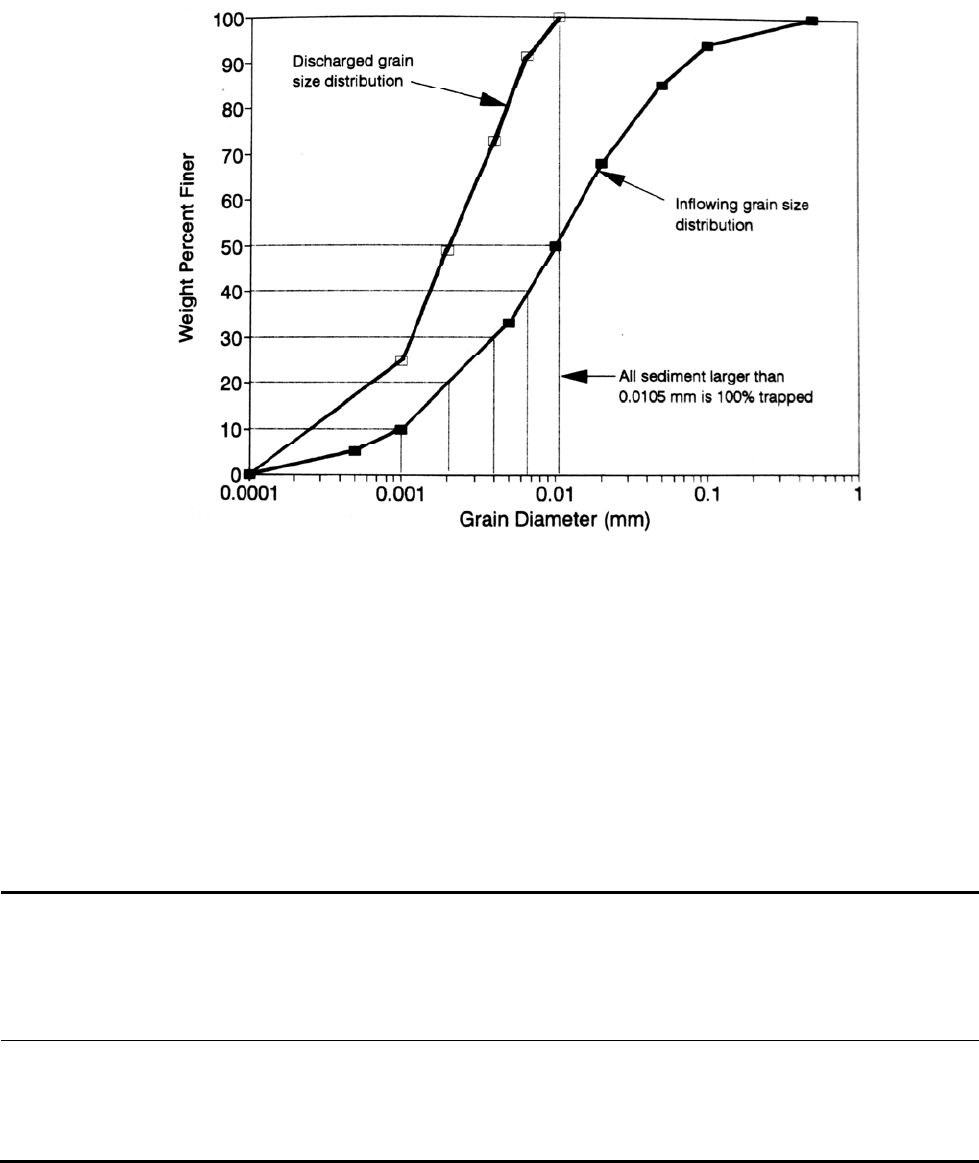
2. Referring to the inflowing grain size distribution, subdivide the particles smaller
than d into classes, as shown in Fig 12.21, and determine the mean settling velocity
for each class.
3. Compute the trap efficiency for each sediment size class as E = /
c
For the
inflowing sediment with settling velocity greater than
c
the trap efficiency will
be 100 percent (i.e., E = 1). Compute release efficiency as 1 - E.
4. Compute the overall trap efficiency for the inflowing sediment load by multiplying
the weight percent in each class by the corresponding trap efficiency for each class,
and summing.
REDUCTION OF SEDIMENT YIELD 12.47
FIGURE 12.21 Inflow and outflow suspended-sediment grain size distribution for example detention
basin computations. The dotted lines indicate the grain size class intervals for the portion of the
inflowing sediment load with a trap efficiency of less than 100 percent.
5. C
ompute the size distribution in the water discharged from the basin, as
illustrated in Fig. 12.21.
Numerical computations for this example problem are summarized in Table 12.6. In the
example basin, all sand and coarse silt is completely trapped, but the trapping rate of
clays is insignificant. This procedure can be modified to size a basin to achieve a given
level of removal efficiency given the inflowing grain size distribution.
TABLE 12.6 Sediment Trapping Computations for an Idealized Detention Basin
Cumulat
ive
Me
an Mean Se
diment
Fa
ll
Class
interval,
weight
%
Class Lower Upper Re
lease Release
Cla
ss Class
Velocity
Size, Particle
Diameter,
Particle Particle Call E
fficiency By class
Ratio
We
ight
%
Diameter, By
class, % of
Di
ameter, Velocity,
mm mm mm m/s /
c
decimal inflow
Released
Sediment
Grain
Size
Distribution,
% finer
0-10 10 0.0001 0.0010 0.0006 3.2 × 10
-7
0.003 0.997 9.97 25
10-20 10 0.0010 0.0020 0.0015 2.0 × 10
-6
0.020 0.980 19.77 49
20-30 10 0.0020 0.0040 0.0030 3.6 × 10
-6
0.036 0.964 29.41 73
30-40 10 0.0040 0.0065 0.0053 2.5 × 10
-5
0.250 0.750 36.91 91
40-50 10 0.0065 0.0105 0.0085 6.5 × 10
-5
0.650 0.350 40.41 100
REDUCTION OF SEDIMENT YIELD 12.48
12.13.4 Sedimentation under Turbulent Nonidealized Conditions
Real basins are not plug flow reactors, and even basins designed to optimize
sedimentation may have a significant volume of dead space and secondary currents
circulating within the basin. Under turbulent and nonideal conditions, the trap efficiency
as a function of the settling velocity ratio who, can be given by (Urbonas and Stahre,
1993):
n
c
n
E
1
11
(12.4)
where E = trap efficiency of sediment in the size class corresponding to particle fall
velocity , n = a factor which depends on the hydraulic efficiency of the basin, and
c
=
critical fall velocity as defined in Fig. 12.20. Suggested values of n, based on settling
characteristics, are
n = I Poor settling characteristics
n = 3 Good performance
n>5 Very good performance
n = infinity Ideal performance
For very large values of n, this equation reduces to the equation for idealized
sedimentation under turbulent conditions:
E
1
e
/
c
(12.5)
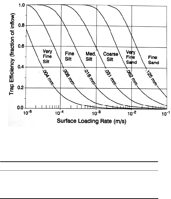
A graph of settling characteristics as a function of grain size for n = 3 (good
performance) is provided in Fig. 12.22 and may be used to estimate the removal
efficiencies. The difference between good and poor performance has a relatively small
impact on the settling curve in the area of low removal efficiencies ( much less than
c
), but significantly affects the removal of particles with settling velocities close to the
critical velocity
c
12.13.5 Dewatering Orifice
The discharge orifice should be sized to dewater the live storage zone within a stated time
period, such as 24 hours. The discharge rate through an orifice is given by:
Q CA 2gh (12.6)
where: C = orifice coefficient
A = orifice area (m
2
, ft
2
)
g = gravitational constant (m/s
2
, ft/s
2
)
h = head above the orifice (m, ft)
This equation is dimensionally consistent and the orifice coefficient is independent of the
system of units. Several orifice coefficient values are given in Table 12.7.
As the pond dewaters the orifice will operate under continuously decreasing head. For
a basin with vertical sides and zero inflow during the dewatering period, the time
required to dewater the volume above the orifice may be determined by using a
discharge rate equal to half the discharge at the maximum head (i.e., Q
max
/2). The time
required to dewater a basin through an orifice can also be given by:
T
B 2h
3600AC g
(12.7)
REDUCTION OF SEDIMENT YIELD 12.49
TABLE 12.7 Orifice Coefficient Values
Condition
FIGURE 12.22 Settling characteristics as a function of grain size for estimating the
efficiency of a settling basin with "good" hydraulic characteristics [n = 3 in Eq. (12.4)].
Coefficient C
Sharp edge, circular or square 0.6
Short tube (length = 2 or 3 times diameter)
flush with wall 0.82
inward projecting 0.75
Borda's mouthpiece (length = 'A diameter) 0.51
Source: King and Brater (1963).
where T = time to dewater (hours), B = basin surface area, and h = initial head above the
orifice (Goldman et al., 1986).
12.13.6 Weir Discharge
Horizontal weirs are often used to discharge floodwater from detention structures. The
general equation for discharge over a horizontal broad-crested weir is
Q
CLH
3/2
(12.8)

REDUCTION OF SEDIMENT YIELD 12.50
where: Q = discharge (m
3
/s, ft
3
/s)
L = length of the weir (m, ft)
H = head upstream of the weir (m, ft)
The value of the coefficient C depends on the weir geometry and the system of units.
Coefficient values may be converted between SI units and the fps system by
C
SI
= C
fps
/ 1.81
Coefficient values for broad-crested weirs are summarized in Table 12.8, where the
breadth of the weir crest is measured parallel to the direction of flow.
TABLE 12. 8 Coefficient Values for Broad-Crested Weirs
Head
(ft)
0.5 0.75 1 1.5
Breadth (ft)
2 2.5
3 4 5 10 15
0.2 2.80 2.75 2.69 2.62 2.54 2.48 2.44 2.38 2.34 2.49 2.68
0.4 2.92 2.80 2.72 2.64 2.61 2.60 2.58 2.54 2.50 2.56 2.70
0.6 3.08 2.89 2.75 2.64 2.61 2.60 2.68 2.69 2.70 2.70 2.70
1.0 3.32 3.14 2.98 2.75 2.66 2.64 2.65 2.67 2.68 2.68 2.63
2.0 3.32 3.31 3.30 3.03 2.85 2.76 2.72 2.68 2.65 2.64 2.63
3.0 3.32 3.32 3.32 3.32 3.20 3.05 2.92 2.73 2.66 2.64 2.63
5.5 3.32 3.32 3.32 3.32 3.32 3.32 3.32 3.32 2.88 2.64 2.63
Breadth (m)
Head
(m) 0.15 0.23 0.30 0.46 0.61 0.76 0.91 1.22 1.52 3.05 4.57
0.06 1.55 1.52 1.49 1.45 1.40 1.37 1.35 1.31 1.29 1.38 1.48
0.12 1.61 1.55 1.50 1.46 1.44 1.44 1.43 1.40 1.38 1.41 1.49
0.18 1.70 1.60 1.52 1.46 1.44 1.44 1.48 1.49 1.49 1.49 1.49
0.30 1.83 1.73 1.65 1.52 1.47 1.46 1.46 1.48 1.48 1.48 1.45
0.61 1.83 1.83 1.82 1.67 1.57 1.52 1.50 1.48 1.46 1.46 1.45
0.91 1.83 1.83 1.83 1.83 1.77 1.69 1.61 1.51 1.47 1.46 1.45
1.68 1.83 1.83 1.83 1.83 1.83 1.83 1.83 1.83 1.59 1.46 1.45
Source: King and Brater (1963).
12.14 DEBRIS BASINS
Debris basins are designed primarily to trap coarse sediment which would otherwise
cause objectionable deposits in channels or other downstream areas. They may also be
used to trap hyperconcentrated debris flows originating in mountainous areas.
12.14.1 Debris Basin Configurations
Debris basins may be constructed as conventional dams with overflow spillways, as
basins equipped with perforated risers, as dams with a permanently open sluice, or as
excavated pits in the streambed. For hyperconcentrated debris flows, there are additional
techniques for protecting downstream areas, such as construction of channels and protective
walls. Several strategies for protection against hyperconcentrated debris flows are
illustrated in Fig. 12.23. Stonestreet (1994) and Gist et al. (1996) describe the design of a
series of excavated pools for use for trapping of floodborne debris on San Timoteo Creek