Mattingly J.D., Heiser W.H., Pratt D.T. Aircraft Engine Design
Подождите немного. Документ загружается.

540 AIRCRAFT ENGINE DESIGN
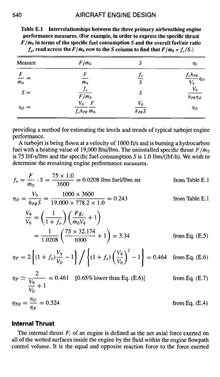
Table E.1 Interrelationships between the three primary airbreathing engine
performance measures. (For example, in order to express the specific thrust
F/rho
in terms of the specific fuel consumption S and the overall fuel/air ratio
fo,
read across the
F/~no
row to the S column to find that
F/mo = fo/S.)
Measure
F l rno S rio
F F
fo fohpR
mo rno S Vo Oo
S= fo S Vo
Fl~no
hpRriO
Vo F Vo
rio = foheR #lo
hpRS
riO
providing a method for estimating the levels and trends of typical turbojet engine
performance.
A turbojet is being flown at a velocity of 1000 ft/s and is burning a hydrocarbon
fuel with a heating value of 19,000 Btu/Ibm. The uninstalled specific thrust F/rh0
is 75 lbf-s/lbm and the specific fuel consumption S is 1.0 lbm/(lbf-h). We wish to
determine the remaining engine performance measures.
F 75 x 1.0
fo = -- • S - -- -
0.0208 Ibm fuel/Ibm air from Table E.1
rh0 3600
V0 1000 x 3600
Oo -- -- -- = 0.243 from Table E.1
heRS
19,000 x 778.2 × 1.0
Voo = \moVo +1
1(75×32.174)
-- 1.0208 1000 + 1 = 3.34 fromEq. (E.5)
I T-~
}/{ (V9~2 }
=2 (l+fo) v0-1 (l+fo)\v00,/ -1 =0.464 fromEq.(E.6)
0P
2
0P --~ V9 = 0.461 [0.65% lower than Eq. (E.6)] from Eq. (E.7)
+
1
v0
0o
~Tr~/-- -- 0.524 from Eq. (E.4)
r/p
Internal Thrust
The internal thrust
Fi
of an engine is defined as the net axial force exerted on
all of the wetted surfaces inside the engine by the fluid within the engine flowpath
control volume. It is the equal and opposite reaction force to the force exerted
APPENDIX E: ENGINE EFFICIENCY AND THRUST MEASURES541
on that fluid. The sign convention is that
Fi
is positive when it acts in the di-
rection of flight (i.e., opposite to the direction of the freestream flow). Because
the fuel and bleed airflows may be assumed to have negligible axial momen-
tum when they cross their respective control volume boundaries, they contribute
nothing to the internal thrust. The impulse function of Sec. 1.9.5 may there-
fore be applied directly to show that the internal thrust is given by the simple
expression
Fi = 19 - 11
(E.8)
The internal engine thrust
Fi
may be easily evaluated from quantities provided by
ONX or AEDsys by means of Eq. (E.8).
Uninstalled Thrust
The uninstalled thrust F of an engine is an extremely useful engineering ide-
alization that allows all parties concerned to communicate about this important
property with clarity and precision. It is also the primary thrust measure used in
this textbook. The uninstalled thrust F is defined as the net axial force that would
be produced by an engine immersed in a perfect or inviscid external flow. It is
equal and opposite to the force exerted on all of the fluid influenced by the engine
and is positive when it acts in the direction of flight. The derivation of the relation-
ships governing uninstalled thrust is greatly simplified by the careful selection of
appropriate control volumes.
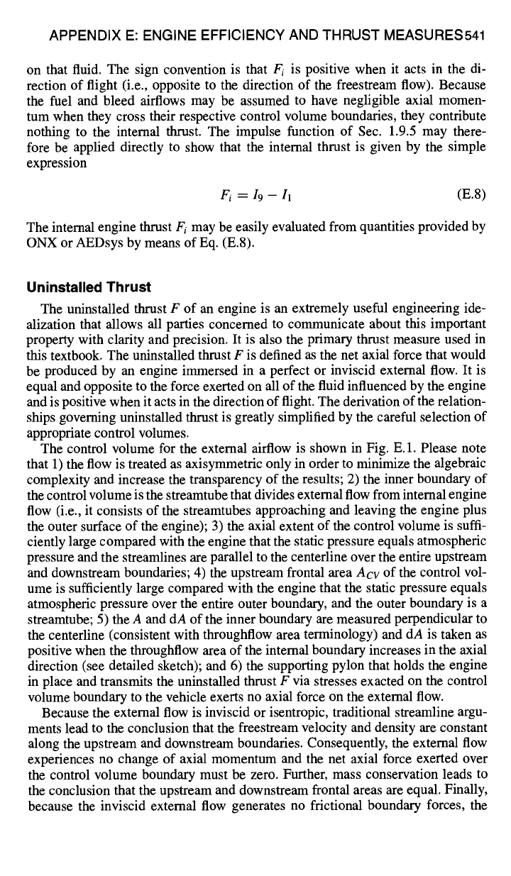
The control volume for the external airflow is shown in Fig. E. 1. Please note
that 1) the flow is treated as axisymmetric only in order to minimize the algebraic
complexity and increase the transparency of the results; 2) the inner boundary of
the control volume is the streamtube that divides external flow from internal engine
flow (i.e., it consists of the streamtubes approaching and leaving the engine plus
the outer surface of the engine); 3) the axial extent of the control volume is suffi-
ciently large compared with the engine that the static pressure equals atmospheric
pressure and the streamlines are parallel to the centerline over the entire upstream
and downstream boundaries; 4) the upstream frontal area
Acv
of the control vol-
ume is sufficiently large compared with the engine that the static pressure equals
atmospheric pressure over the entire outer boundary, and the outer boundary is a
streamtube; 5) the A and dA of the inner boundary are measured perpendicular to
the centerline (consistent with throughflow area terminology) and dA is taken as
positive when the throughflow area of the internal boundary increases in the axial
direction (see detailed sketch); and 6) the supporting pylon that holds the engine
in place and transmits the uninstalled thrust F via stresses exacted on the control
volume boundary to the vehicle exerts no axial force on the external flow.
Because the external flow is inviscid or isentropic, traditional streamline argu-
ments lead to the conclusion that the freestream velocity and density are constant
along the upstream and downstream boundaries. Consequently, the external flow
experiences no change of axial momentum and the net axial force exerted over
the control volume boundary must be zero. Further, mass conservation leads to
the conclusion that the upstream and downstream frontal areas are equal. Finally,
because the inviscid external flow generates no frictional boundary forces, the
542 AIRCRAFT ENGINE DESIGN
Acv
Control Volume
Streamline • Vo _~__ Boundary ....
I- "1
I
!
i
!
!
~-~o ~ ,, .~ v0
I I PYLON I A
A=IA(x)
[ I ,~-- P =,(x) ', ~
~, __.~ ....... ~_~ .__.
,
_'.-_---.2 .... [_ ........... I ......... ~_...x
.... -,----%.._ ENO,NE J.
. ~-~'~ - ~-'~' ~ ........ oo
| , - ~ 9
,~ Vo '~Vo
Streamline
• go
Fig. E.1
Control
Volume ~ j~
Boundary ~ ~. ~,,~
dA >O
I ~ - ~ ~-I
t
.............. -CL-..~x
Detail
Control volume for
the engine external airflow.
condition of perfect external flow requires that the axial pressure integral over the
control volume boundary of Fig. E. 1 be zero, or
PoAcv + Po(A~ - Ao) - PoAcv
- P dA = 0 (E.9)
or, since fo dA
= A~ - A0,
then
f0
~(P - Po)dA = (E.10) 0
APPENDIX E: ENGINE EFFICIENCY AND THRUST MEASURES543
I~ PYLON Control Volume
] [ /Boundary
A
- A(x)
F., I I I P = P(x) x'7
:--I- " ............ 2i
....
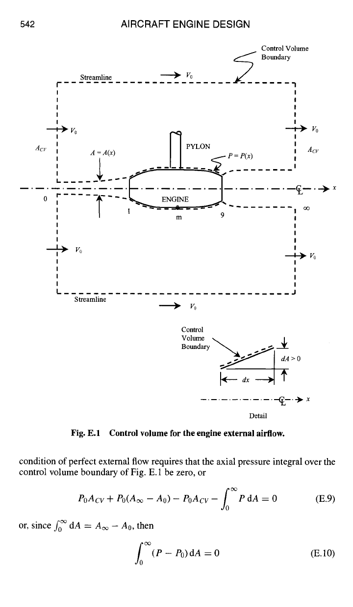
Fig. E.2 Control volume for evaluating uninstalled engine thrust.
This interesting and universal result reveals that the axial area average of the
pressure P over the internal boundary must be equal to P0 for perfect external
flows.
The control volume for evaluating the uninstalled thrust is shown in Fig. E.2.
The same rules as those of Fig. E.1 and Sec. 1.9.5 apply, except that the divid-
ing streamtube is the outer boundary for this case. Assuming that the fuel and
bleed airflows contribute no axial momentum, the axial direction control volume
momentum analysis yields
5
F + PdA = I~ - Io
(E.11)
The nature of the free exhaust jet is such that the ambient static pressure is impressed
essentially over its entire external surface. Thus, applying control volume analysis
separately to the exhaust stream downstream of the exit plane, we find that
I~ = 19 + Po(A~ -
A9) (E.12)
Finally, Eqs. (E. 10-E. 12) and fo dA = A~- A0 are combined to yield the desired
expression for the uninstalled thrust:
1
F = 19 - I0 - P0(a9 - a0) = --(rh9V9 - rn0V0) -I- A9(P9 - P0) (E.13)
go
Equation (E.13), which is identical to Eq. (4.1), allows the uninstalled thrust F
to be easily evaluated from quantities provided by ONX or AEDsys. Because the
uninstalled thrust depends only upon flow quantities governed by cycle parameters,
it is an inherent property of the engine cycle, is independent of installation effects,
and is used as the standard of engine performance.
Installed Thrust
Because the external flow is actually viscous and imperfect, there is a down-
stream axial drag on the engine control volume equal and opposite to the upstream
axial drag on the external flow control volume (see Figs. E.1 and E.2). Thus,
the installed thrust T must be equal to the uninstalled thrust F minus this drag.
The drag is due both to frictional stresses acting along the dividing streamtube
(primarily the boundary layer on the outer surface of the engine) and to pressure or
544 AIRCRAFT ENGINE DESIGN
form drag resulting from boundary layer separation (caused either by adverse pres-
sure gradients or by shock-boundary layer interactions). Because the frictional drag
is included in the vehicle account, engine designers are responsible only for the
pressure drag.
The pressure drag is variously referred to as the installation or integration "drag,"
"penalty," or "effect" in the literature. Because the pressure drag obviously depends
on the entire shape of the dividing streamtube, it also depends on the flight condi-
tions and the engine throttle setting (e.g., A0 and A9) and is therefore deservedly
referred to also as the "throttle-dependent drag." Several specific examples of in-
stallation drag are provided in Sec. 6.2. The following material provides a general
introduction to the analysis of installation drag as well as the background necessary
for the design work of this textbook.
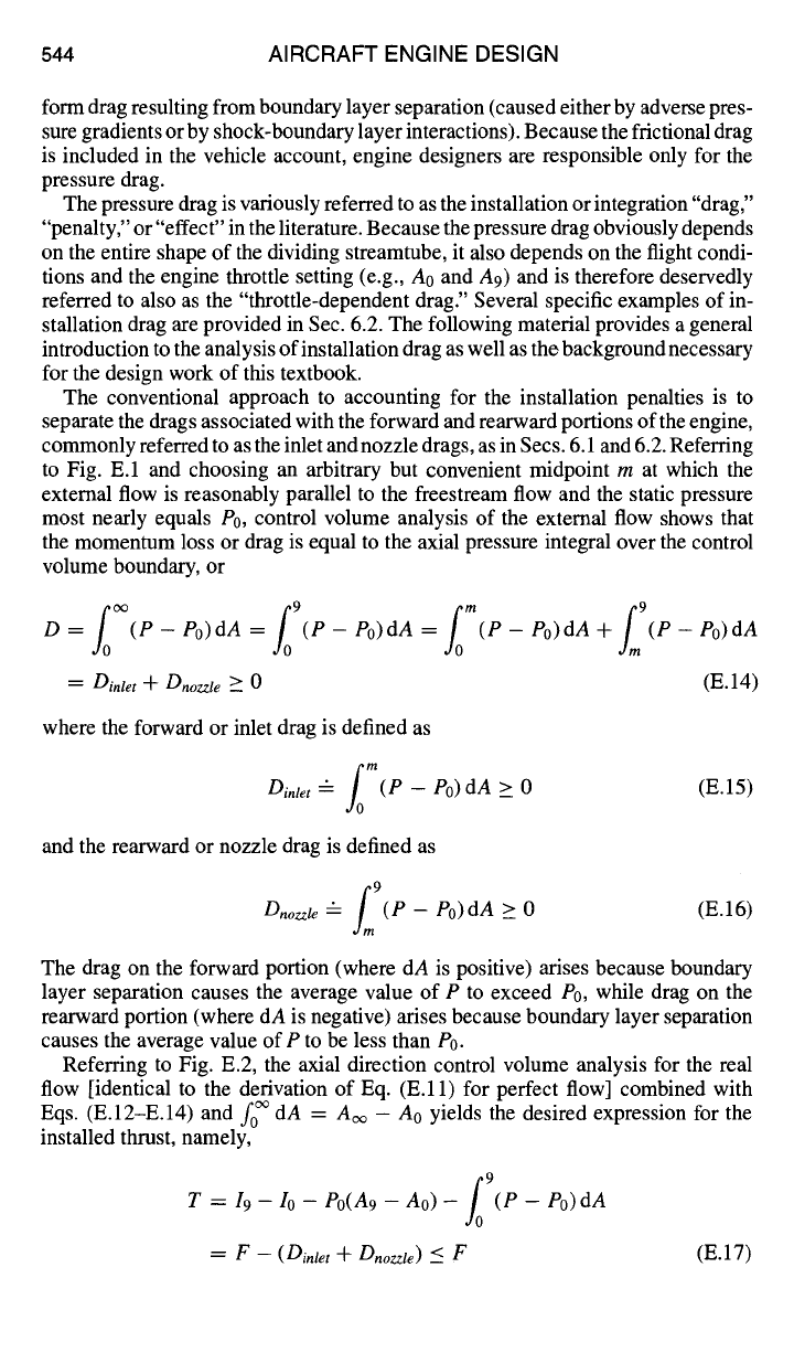
The conventional approach to accounting for the installation penalties is to
separate the drags associated with the forward and rearward portions of the engine,
commonly referred to as the inlet and nozzle drags, as in Secs. 6.1 and 6.2. Referring
to Fig. E.1 and choosing an arbitrary but convenient midpoint m at which the
external flow is reasonably parallel to the freestream flow and the static pressure
most nearly equals P0, control volume analysis of the external flow shows that
the momentum loss or drag is equal to the axial pressure integral over the control
volume boundary, or
L °° L 9 L m S;
D = (P - Po)dA = (P - Po)dA = (P - Po)dA + (P - Po)dA
= Dinlet -'}- Dnozzle >_ 0
(E.14)
where the forward or inlet drag is defined as
L °
Dirtier --
(P --
P0)dA > 0 (E.15)
and the rearward or nozzle drag is defined as
L 9
Dnozzte -- (P -
P0)dA > 0 (E.16)
The drag on the forward portion (where dA is positive) arises because boundary
layer separation causes the average value of P to exceed Po, while drag on the
rearward portion (where dA is negative) arises because boundary layer separation
causes the average value of P to be less than P0.
Referring to Fig. E.2, the axial direction control volume analysis for the real
flow [identical to the derivation of Eq. (E.11) for perfect flow] combined with
Eqs. (E.12-E.14) and fo dA = A~ - A0 yields the desired expression for the
installed thrust, namely,
/0 9
T =/9 - Io - Po(A9 - Ao) - (P - Po)dA
= F
- (Dinlet + Dnozzle)
<_ F
(E.17)
APPENDIX E: ENGINE EFFICIENCY AND THRUST MEASURES545
Equation (E. 17) is not only a very practical result, but it is also rich with meaning.
Two of the most important messages are that designers require the means to evaluate
Dinlet
and Dnozzle
in order to derive T from F, and that T is directly dependent
upon installation effects and therefore should not be used as a standard of engine
performance.
Ground Test Determination of Uninstalled Thrust
One practical difficulty with the uninstalled thrust is that there is no way to
measure this idealized quantity directly in a ground test facility. In particular, F is
not equal to the force exerted on the test facility thrust stand, usually referred to
as the scale force Fs. Because the correct determination of the uninstalled thrust
is of paramount importance to aircraft and engine designers and their customers,
the process of deriving F from F, is described next. It is important to note that
because the real engine inlet and exhaust flows are nonuniform, integral methods
must be used in place of the one-dimensional approach. Nevertheless, the integral
impulse function retains its original significance, namely, that the net axial force
exerted on the fluid flowing through a control volume is the difference between
the exit and inlet impulse functions (see Sec. 1.9.5).
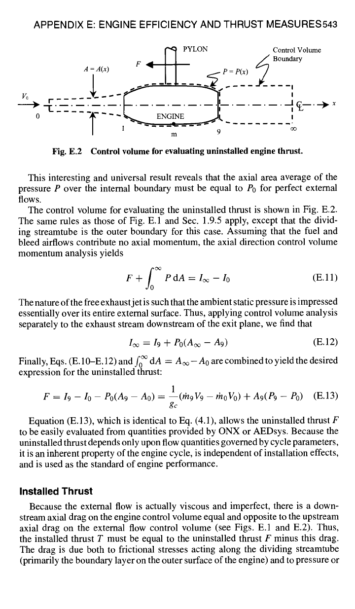
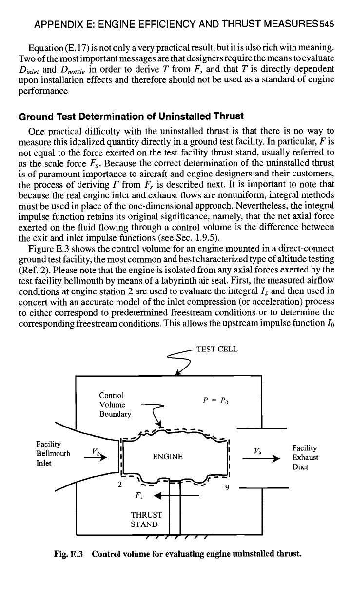
Figure E.3 shows the control volume for an engine mounted in a direct-connect
ground test facility, the most common and best characterized type of altitude testing
(Ref. 2). Please note that the engine is isolated from any axial forces exerted by the
test facility bellmouth by means of a labyrinth air seal. First, the measured airflow
conditions at engine station 2 are used to evaluate the integral I2 and then used in
concert with an accurate model of the inlet compression (or acceleration) process
to either correspond to predetermined freestream conditions or to determine the
corresponding freestream conditions. This allows the upstream impulse function I0
~
TEST CELL
Control
Volume ~ P = P0
~l Boundary k
Facility -"71 [''~ ~"l I
Be.mouth % I'1 ENO E
I',
Inlet
" ---ill ~ ~ II
THRUST
~ ST A~ID
....
V9 Facility
~.. Exhaust
Duct
Fig. E.3 Control volume for evaluating engine uninstalled thrust.
546 AIRCRAFT ENGINE DESIGN
to be evaluated. Next, the facility exhaust system is used to set the static pressure
surrounding the engine and nozzle exit station 9 equal to the freestream static
pressure P0. Finally, the axial direction control volume analysis is used to show
that
19 = 12 -t- Fs +
P0(A9
--
A2) (E.18)
where 12 and 19 are integrated impulse functions, F~ is the scale force measured by
the thrust stand, and 12 is obtained from station 2 measurements as just described.
Two types of corrections are required before Eq. (E. 18) can provide a sufficiently
accurate value for 19 at a specific test condition. First, test cell calibrations must be
used to reduce or eliminate such deterministic errors in
Fs
as test stand and load
cell ambient pressure and temperature effects, aerodynamic and mechanical tares,
test cell static pressure distribution forces (buoyancy), and the consequences of
leakage flows. Second, empirical relationships in the form of influence coefficients
must be applied to adjust 19 for differences between the desired and actual test cell
conditions and engine control settings. An interesting observation is that, because
the state of the flow at station 2 can be quite far from freestream conditions, F~
can be zero or less.
The expression for the uninstalled thrust is obtained by combining Eqs. (E. 13)
and (E. 18) in order to yield the desired relationship
F = F~ + (12 - I0) - P0(A2 - A0) (E.19)
Modem, highly developed, direct-connect ground test facilities use this process
to provide uninstalled thrust measurements with an uncertainty in the range of
+/- 0.5 to 1.0%, depending on the engine configuration and flight conditions.
You may well imagine how much more difficult the determination of F must be in
flight testing. The close control over simulated flight conditions, large amounts and
variety of data, excellent accuracy of results, and reduced risk to personnel make
ground testing the approach overwhelmingly employed for engine development.
References
IOates, G. C.,
The Aerothermodynamics of Gas Turbine and Rocket Propulsion,
3rd ed.,
AIAA Education Series, AIAA, Reston, VA, 1997.
2Smith, R. E., Jr., and Wehofer, S., "Measurement of Engine Thrust in Altitude Ground
Test Facilities," AIAA Paper 82-0572, 1982.
Appendix F
Compressible Flow Functions for Gas
with Variable Specific Heats
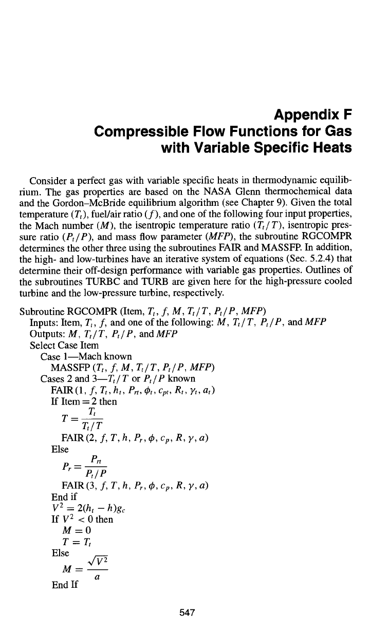
Consider a perfect gas with variable specific heats in thermodynamic equilib-
rium. The gas properties are based on the NASA Glenn thermochemical data
and the Gordon-McBride equilibrium algorithm (see Chapter 9). Given the total
temperature (Tt), fuel/air ratio (f), and one of the following four input properties,
the Mach number (M), the isentropic temperature ratio (Tt/T), isentropic pres-
sure ratio (Pt/P), and mass flow parameter (MFP), the subroutine RGCOMPR
determines the other three using the subroutines FAIR and MASSFP. In addition,
the high- and low-turbines have an iterative system of equations (Sec. 5.2.4) that
determine their off-design performance with variable gas properties. Outlines of
the subroutines TURBC and TURB are given here for the high-pressure cooled
turbine and the low-pressure turbine, respectively.
Subroutine RGCOMPR (Item, Tt, f, M, Tt/ T, Pt/ P, MFP)
Inputs: Item, Tt, f, and one of the following: M, Tt/T, Pt/P, andMFP
Outputs: M, Tt/ T, Pt/ P, and MFP
Select Case Item
Case 1---Mach known
MASSFP (Tt, f, M, Tt/T, Pt/P, MFP)
Cases 2 and 3--Tt/T or Pt/P known
FAIR(l, f, Tt , ht, Prt, (at, Cpt, Rt , Yt , at)
If Item = 2 then
T,
T--
T,/T
FAIR (2, f, T, h, Pr , (b , c p , R, y, a)
Else
Pr~
Pr--
t', / e
FAIR (3, f, T, h, Pr, ~b, Cp, R, V, a)
End if
V 2 = 2(ht - h)gc
If V 2 < 0 then
M=0
T = Tt
Else
M--
a
End If
547
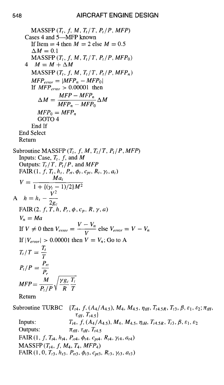
548 AIRCRAFT ENGINE DESIGN
MASSFP
(Tt, f, M, Tt/T, Pt/P, MFP)
Cases 4 and 5--MFP known
If Item = 4 then M = 2 else M = 0.5
AM = 0.1
MASSFP
(Tt, f, M, Tt/T, Pt/P, MFPo)
4 M=M+AM
MASSFP
(Tt, f, M, Tt/T, Pt/P, MFPn)
MFPerror = [MFPn - MFPol
If
MFPe ....
> 0.00001 then
MFP- MFPn
AM = AM
MFP. - MFPo
MFPo = MFPn
GOTO 4
End If
End Select
Return
Subroutine MASSFP (Tt, f,
M, Tt/ T, Pt/ P, MFP)
Inputs: Case, Tt, f, and M
Outputs:
Tt / T, Pt / P ,
and
MFP
FAIR (1,
f, Tt, ht, Prt, dpt, cpt, Rt, Yt, at)
Mat
V=
1 + {(Yt -- 1)/2} M2
V 2
A h =ht - --
2gc
FAIR (2,
f, T, h, Pr, 4), Cp, R, y, a)
Vn =Ma
V- V.
If V -~ 0 then Ve
....
-- -- else
Verror = V - V.
V
If
IVerrorl
> 0.00001 then V = V.; Go to A
T~
Tt/T = --
T
Pr~
Pt/P = --
Pr
M ~T,
MFP-- Pt/~ T
Return
Subroutine TURBC {Tt4, f,
(A4/A4.5), M4,
Ma.5, 7hH, Tta.sn, Tt3, fl, el,
e2;rctH,
r,H, T,4.5 }
Inputs:
Tt4, f, (A4/A4.5), M4,
M4.5,
rhH, Tt4.SR, Tt3, fl, el, e2
Outputs:
rrtl4, TtH,
Tt4.5
FAIR(l,
f, Tt4, ht4, Pro, dPt4, Cpt4,
Rt4, )It4, at4)
MASSFP (Tt4, f, M4, T4,
MFP4)
FAIR(I, 0,
Tt3,
ht3, Prt3, (9t3, Cpt3, Rt3,
Yt3,
at3)
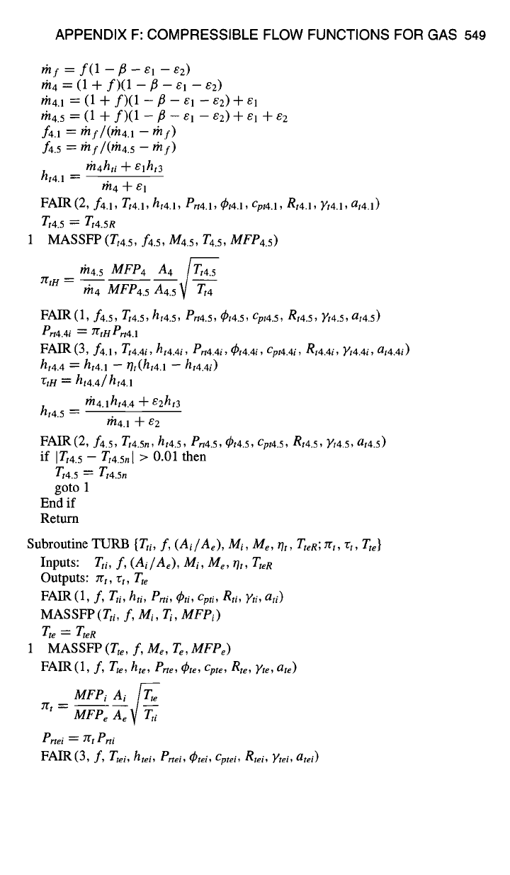
APPENDIX F: COMPRESSIBLE FLOW FUNCTIONS FOR GAS 549
rnf = f(1 -/~
- E1 --
E2)
gt/4
=
(1 + f)(1 -/3 - el -
E2)
?J/4.1 = (1
+ f)(1 -/3
- E l -- '£2) + E1
/'n4. 5 =
(1 + f)(1 -/3 - el - e2) + et + e2
f4.1 ----" thf/(#/4.1 -- rhf)
f4.5 = mf/(rh4.5 - rhf)
th4hti -1- ~ l ht3
ht4.1 --
I'll 4 J¢
E 1
FAIR (2, f4.1,
Tt4.1,
hi4.1,
Prt4.1,
~t4.1,
Cpt4.1,
Rt4.i, Yt4.1,
at4.1)
Tt4.5 ~--- Tt4.5 R
1
MASSFP (Tt4.5, f4.5, M4.5, T4.5,
MFP4.5)
rh4.5
MFP4 A4 T~t4.5
2"ttH = m4 MFP4.5
A4.5"/--V ~
FAIR(I, f4.5, Tt4.5,
ht4.5,
Prt4.5,
~t4.5,
Cpt4.5, gt4.5,
2/t4.5, at4.5)
ert4.4i ---- 7ttH Prt4.1
FAIR
(3, f4.1,
Zt4.4i, ht4.4i, ert4.4i,
~t4.4i,
Cpt4.4i, Rt4.4i, Yt4.4i, at4.4i)
htaA =-- hi4.1 - ot(ht4.1 - ht4.4i)
"Ctn
---- ht4.4/ ht4.1
tha.lht4.4 -1-
E2ht3
ht4.5 =
/~4.1 "~ E2
FAIR
(2, f4.5, Tt4.5,,
ht4.5, Prt4.5,
~bt4.5,
Cpt4.5, Rt4.5,
Yt4.5, at4.5)
if ITt4.5 - Tt4.5.[ > 0.01
then
Tt4.5
=
Tt4.5n
goto
1
End if
Return
Subroutine TURB {Tti,
f, ( Ai / Ae), Mi, Me, Ot, TteR; 7rt, rt, Tte}
Inputs:
Tti, f, ( Ai / Ae), Mi, Me, rh, Ttel~
Outputs: ztt, rt, Tte
FAIR
(1,
f,
Tti, hti, Prti, ~ti, Cpti, gti, Yti, ati)
MASSFP (Tti,
f, Mi, Ti, MFPi)
T,e = TteR
1 MASSFP (Tte, f,
Me, Te, MFPe)
FAIR(I,
f, Tte, hte,
erte, dPte, Cpte, Rte, Yte, ate)
MFPi
ai
.S
7Tt -- MFP----~e Ae V Tti
ertei = 7rt erti
FAIR
(3,
f, Ttei,
htei, Prtei, dPtei, Cptei, Rtei, Ytei, atei)