Mattingly J.D., Heiser W.H., Pratt D.T. Aircraft Engine Design
Подождите немного. Документ загружается.

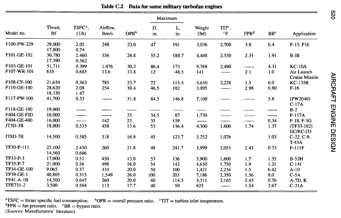
520 AIRCRAFT ENGINE DESIGN
i
,!
rj
o
<
©
[.-,
5
O
~= ~ ~F~ ~
O
~. ~ ~o o~
00~
I'~. '~ "
~ ~ ~ 'T '~ , , ~ ~,.Tm '
.9
H
d
r~
o
II
.O
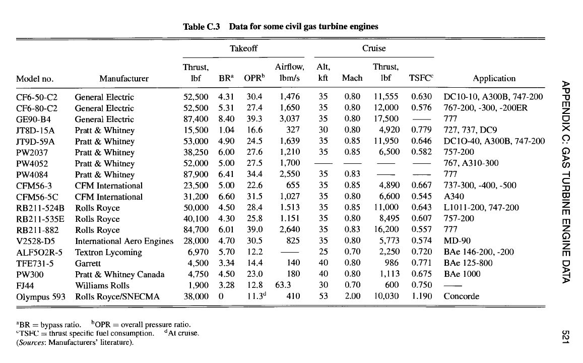
APPENDIX C: GAS TURBINE ENGINE DATA 521
°~
L
~o
i
<
~r
©
i
¢11
d
0
• i-i.i~~. ~ ~i l~z
~~~~ii i
.~
~== " !!iii i~
.~ £
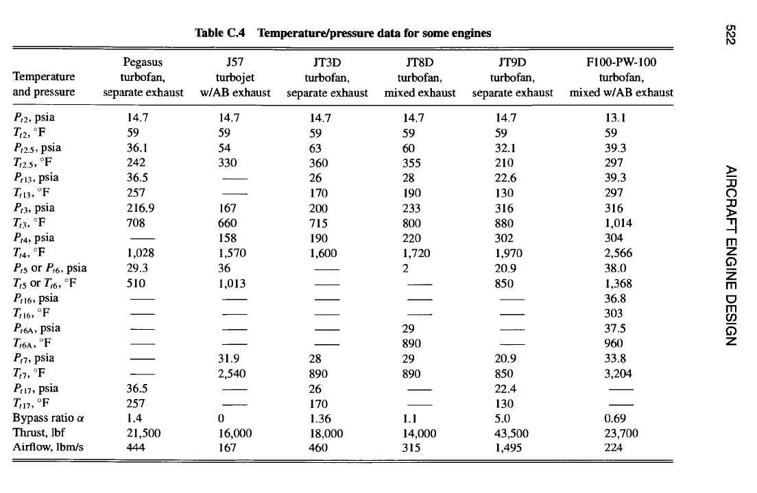
522 AIRCRAFT ENGINE DESIGN
O
O
o
o ~o ~o ~ ~ ~ ~.

Appendix D
Engine Performance:
Theta Break and Throttle Ratio
Aircraft engine designers have recently begun to capitalize on a fundamental
cycle design choice most frequently referred to as either the theta break or throttle
ratio in order to precisely tailor their machines for the expected range of flight
conditions. In the development that follows, you will see that the theta break and
throttle ratio are properties of the engine control system, so that this exploration
takes us beyond the traditional boundaries of aerothermodynamics. This excursion
has the added advantage of demonstrating how aircraft engines behave away from
their reference or design conditions.
Although this development is based largely on a simplified model of the basic
aircraft engine, namely, the single-shaft, uncooled turbojet, experience shows that
the results apply equally well to all families of turbine engines. A special benefit
of this development is the derivation of straightforward, transparent, algebraic
equations that allow the basic workings of turbine engines to be understood
and regulated. This presentation is based on material and nomenclature found in
Chapters 4 and 5 of this textbook and draws heavily upon the foundational material
found in Refs. 1 and 2.
Dimensionless Freestream Total Temperature
Because the freestream total temperature Tt0 will be seen to exert a strong
influence on the internal and overall behavior of the turbojet engine, it is useful to
define a practical, dimensionless form. The dimensionless ratio of the freestream
total temperature to the sea level static temperature of the standard atmosphere is
called theta 0 and given the symbol 00. It is equal to the corrected freestream total
temperature [cf. Eq. (5.22)] and is written as [cf. Eq. (1.1)or (4.5a-CPG)]
Tto
T0(l+ Yc - 1M°2)2
0 0 ~" -- = 0"C r
(D.1)
Tsta Tstd
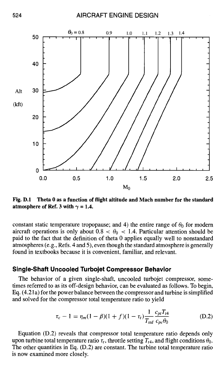
Figure D. 1 displays contours of constant 0o for the standard atmosphere of Ref. 3
and a wide range of flight conditions. The most important message of Fig. D. 1 is
that 00 can be used as a surrogate to condense various combinations of altitude and
Mach number into a single parameter. That is, every point in the flight envelope
possesses a specific value of 00, although the converse is not true. We will therefore
refer hereinafter only to 0o rather than the associated flight conditions.
To increase your fluency with theta 0, it may be helpful to consider that for the
standard atmosphere 1) 00 = 1 at sea level static conditions; 2) 00 can be greater
or less than 1; 3) 00 depends only on Mach number above 37 kft, the start of the
523
524 AIRCRAFT ENGINE DESIGN
Alt
(lift)
00 = 0.8 0.9 1.0 1.1 1.2 1.3 1.4
50
40 1
/ /
30 / 1 t
/ //
20
/
f
/
/ /
lo
/
ii
o /
/, .... , ....
0.0 0.5 1.0 1.5 2.0 2.5
Mo
Fig. D.1 Theta 0 as a function of flight altitude and Mach number for the standard
atmosphere of Ref. 3 with -y = 1.4.
constant static temperature tropopause; and 4) the entire range of 00 for modem
aircraft operations is only about 0.8 < 00 < 1.4. Particular attention should be
paid to the fact that the definition of theta 0 applies equally well to nonstandard
atmospheres (e.g., Refs. 4 and 5), even though the standard atmosphere is generally
found in textbooks because it is convenient, familiar, and relevant.
Single-Shaft Uncooled Turbojet Compressor Behavior
The behavior of a given single-shaft, uncooled turbojet compressor, some-
times referred to as its off-design behavior, can be evaluated as follows. To begin,
Eq. (4.21 a) for the power balance between the compressor and turbine is simplified
and solved for the compressor total temperature ratio to yield
1 cptTt4
(D.2)
"r c -- 1 = r/m(l -- fl)(l + f)(1 --
rt)Tstd
CpcO0
Equation (D.2) reveals that compressor total temperature ratio depends only
upon turbine total temperature ratio rt, throttle setting
Tt4,
and flight conditions 00.
The other quantities in Eq. (D.2) are constant. The turbine total temperature ratio
is now examined more closely.
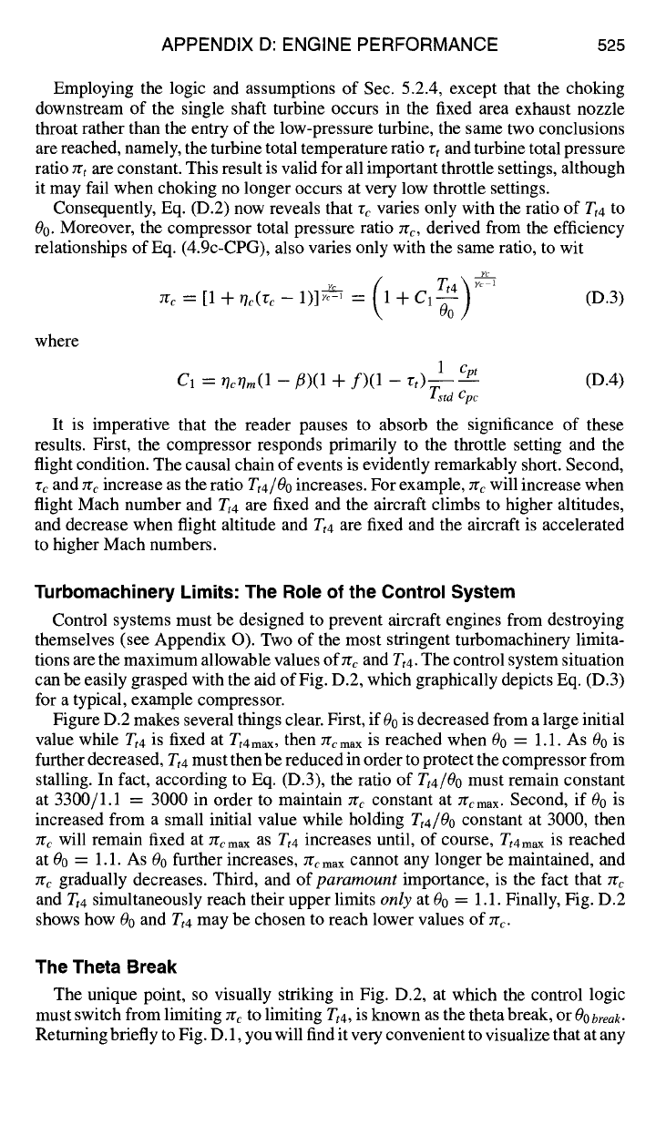
APPENDIX D: ENGINE PERFORMANCE 525
Employing the logic and assumptions of Sec. 5.2.4, except that the choking
downstream of the single shaft turbine occurs in the fixed area exhaust nozzle
throat rather than the entry of the low-pressure turbine, the same two conclusions
are reached, namely, the turbine total temperature ratio rt and turbine total pressure
ratio zrt are constant. This result is valid for all important throttle settings, although
it may fail when choking no longer occurs at very low throttle settings.
Consequently, Eq. (D.2) now reveals that re varies only with the ratio of Tta to
00. Moreover, the compressor total pressure ratio zr~, derived from the efficiency
relationships of Eq. (4.9c-CPG), also varies only with the same ratio, to wit
yc I I ~
Tt4 ~ ~
r~ = [1 + r/c(v~ - 1)1 ~T-~ = ~ 1 + C'l-z--I (D.3)
Uo/
where
1 Cpt
(D.4)
C1 = OcOm(1 -fl)(1
+ f)(1 -
rt) Tstd Cp c
It is imperative that the reader pauses to absorb the significance of these
results. First, the compressor responds primarily to the throttle setting and the
flight condition. The causal chain of events is evidently remarkably short. Second,
r~ and Zrc increase as the ratio
Tt4/O0
increases. For example, Zrc will increase when
flight Mach number and Tt4 are fixed and the aircraft climbs to higher altitudes,
and decrease when flight altitude and
Tt4
are fixed and the aircraft is accelerated
to higher Math numbers.
Turbomachinery Limits: The Role of the Control System
Control systems must be designed to prevent aircraft engines from destroying
themselves (see Appendix O). Two of the most stringent turbomachinery limita-
tions are the maximum allowable values ofrrc and Tt4. The control system situation
can be easily grasped with the aid of Fig. D.2, which graphically depicts Eq. (D.3)
for a typical, example compressor.
Figure D.2 makes several things clear. First, if00 is decreased from a large initial
value while
Tt4
is fixed at
Tt4max,
then
7rcmax
is reached when 00 = 1.1. As 00 is
further decreased,
Tt4
must then be reduced in order to protect the compressor from
stalling. In fact, according to Eq. (D.3), the ratio of
Tt4/Oo
must remain constant
at 3300/1.1 = 3000 in order to maintain zr¢ constant at ~cmax. Second, if 00 is
increased from a small initial value while holding
Tt4/Oo
constant at 3000, then
Zrc will remain fixed at Zrcmax
as Tt4
increases until, of course,
Ztnma x
is reached
at 00 = 1.1. As 0o further increases, Zrcmax cannot any longer be maintained, and
rrc gradually decreases. Third, and of
paramount
importance, is the fact that Jrc
and Tt4
simultaneously reach their upper limits
only
at 00 = 1.1. Finally, Fig. D.2
shows how 00 and
Tt4
may be chosen to reach lower values of rrc.
The Theta Break
The unique point, so visually striking in Fig. D.2, at which the control logic
must switch from limiting Zrc to limiting
Tt4,
is known as the theta break, or 00
brea~.
Returning briefly to Fig. D. 1, you will find it very convenient to visualize that at any
526 AIRCRAFT ENGINE DESIGN
~c
22
20
18
16
14
12
,,l, I I .... I''''1''
~c max
Theta
Break
rt4 max
,,~1
I
I I
10 i i i i i i i i i , i i i i i i
0.8 0.9 1.0 1.1 1.2 1.3
0o
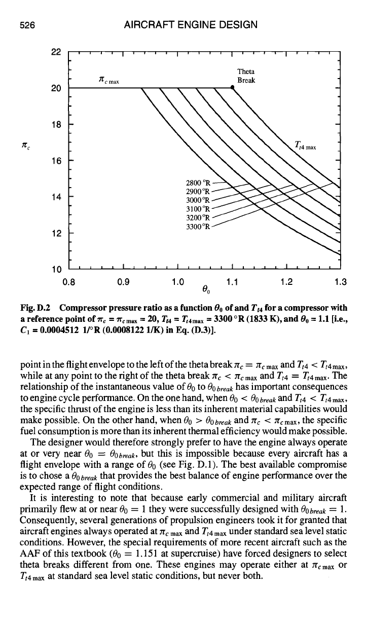
Fig. D.2 Compressor pressure ratio as a function 00 of and
Tt4
for a compressor with
a reference point of 7% = 7% max = 20, Tt4
= Tt4 max ~"
3300 o R (1833 K), and 00 = 1.1 [i.e.,
C1 = 0.0004512 1/°R (0.0008122 l/K) in Eq. (D.3)].
point in the flight envelope to the left of the theta break :rc = ~rc
max
and
Zt4 < Tt4
max,
while at any point to the right of the theta break ~rc < ~r~ max and
Tt4 = Tt4 max.
The
relationship of the instantaneous value of 00 to 00 break has important consequences
to engine cycle performance. On the one hand, when 00 <
Oobreak and
Tt4 < Ttamax,
the specific thrust of the engine is less than its inherent material capabilities would
make possible. On the other hand, when 0o
>
OObreak
and nc < ~cmax, the specific
fuel consumption is more than its inherent thermal efficiency would make possible.
The designer would therefore strongly prefer to have the engine always operate
at or very near 00 =
Oobreak,
but this is impossible because every aircraft has a
flight envelope with a range of 00 (see Fig. D. 1). The best available compromise
is to chose
a
OObreak
that provides the best balance of engine performance over the
expected range of flight conditions.
It is interesting to note that because early commercial and military aircraft
primarily flew at or near 00 = 1 they were successfully designed with
OObreak =
1.
Consequently, several generations of propulsion engineers took it for granted that
aircraft engines always operated at Jr~ max and
Tt4
max
under standard sea level static
conditions. However, the special requirements of more recent aircraft such as the
AAF of this textbook (00 = 1.151 at supercruise) have forced designers to select
theta breaks different from one. These engines may operate either at Jr~max or
Tt4max
at standard sea level static conditions, but never both.

APPENDIX D: ENGINE PERFORMANCE 527
The Throttle Ratio
We now determine how the designer can set the theta break for the engine.
Assuming for the moment that
OObreak
> 1, which is the usual case, and returning
to our earlier conclusion regarding the constancy of the ratio
Tt4/Oo,
it follows
immediately that, for the standard atmosphere
Ttamax Tt4
--
-- --
Tt4SLS
(D.5)
OObreak O0
because
OOSLS
= 1, and that the throttle ratio, or
TR,
is therefore given by
Tt4 max
TR -- -- -- OObreak
(D.6)
Tt4 SLS
The result is surprisingly simple. The engine must merely be designed to have
the
Tt4s~
given by Eq. (D.5) at standard sea level static conditions and must have
a control system that limits zrc to 7rc max and
Zt4
to Ttnma x.
Everything else follows
directly. The terms throttle ratio and theta break are used interchangeably in the
propulsion industry. This should present no problems because, as Eq. (D.6) shows,
they are identical.
It is interesting and useful to determine the sea level flight Mach number at which
the theta break is reached. Returning to Eq. (D.1) and recognizing that 0 = 1 at
standard sea level conditions, it follows immediately that
/
2
MObreak ]------"~(OObreak-
1) (D.7)
=VYc- 1
Equation (D.7) offers the option of selecting a design or reference point at
M0break and standard sea level static conditions with zr~ = ~cmax and
rt4
= rt4raax.
For example, if it is desired to have
00break ~-
1.1, then Eq. (D.7) shows that
MObreak
= 0.707.
It is satisfying to find that the results of AEDsys performance calculations always
precisely and simultaneously obey both Eqs. (D.6) and (D.7).
In the rare case that 00 < 1, a different concept is needed because Tt4 sLs =
Tt4
max
and ~ < rrcmax. One approach would be to use Eq. (D.3) to determine the value
of ~ that exists at standard sea level static conditions. Figure D.1 shows that there
is no relevant
MObre~k
for this case. Another approach would be to specify the
standard day altitude (h) for M0 = 0, as obtained from Eq. (D.1), as the altitude at
which
0 =OObreak
(D.8)
We could, of course, refer to this as the
hbreak.
The Compressor or Engine Operating Line
Another pleasant discovery is that it is now possible to define and construct the
required compressor or engine operating line with little further ado (cf. Secs. 5.3.2
and 7.4.3). It is often surprising, but nevertheless true, that this critical component
characteristic can be determined from first principles. Applying conservation of
528 AIRCRAFT ENGINE DESIGN
mass to the compressor and turbine, and using the mass flow parameter of Sec. 1.9.3
and the corrected flow quantity definitions of Sec. 5.3.1, we find that
7rc zrbPstdA4MFP(M4) O0
= C2Y( c
(D.9)
rhc2 = (1 -/5)(1 + f)
where M4 and MFP(M4) are constant because the turbine entry is presumed to be
choked, and
~b PstdA4MFP(M4)
C2 = (D. 10)
(1 - fl)(1 + f)
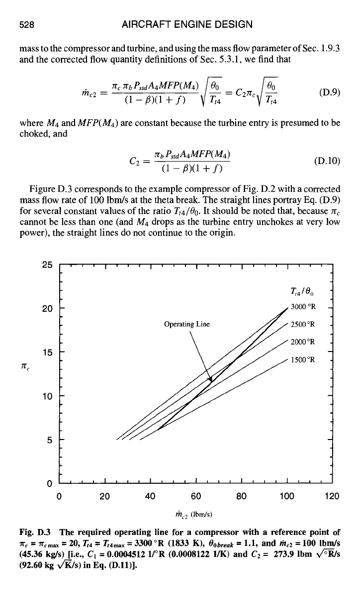
Figure D.3 corresponds to the example compressor of Fig. D.2 with a corrected
mass flow rate of 100 lbm/s at the theta break. The straight lines portray Eq. (D.9)
for several constant values of the ratio Tt4/Oo. It should be noted that, because :re
cannot be less than one (and M4 drops as the turbine entry unchokes at very low
power), the straight lines do not continue to the origin.
25
20
15
ffc
10
'''I'''I'''I' 'I' '
Operating Line
I
T,4 / 0o
3000 °R
2500 °R
2000 °R
1500 °R
0 20 40 60 80 100 120
mc2 (Ibm/s)
Fig. D.3 The required operating line for a compressor with a reference point of
71" c = 71"cmax = 20, rt4 -- Tt4ma x =
3300°R (1833 K),
OObreak --
1.1, and the2 = 100 lbm/s
(45.36 kg/s) [i.e., Ct = 0.0004512 1/°R (0.0008122 l/K) and C2 = 273.9 Ibm x/T--R/s
(92.60 kg v/-K/s) in Eq. (D.11)].
APPENDIX D: ENGINE PERFORMANCE 529
Equation (D.9) may now be combined with Eq. (D.3) to yield the required
compressor operating line, which also appears on Fig. D.3:
rhc2 = Cazrc
(D.11)
zr (J c- l~-/-r" - 1
Because the operating line connects the dots on a series of rays radiating from
the origin, it always has the characteristic shape found in Fig. D.3, which is quite
similar to that of Figs. 5.5 and 7.El 1.
The nature of the predicted and observed compressor operating line is obvi-
ously dictated by the choking of the fixed A4 turbine inlet guide vane. We are
therefore frequently asked at this point whether superior turbine engines could be
designed if the choking assumption were revised. Indeed, a great deal of attention
(Refs. 1 and 6) has been given to experimental turbines having a variable A4 for cy-
cle purposes. This work is stimulating and worth investigating. However, because
the vast preponderance of aircraft engines are deliberately designed to operate with
choked, fixed A4 turbine guide vanes, it is the appropriate model for this textbook.
Uncooled Nonafterburning Single-Shaft Turbojet Performance:
O0
<
O0
break
This line of attack is now carried to a higher level, namely, the evaluation of the
overall performance of the entire engine. You will see that this has many benefits,
including added insight into the behavior of engines and strong analytical support
for the performance correlations of Secs. 2.3.2 and 3.3.2. The inspiration for this
work is Sec. 7.3 of Ref. 1, and several intermediate steps are given next to guide
the reader. Once again, even though the analysis strictly pertains only to a narrow
class of engines, experience shows that it is broadly applicable. To the best of our
knowledge, this is the first time that the complete algebraic analysis of overall
engine performance
with control limits imposed
has been presented.
In this first case, the engine is operating at maximum thrust with 00
<
OObreak,
so that Tt4/00, rc, rCc, rt, and zrt are constant. Six quite reasonable assumptions
are made that retain the underlying physics and provide adequate accuracy while
greatly simplifying the analysis. They are that f and/3 are negligible compared
with one, that Zrd is constant, that t/m = 1, that the engine is always perfectly
expanded (i.e., P9 = P0), and that in Eq. (4.18)
cptTt4
is negligible compared with
hp R (i.e., the energy density of the fuel greatly exceeds that of the combustion
gases).
Following Ref. 1 closely, the uninstalled specific thrust of the engine is given
by the expression
F--a°( Mo V9 )
tho gc Voo - Mo
(D.12)
where
MOVoo = 1- r rd c rb , r.
(D.13)