Mattingly J.D., Heiser W.H., Pratt D.T. Aircraft Engine Design
Подождите немного. Документ загружается.


530 AIRCRAFT ENGINE DESIGN
so that
where
and
F astd
mo~ gc
--fl{Mo}
(D.14)
fl{M0}
=
C3"gr -- lygdTrcT--YCt7~ n
(D.15)
2rt 1 Cpt Tt4
C3 -- -- (D. 16)
yc - 1 Ts,d Cpc Oo
where it is important to note that, for the case at hand, fl is a function only of the
instantaneous flight Mach number M0 through M0, Zrr, and rr.
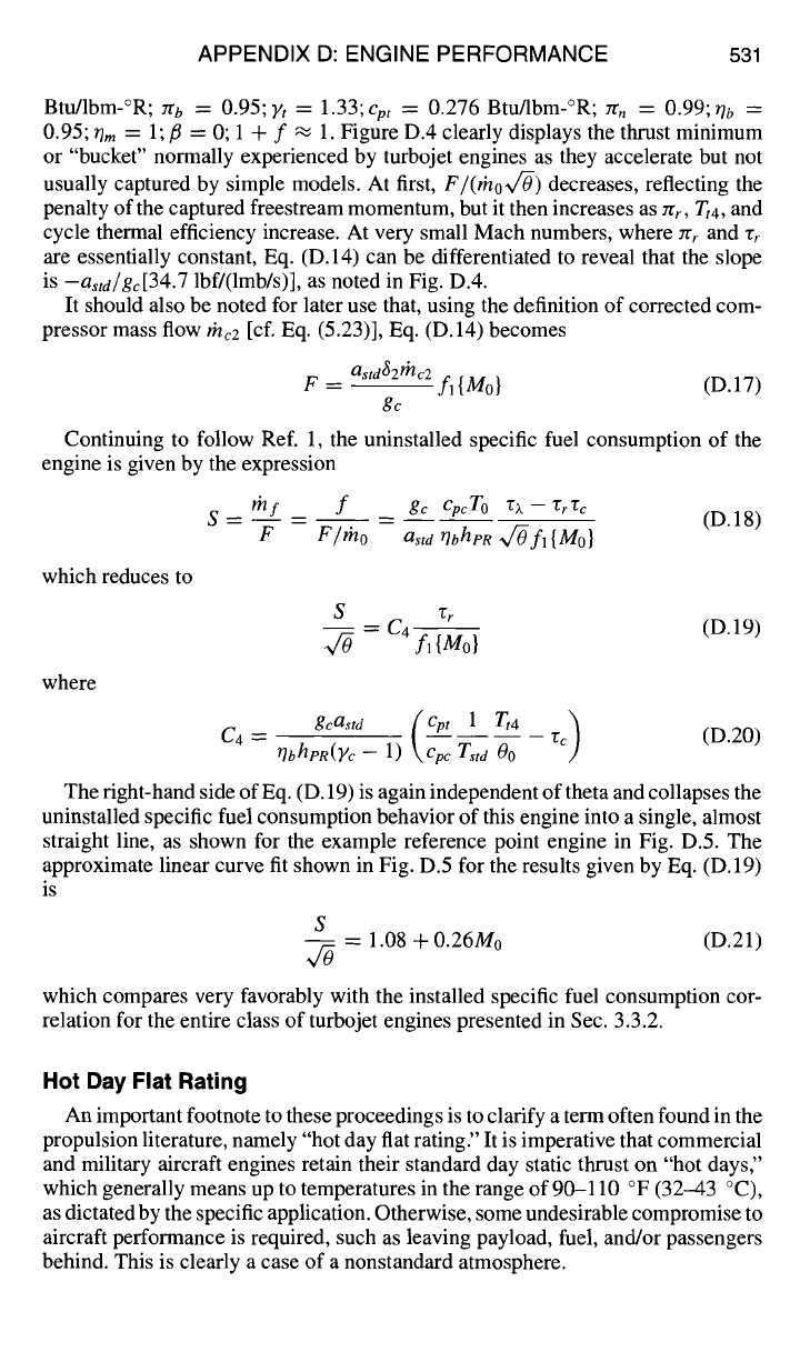
The amazing result of Eqs. (D. 14-D. 16) is that the uninstalled specific thrust be-
havior of this engine collapses into a single line, as shown in Fig. D.4 for the typical
reference point turbojet engine that will be used as the example for the remain-
der of this exposition. Example turbojet engine reference point data are as follows:
Tt4/00 =
3000;ÙObreak = 1.1;hpR = t8,000 Btu/lbm; zrc = 20; r~ = 2.592; Oc =
0.85; r, = 0.7626; ~t
=
0.2957; rh = 0.91; zra = 0.98; Yc = 1.40; c m = 0.238
F
mo40
lbf /
~lbm/s)
115
110
105
100
95
90
0.0
1.0 1.5 2.0
Mo
120
asld
Slope = ---
I I i I
I
I
0.5
Fig. D.4
F/(mox/-O)
vs M0 according to Eqs. (D.14-D.16) for the example reference
point uncooled, single-shaft turbojet engine (C3 = 25.57,
¢cacrcccbcrtcr, =
5.451, and
3't = 1.33).
APPENDIX D: ENGINE PERFORMANCE 531
Btu/lbm-°R; Jro = 0.95; Yt = 1.33;
cpt
= 0.276 Btu/lbm-°R; zrn = 0.99; ~/b =
0.95; /']m = 1;]~ = 0;
1 .ql- f ~ 1. Figure D.4 clearly displays the thrust minimum
or "bucket" normally experienced by turbojet engines as they accelerate but not
usually captured by simple models. At first,
F/(rhov/O)
decreases, reflecting the
penalty of the captured freestream momentum, but it then increases as rcr, Tt4, and
cycle thermal efficiency increase. At very small Mach numbers, where 7/" r and rr
are essentially constant, Eq. (D.14) can be differentiated to reveal that the slope
is
--astd/gc[34.7
lbf/(lmb/s)], as noted in Fig. D.4.
It should also be noted for later use that, using the definition of corrected com-
pressor mass flow rhc2 [cf. Eq. (5.23)], Eq. (D. 14) becomes
astdS2lhc2
F -- -- f~{M0} (D.17)
g~
Continuing to follow Ref. 1, the uninstalled specific fuel consumption of the
engine is given by the expression
S- l~lf _
f _ gc
cpcro ~.- ~r'Cc
(D.18)
F F/rho astd rlbhpR ~v"-Ofi
{M0}
which reduces to
where
S "gr
= C4-- (D.19)
fl{Mo}
gcastd (Cpt 1 Tt4 )
--- rc (D.20)
C4 -- ilbhpR(y c __
1)
\Cpc Tstd O0
The right-hand side of Eq. (D. 19) is again independent of theta and collapses the
uninstalled specific fuel consumption behavior of this engine into a single, almost
straight line, as shown for the example reference point engine in Fig. D.5. The
approximate linear curve fit shown in Fig. D.5 for the results given by Eq. (D. 19)
is
S
-- 1.08 + 0.26M0 (D.21)
which compares very favorably with the installed specific fuel consumption cor-
relation for the entire class of turbojet engines presented in Sec. 3.3.2.
Hot Day Flat Rating
An important footnote to these proceedings is to clarify a term often found in the
propulsion literature, namely "hot day flat rating." It is imperative that commercial
and military aircraft engines retain their standard day static thrust on "hot days,"
which generally means up to temperatures in the range of 90-110 °F (32-43 °C),
as dictated by the specific application. Otherwise, some undesirable compromise to
aircraft performance is required, such as leaving payload, fuel, and/or passengers
behind. This is clearly a case of a nonstandard atmosphere.
532 AIRCRAFT ENGINE DESIGN
s/~
f)
1.7
1.6
1.5
1.4
1.3
1.2
1.1
1.0
0.0
, , , i I ' ' ' ' I ' ' ' ' I ' ' ' ' ~
, , , , I , , , , I , J , , I , , , ,
0.5 1.0 1.5 2.0
M o
Fig. D.5
S/x/-O
vs M0 according to Eqs. (D.19) and (D.21) for the example reference
point uncooled, single-shaft turbojet engine [C4 = 3.012 lbm/Ibf-h (85.31 mg/N-s)].
Since Eq. (D.11) shows that the corrected mass flow is constant when 00 is
less than or equal to
OObre~k,
then Eq. (D.17) reveals that the static thrust is also
constant there. Consequently, setting
OObreak
[cf.
Eq. (D.6)] at or above the ratio
of the absolute hot day flat rating temperature to
Tstd
guarantees that the con-
stant static thrust requirement will be met. This is in every way equivalent to
picking a theta break or throttle ratio for the engine that is greater than one, and
leads to the conclusion that
Tt4
is actually somewhat less than Tt
max
for most en-
gines at standard sea level static conditions. For example, if
Tt4ma x
first occurs at
1.1
Tstd
= 1.1(518.7)°R = 570.6 °R (111.9 °F = 299.2 K = 44.4 °C), then the
O0 break
= 1. l
at M0 = 0.
Uncooled Nonafterburning Single-Shaft Turbojet Performance:
O0
>
O0
break
An entirely analogous and parallel development, with equally appealing results,
is now carried out for the second case of maximum thrust with 0o >
OObreak. The
corresponding situation is that
Tt4 = Ttamax,
Tt, and nt are fixed and the same six
assumptions are made.
Equations (D. 12) and (D. 13) become
F astd
-- --f2{Mo, 0} (D.22)
rho~v/O gc
APPENDIX D: ENGINE PERFORMANCE 533
where
/I ,E 1 }
1 \ v, yc-~
fz{Mo, 0} = --g-
1
.... Mo
7Cd 712b 2"t't 712n f Tr "Jr- C6/0 .]
(D.23)
and
and
and
T;
--
CptTt4max
(D.24)
C pc Tstd
2vt z'~
C5
--
(D.25)
yc-1
C6
~---
~/c(1 - vt)vff (D.26)
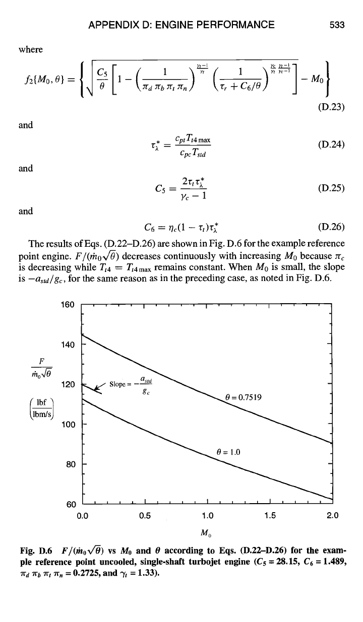
The results of Eqs. (D.22-D.26) are shown in Fig. D.6 for the example reference
point engine.
F/(gno~f-O)
decreases continuously with increasing Mo because ~c
is decreasing while
Tt4
= rt4max
remains constant. When M0 is small, the slope
is
-a,td/g~,
for the same reason as in the preceding case, as noted in Fig. D.6.
160
' ' ' ' I ' ' ' ' I ' ' ' ' I ' ' ' '
F 140
too4-0
120
~lbm/s)
IO0
60 , , ~ ,
I L
, , ~ l , , , , I , , ,
0.0 0.5 1.0 1.5 2.0
Mo
Fig. D.6
F/ffhox/O)
vs M0 and O according to Eqs. (D.22-D.26) for the exam-
ple reference point uncooled, single-shaft turbojet engine (Cs = 28.15, C6 = 1.489,
7rd 7rb ~rt ~r, = 0.2725, and ~'t = 1.33).
534 AIRCRAFT ENGINE DESIGN
Continuing, the uninstalled specific fuel consumption of the engine is given by
the expression
S -- #If __ f __ cpcT 0
(v>,
-- "gt Z'c) (D.27)
F F/mo tib her F/rho
which reduces to
where
= F/(rhoVr#)
(D.28)
cpc T~
C 7 --
(D.29)
rib hpR
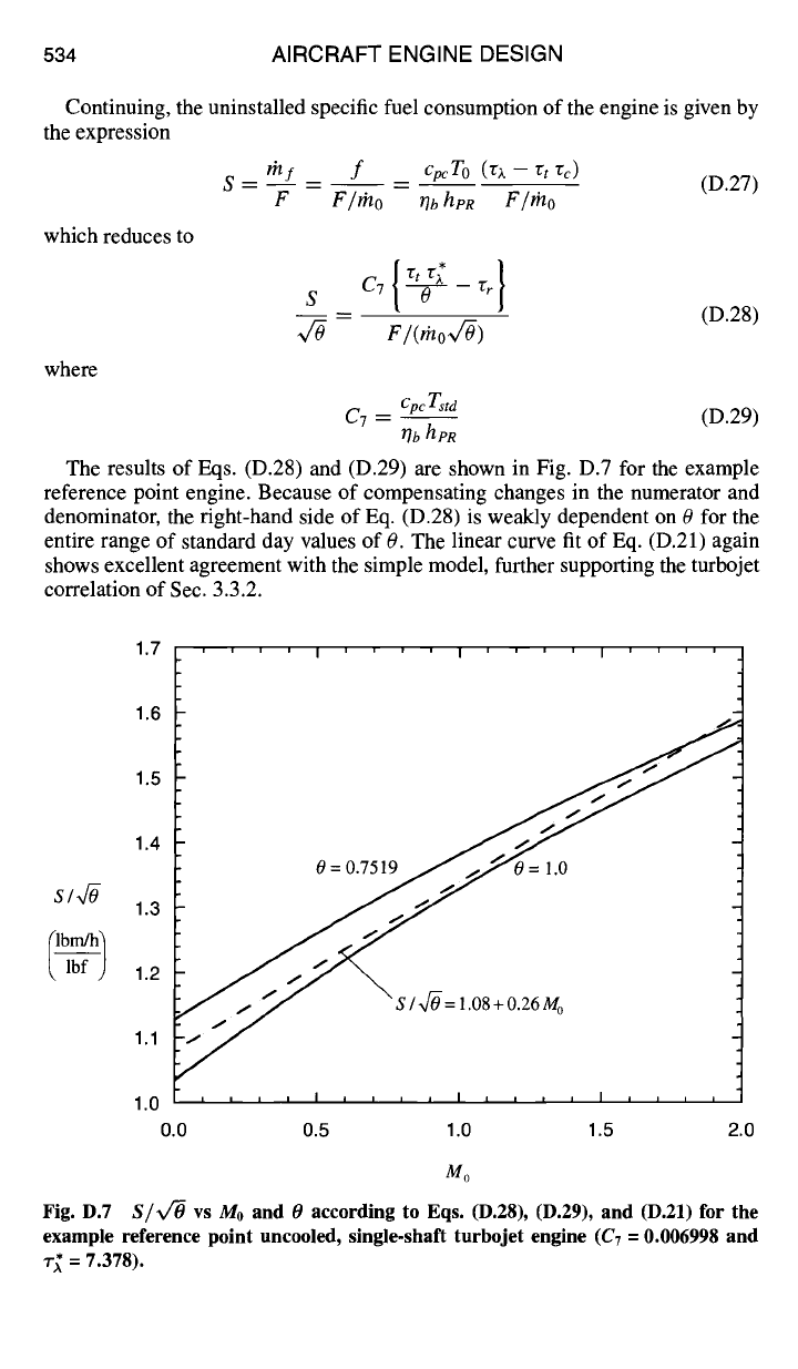
The results of Eqs. (D.28) and (D.29) are shown in Fig. D.7 for the example
reference point engine. Because of compensating changes in the numerator and
denominator, the right-hand side of Eq. (D.28) is weakly dependent on 0 for the
entire range of standard day values of 0. The linear curve fit of Eq. (D.21) again
shows excellent agreement with the simple model, further supporting the turbojet
correlation of Sec. 3.3.2.
1.7
1.6
1.5
1.4
s/~
1.3
1.2
1.1
1.0
0.0
l''''l''''l
o 0 /o
1~ S / x]-O = l .O8 + O.26 Mo
, , , , I , , , , I i i t
l
l I i I I
0.5 1.0 1.5 2,0
m 0
Fig. D.7
S/x/O
vs Mo and 0 according to Eqs. (D.28), (D.29), and (D.21) for the
example reference point uncooled, single-shaft turbojet engine (C7 = 0.006998 and
~-~ = 7.378).
APPENDIX D: ENGINE PERFORMANCE 535
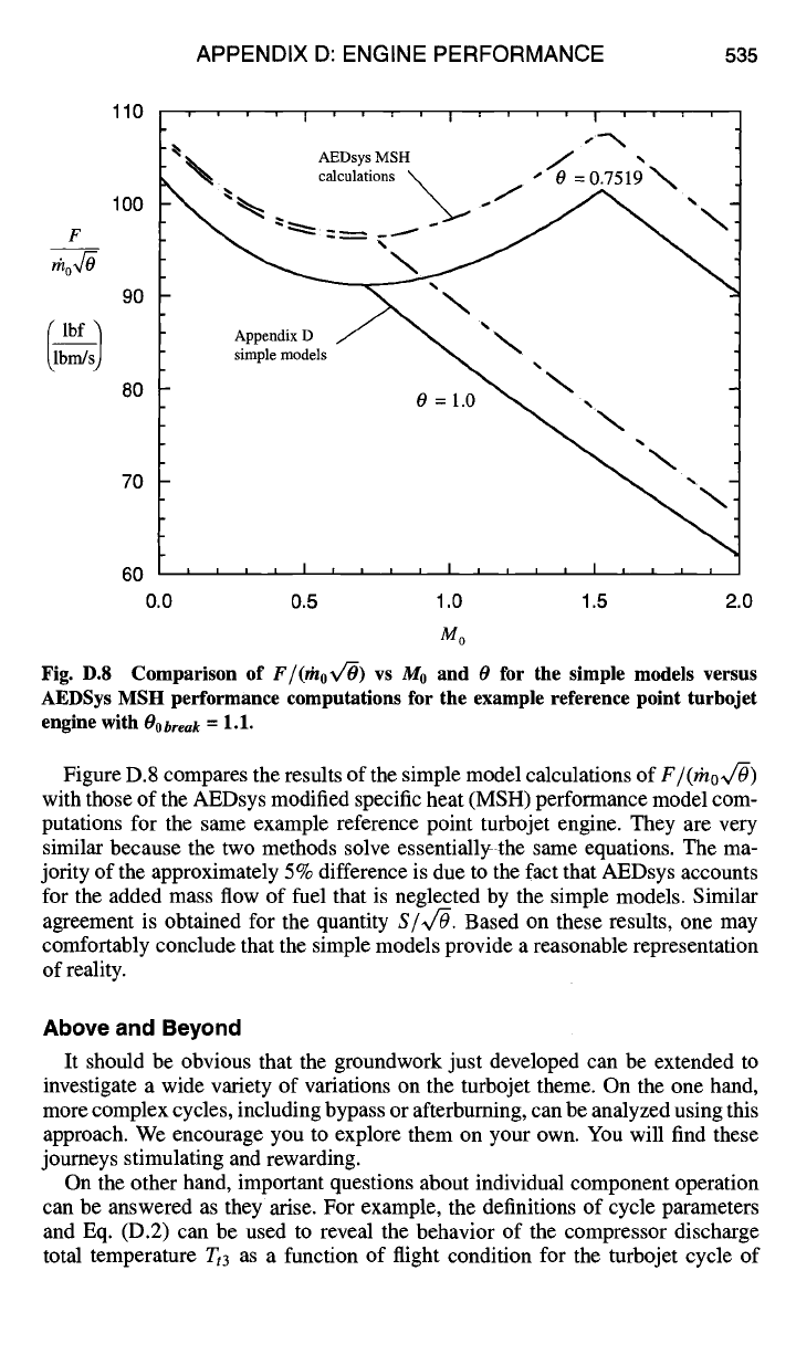
110
i
, i
i I i
, l
i I i i i
,
I
' l i ,
~N~ AEDsys MSH J ,,
-~ calculations \ " 0 = 0.7519
F
100 ~ =-----. r l" ~
¢lUf
~lbm]s) s[mplemod'el s / ~ X
a0 o
=
0.0 0.5
1.0 1.5 2.0
Mo
Fig. D.8 Comparison of
F/(thox/~)
vs M0 and 0 for the simple models versus
AEDSys MSH performance computations for the example reference point turbojet
engine with
OObreak =
1.1.
Figure D.8 compares the results of the simple model calculations of
F/(rho~v/O)
with those of the AEDsys modified specific heat (MSH) performance model com-
putations for the same example reference point turbojet engine. They are very
similar because the two methods solve essentially the same equations. The ma-
jority of the approximately 5% difference is due to the fact that AEDsys accounts
for the added mass flow of fuel that is neglected by the simple models. Similar
agreement is obtained for the quantity
Sfiv/-O.
Based on these results, one may
comfortably conclude that the simple models provide a reasonable representation
of reality.
Above and Beyond
It should be obvious that the groundwork just developed can be extended to
investigate a wide variety of variations on the turbojet theme. On the one hand,
more complex cycles, including bypass or afterburning, can be analyzed using this
approach. We encourage you to explore them on your own. You will find these
journeys stimulating and rewarding.
On the other hand, important questions about individual component operation
can be answered as they arise. For example, the definitions of cycle parameters
and Eq. (D.2) can be used to reveal the behavior of the compressor discharge
total temperature Tt3 as a function of flight condition for the turbojet cycle of
536 AIRCRAFT ENGINE DESIGN
this appendix. This quantity is extremely important from the design standpoint
because it controls the cycle thermal efficiency (see Appendix E) and is limited by
available material capabilities (see Sec. 8.2.3). After some exhilarating algebraic
manipulations, it can be shown that
Tt3/Tstd=03
u~-00Tcmax for00 _< 00bre,k (D.30)
and
Tt3/Tstd = 03 = O0 ~-OObreak(Tc max -- l) for 00 > 00break (D.31)
These remarkably simple expressions reveal that Tt3 is always directly proportional
to 0o, although the slope is less after the theta break than before. The consequences
of this situation are swift and clear. For fighter aircraft that have a large flight
envelope and spend a small fraction of their flight time at their maximum 00, the
compressor discharge temperature is usually less than the maximum allowable
value. For supersonic transport aircraft that cruise at their maximum 00, the com-
pressor discharge temperature is usually at the maximum allowable value. Thus,
the
Tt3
material selection problem can be much more difficult for the transport
aircraft than for the fighter aircraft.
But the fun is not over yet. Equations (D.30) and (D.31) allow the possibility
that T,3
max
will be reached before the design O0break, and the throttle will have to
be retarded. For a typical value of Tt3 max/T~ta of 3.5 and the rcmax = 2.592 and
OObreak
-~-
l. 1 of the example turbojet, Eq. (D.31) shows that 00 must exceed 1.75
(i.e., M0 > 1.94 at 0 = 1) before the compressor discharge materials limitation is
reached. Although there is no conflict for this example case, we have discovered
another boundary that could be placed on Fig. D.1 that must be examined for
every new engine. And once this boundary is reached, another break in all of
the performance parameters will occur. Can you use Eq. (D.31) to determine the
general behavior of r~ and Tt4
once
Tt3
max
is reached?
You will find it worthwhile to repeat this investigation for the compressor dis-
charge pressure, which is also limited by available materials.
And so it goes. We hope that these and the other examples found in this textbook
encourage you to use this framework as thefirst resort when trying to understand
the fundamentals of jet engine operation.
References
J Oates, G. C., The Aerothermodynamics of Gas Turbine and Rocket Propulsion, 3rd ed.,
AIAA Education Series, AIAA, Reston, VA, 1997.
2Mattingly, J. D., Elements of Gas Turbine Propulsion, McGraw-Hill, New York, 1996.
3U. S. Standard Atmosphere, 1976, U.S. Government Printing Office, Washington, DC,
Oct. 1976.
4"Climatic Information to Determine Design and Test Requirements for Military Equip-
ment," U.S. Dept. of Defense, M1L-STD-210C, Rev. C, Jan. 1997.
s,,Climatic Information to Determine Design and Test Requirements for Military Equip-
ment," U.S. Dept. of Defense, M1L-STD-21OA, Nov. 1958.
6Oates, G. C. (ed.), Aerothermodynamics of Aircraft Engine Components, AIAA Educa-
tion Series, AIAA, Reston, VA, 1985, p. 263.
Appendix E
Aircraft Engine Efficiency and Thrust Measures
The goal of this appendix is to provide a deeper appreciation and understanding
of the efficiency and thrust measures that you will encounter in this textbook and in
practice. The title immediately reveals that there is no single, universal measure of
engine efficiency or thrust that serves all purposes. Engineers and designers have
found it necessary instead to define and use many different efficiency and thrust
measures. Three efficiency measures and four of the most frequently cited thrust
measures will be developed here in detail. All flows are assumed to be steady in
the cyclic time average, propulsion sense.
Please note that the definition of each is plain and unambiguous and that, al-
though this material is based on a single exhaust flow engine configuration, it can
easily be extended to multiple exhaust flow situations. The material that follows has
benefited greatly from Refs. 1 and 2 and repeatedly employs the impulse function
as described in Sec. 1.9.5.
Overall Efficiency
The function of the airbreathing engine, viewed as a thermodynamic cycle,
is to convert the chemical energy stored in the fuel into mechanical energy for
the aerospace system. This leads to a performance measure called overall effi-
ciency that, although always introduced but seldom intensely pursued in the litera-
ture, is particularly revealing and is presented in all AEDsys engine computations
(see Secs. 4.2.7 and 4.2.8). The rate at which the engine makes mechanical energy
available to the aerospace system is known as the thrust power and is given by the
expression
Thrust power =
FVo
(E.1)
where it has been assumed that the thrust is parallel to the direction of flight.
Placing an unambiguous value on the rate at which the chemical reactions make
energy available to the engine cycle requires some thought. The standard practice
in the propulsion and power industry is to represent the actual combustion process
by a fictitious one in which the pressure is constant and there are no heat or work
interactions, namely the heat of reaction or heating value of the fuel
heR,
as defined
in Chapter 9. The rate at which the chemical reactions make energy available to
the engine cycle for the overall fuel flow rate of/nj; is therefore
Chemical energy rate = rn f~, h PR (E.2)
537
538 AIRCRAFT ENGINE DESIGN
An alternative approach would be to add the kinetic energy of the fuel being
consumed (i.e.,
Vo2/2)
to the heat of reaction in order to account for the energy
required to make the fuel available to the engine. We have not used this method
for several reasons. First, on philosophical grounds, one has no choice but to
carry the fuel aloft, and the thermodynamic cycle has no way to capitalize on
this kinetic energy because it vanishes in the aircraft/engine frame of reference.
Second, because the kinetic energy is less than about 1% of the heat of reaction
over the normal operating envelope of turbine engines, it would have a negligible
effect on the numerical results.
Based on the foregoing, the overall efficiency 0o of the airbreathing engine
cycle is defined as
Thrust power F V0
= = -- (E.3)
Overall Efficiency ~7o Chemical energy rate
t:nfoheR
It should be emphasized that the overall efficiency is a direct indicator of how
well the engine uses the energy originally deposited in the fuel tanks or, conversely,
how much fuel must be put onboard in order to provide the propulsive energy
needed for a given mission. Moreover, common-sense application of the second law
of thermodynamics leads to the conclusion that overall efficiency cannot exceed 1;
otherwise the chemical energy of the fuel could be restored and the surplus of
mechanical energy used to create perpetual motion.
Thermal Efficiency and Propulsive Efficiency
It can be very enlightening to further break down the airbreathing engine overall
efficiency into its "grass roots" constituents as follows:
Engine mechanical power Thrust power
r/o =
Chemical energy rate Engine mechanical power
Thermal efficiency r/T/4 Propulsive efficiency 0P
This word equation reveals that our purpose is to follow the energy along its
"food chain" from chemical (in the fuel tank) to mechanical (generated by the
engine) to the aerospace system (thrust power). Provided that the exhaust flow is
perfectly expanded to atmospheric pressure and no bleed air or shaft takeoff power,
the mechanical power generated by the engine manifests itself only as a change in
kinetic energy of the flow, so that
1
Engine mechanical power = (rno + rhL)-~ - rho-2~ -
gc
and, therefore, that
r'n° {(l + fo)V92 FoX}
=g-7
gc 2 2 F Vo
0° = r/TH0/' =
fohpR __
m0 {(1 + f°)~ 2
gc
V2} 2 (E.4)
where
fo
=
ITt fo/rrta
was mcorporated.
APPENDIX E: ENGINE EFFICIENCY AND THRUST MEASURES539
Thermodynamic analysis of engine cycles teaches us that thermal efficiency
primarily increases with Tt3/To = rrrc, and therefore with zrc, although Orn can-
not exceed (Ref. 1). This is the driving force behind high-pressure ratio aircraft
engine cycles. Furthermore, because the uninstalled thrust when the exhaust flow
is perfectly matched to atmospheric pressure is merely the change in momentum
flux from entry to exhaust, then
1
F = --{(rh0 -4-
lhfo)V9 --/h0V0}
=
m°{(1 +
fo)V9
--
V0} (E.5)
gc gc
so that the propulsive efficiency portion of Eq. (E.4) becomes
/ }// (v9) }
OP=2 (l+fo)~00-1 (l+fo) ~00 -1 (E.6)
which shows that propulsive efficiency primarily increases as the ratio of the ex-
haust velocity to the freestream velocity decreases. This is the driving force behind
high bypass ratio aircraft engine cycles, which spread the available engine mechan-
ical power across more air in order to reduce this velocity ratio. By noting that
the fuel/air ratio is small compared 1 even for stoichiometric combustion (see Sec.
9.1.2), a reasonable approximation and the most revealing formula for propulsive
efficiency is obtained by using this fact to reduce Eq. (E.6) to
2
~p _ (E.7)
V9 / Vo --[.-1
This is the most transparent and frequently encountered form and, because ex-
haust velocity must exceed inlet velocity in order to obtain positive thrust, this
approximation for propulsive efficiency never exceeds 1.
The exact value of propulsive efficiency given by Eq. (E.6) is always slightly
larger than the approximate value given by Eq. (E.7) as a result of the presence of the
very small additional fuel mass over which the energy is spread. Close examination
of Eq. (E.6) will reveal, for example, that the exact propulsive efficiency will always
be less than 1 even for arbitrarily large fuel air ratios provided that
V9/Vo
is greater
than 2. You are encouraged to calculate both versions of propulsive efficiency and
draw your own conclusions.
Performance Measure Interrelationships
The conventional definitions may be arranged to yield a complete set of exact
interrelationships between the airbreathing engine performance measures. The
results of these manipulations are presented in Table E. 1.
One important and immediate conclusion that can be drawn from these interre-
lationships is that, for a fixed value of r/o, S is directly proportional to V0 while
F/fno
is inversely proportional to V0. Knowledge of these trends is often a shortcut
to useful conclusions.
Airbreathing Engine Performance Measure Example
It is generally true that specifying the flight speed, the fuel heating value, and
any two performance measures allows all of the others to be calculated. The ex-
ample that follows will demonstrate a typical case of this assertion, as well as