Mattingly J.D., Heiser W.H., Pratt D.T. Aircraft Engine Design
Подождите немного. Документ загружается.

DESIGN: INLETS AND EXHAUST NOZZLES
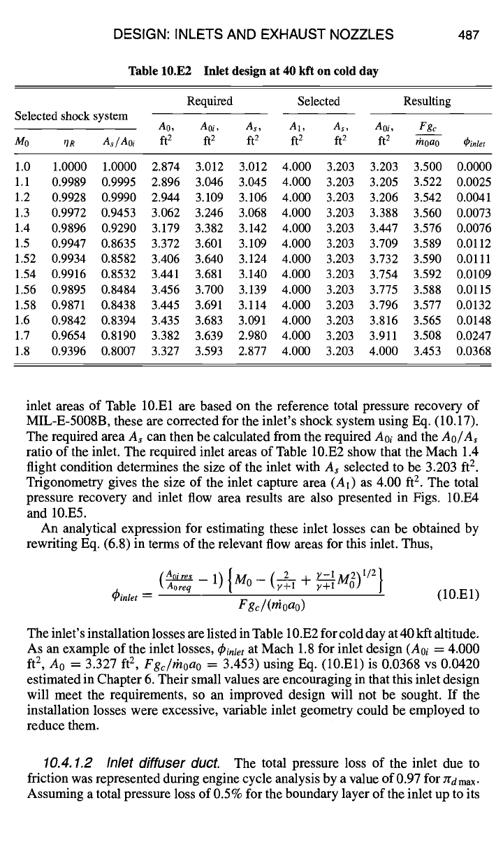
Table 10.E2 Inlet design at 40 kft on cold day
487
Required Selected Resulting
Selected shock system
AO,
Aoi, As, A1, As, Aoi, Fgc
Mo
~R
As/Aoi
ft 2 ft 2 ft 2 ft 2 ft 2 ft 2 Ih0a0
~inlet
1.0 1.0000 1.0000 2.874 3.012 3.012 4.000 3.203 3.203 3.500 0.0000
1.1 0.9989 0.9995 2.896 3.046 3.045 4.000 3.203 3.205 3.522 0.0025
1.2 0.9928 0.9990 2.944 3.109 3.106 4.000 3.203 3.206 3.542 0.0041
1.3 0.9972 0.9453 3.062 3.246 3.068 4.000 3.203 3.388 3.560 0.0073
1.4 0.9896 0.9290 3.179 3.382 3.142 4.000 3.203 3.447 3.576 0.0076
1.5 0.9947 0.8635 3.372 3.601 3.109 4.000 3.203 3.709 3.589 0.0112
1.52 0.9934 0.8582 3.406 3.640 3.124 4.000 3.203 3.732 3.590 0.0111
1.54 0.9916 0.8532 3.441 3.681 3.140 4.000 3.203 3.754 3.592 0.0109
1.56 0.9895 0.8484 3.456 3.700 3.139 4.000 3.203 3.775 3.588 0.0115
1.58 0.9871 0.8438 3.445 3.691 3.114 4.000 3.203 3.796 3.577 0.0132
1.6 0.9842 0.8394 3.435 3.683 3.091 4.000 3.203 3.816 3.565 0.0148
1.7 0.9654 0.8190 3.382 3.639 2.980 4.000 3.203 3.911 3.508 0.0247
1.8 0.9396 0.8007 3.327 3.593 2.877 4.000 3.203 4.000 3.453 0.0368
inlet areas of Table 10.El are based on the reference total pressure recovery of
MIL-E-5008B, these are corrected for the inlet's shock system using Eq. (10.17).
The required area A~ can then be calculated from the required Aoi and the
Ao/A~
ratio of the inlet. The required inlet areas of Table 10.E2 show that the Mach 1.4
flight condition determines the size of the inlet with A~ selected to be 3.203 ft 2.
Trigonometry gives the size of the inlet capture area (A1) as 4.00 ft 2. The total
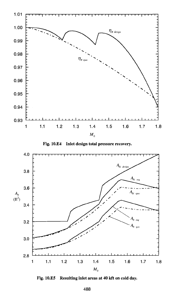
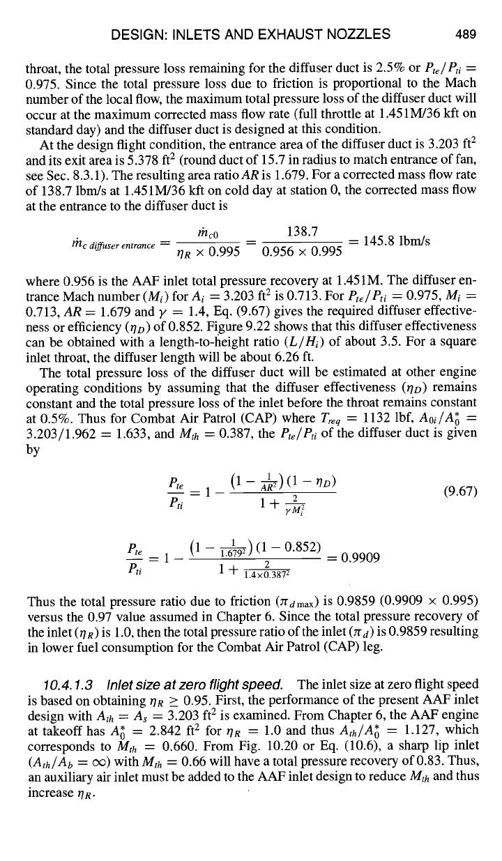
pressure recovery and inlet flow area results are also presented in Figs. 10.E4
and 10.E5.
An analytical expression for estimating these inlet losses can be obtained by
rewriting Eq. (6.8) in terms of the relevant flow areas for this inlet. Thus,
(Ao/re~ _ 1) {Mo _ (7~y - t-
Y-1M2~l/2~
Aoreq ~ O] J
~inlet =
(10.El)
Fgc/(nioao)
The inlet's installation losses are listed in Table 10.E2 for cold day at 40 kft altitude.
As an example of the inlet losses,
(/)inlet
at Mach 1.8 for inlet design (Aoi
=
4.000
ft 2, A0 = 3.327 ft 2,
Fgc/rhoao
= 3.453) using Eq. (10.El) is 0.0368 vs 0.0420
estimated in Chapter 6. Their small values are encouraging in that this inlet design
will meet the requirements, so an improved design will not be sought. If the
installation losses were excessive, variable inlet geometry could be employed to
reduce them.
10.4.1.2 Inlet diffuser duct.
The total pressure loss of the inlet due to
friction was represented during engine cycle analysis by a value of 0.97 for ]rd max.
Assuming a total pressure loss of 0.5% for the boundary layer of the inlet up to its
1.01
1.00
0.99
0.98
0.97
0.96
0.95
0.94
0.93
4.0
3.8
3.6
Ao
(ft 2)
3.4
3.2
3.0
2.8
''''I''''I''''I''''I''''I''''I''''I''''
~ec "" • ,,,, \, .,,,,,,,, ,,
, , , , I , , , , I , , , , I , , , , I , , , , I , , , , I , , , , I , , , ,
1.1 1.2 1.3 1.4 1.5 1.6 1.7 1.8
Mo
Fig. 10.E4 Inlet design total pressure recovery.
.... , .... , .... , .... , .... ,,-,::,,~,,,,,,:7
/° -
/-/°/
1.1 1.2 1.3 1.4 1.5 1.6 1.7 1.8
Mo
Fig. 10.E5 Resulting inlet areas at 40 kft on cold day.
488
DESIGN: INLETS AND EXHAUST NOZZLES 489
throat, the total pressure loss remaining for the diffuser duct is 2.5% or
P~e/P~i =
0.975. Since the total pressure loss due to friction is proportional to the Mach
number of the local flow, the maximum total pressure loss of the diffuser duct will
occur at the maximum corrected mass flow rate (full throttle at 1.451M/36 kft on
standard day) and the diffuser duct is designed at this condition.
At the design flight condition, the entrance area of the diffuser duct is 3.203 ft 2
and its exit area is 5.378 ft 2 (round duct of 15.7 in radius to match entrance of fan,
see Sec. 8.3.1). The resulting area ratio
AR
is 1.679. For a corrected mass flow rate
of 138.7 lbm/s at 1.451M/36 kft on cold day at station 0, the corrected mass flow
at the entrance to the diffuser duct is
mc
diffuser entrance --
rhc0 138.7
~R x 0.995 0.956 x 0.995
-- 145.8 lbm/s
where 0.956 is the AAF inlet total pressure recovery at 1.451M. The diffuser en-
trance Mach number
(Mi)
for
Ai
= 3.203
ft 2
is 0.713. For
Pte/Pti
= 0.975,
Mi =
0.713,
AR
= 1.679 and y = 1.4, Eq. (9.67) gives the required diffuser effective-
ness or efficiency 0/D) of 0.852. Figure 9.22 shows that this diffuser effectiveness
can be obtained with a length-to-height ratio
(L/Hi)
of about 3.5. For a square
inlet throat, the diffuser length will be about 6.26 ft.
The total pressure loss of the diffuser duct will be estimated at other engine
operating conditions by assuming that the diffuser effectiveness (0D) remains
constant and the total pressure loss of the inlet before the throat remains constant
at 0.5%. Thus for Combat Air Patrol (CAP) where
Treq
= 1132 lbf,
Aoi/A~ =
3.203/1.962 = 1.633, and
Mth
= 0.387, the
Pte/Pti
of the diffuser duct is given
by
--= (1 - ~) (1 - ~/D)
Pte
1 - (9.67)
P,i 1 + y~2
1-- 1
P e = 1 - ~) (1 - 0.852)
2
Pti
1 --1- 1.4x0.3872
= 0.9909
Thus the total pressure ratio due to friction (rramax) is 0.9859 (0.9909 × 0.995)
versus the 0.97 value assumed in Chapter 6. Since the total pressure recovery of
the inlet (OR) is 1.0, then the total pressure ratio of the inlet (red) is 0.9859 resulting
in lower fuel consumption for the Combat Air Patrol (CAP) leg.
10.4.1.3 Inlet size at zero flight speed.
The inlet size at zero flight speed
is based on obtaining ~TR >_ 0.95. First, the performance of the present AAF inlet
design with
Ath = As
= 3.203
ft 2
is examined. From Chapter 6, the AAF engine
at takeoff has A~ = 2.842
ft 2
for OR = 1.0 and thus
Ath/A~
= 1.127, which
corresponds to
Mth
= 0.660. From Fig. 10.20 or Eq. (10.6), a sharp lip inlet
(Ath/Ab
= oo) with
Mth
= 0.66 will have a total pressure recovery of 0.83. Thus,
an auxiliary air inlet must be added to the AAF inlet design to reduce
Mth
and thus
increase ~/R.
490 AIRCRAFT ENGINE DESIGN
Designing for OR = 0.95, Eq. (10.6) gives Mth = 0.285. The required one-
dimensional inlet throat area
(Ath)
is determined using
rhcV'~,d
Ath
= (10.E2)
PstdMFP( Mth )
Thus
132.34~/518.7
Ath
= = 5.709 ft 2
2116 x 0.2495
and an auxiliary air inlet whose throat area is 2.506 ft 2 (5.709 - 3.203) needs
to be added to the AAF inlet design to meet the total pressure recovery goal
of 0.95.
The AAF inlet with auxiliary air inlet door now has a total pressure recovery of
0.95 and
~inlet
of 0.0578 (assuming A1 =
Ath)
as compared to the Chapter 6 values
of 0R = 1.0 and
dPinlet
= 0.0929. The total pressure ratio of the diffuser duct with
AR
~ 1 (5.378/5.709) is one. Thus,
7~dmax
is 0.995 and Zrd = (0.95)(0.995) =
0.9452.
10.4.1.4 Inlet performance during takeoff.
Flow separation from the in-
side surface of the sharp lips of the inlet must be reduced during subsonic flight.
An auxiliary air inlet was added to the AAF inlet to reduce the external flow sepa-
ration at zero flight speed. This same auxiliary air inlet can be used to reduce flow
separation at other subsonic flight conditions that have low total pressure recovery
(0R) with accompanying high inlet throat Mach number. The area ratio
Ao/Ath
can
be used to identify those flight conditions at which lip flow separation may be a
problem (see Fig. 10.58). Only Segments A, B, and C of Mission Phase 1-2 have
A0 larger than 4.0
ft 2
and Segments B and C have not yet been analyzed.
It is assumed that the auxiliary air inlet sized for zero flight speed is also used for
Segments B and C, also giving them a total inlet throat area of 5.709 ft e. Off-design
engine cycle analyses give the required reference
Aowec
for Segments B and C of
16.55
ft 2
and 9.154 ft 2, respectively. The resulting
Ao/Ath,
Mth, and ~/n (estimated
from Fig. 10.58) are tabulated:
Segment
Mo Ao/ Ath
Mth
OR
B 0.10 2.899 0.205 0.98
C 0.18 1.603 0.396 0.97
Based on a constant total pressure effectiveness (0D) of the diffuser duct and
Eq. (9.67), the inlet total pressure ratio (Zrd) for Segments B and C are 0.97 and
0.98, respectively, as compared to the value of 0.97 used for both in the engine
cycle analysis.
10.4.1.5 AAF inlet performance.
The performance of the AAF inlet de-
sign can now be calculated at all flight conditions and compared to the estimates
DESIGN: INLETS AND EXHAUST NOZZLES
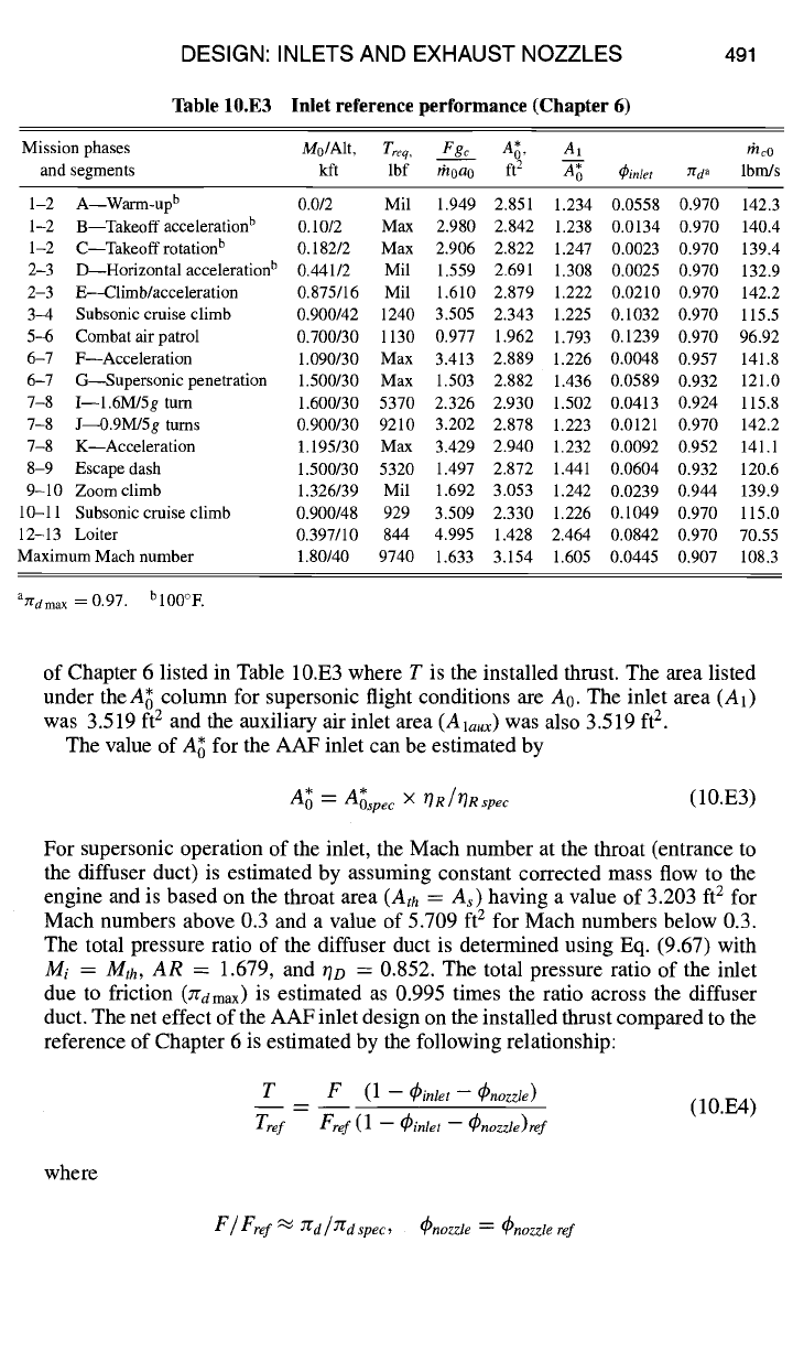
Table 10,E3 Inlet reference performance (Chapter 6)
491
Mission phases
Mo/Alt,
Treq,
Fgc A~,
AI rhcO
and segments
kft lbf
&oao
ft 2
A-~o
¢inlet
Yrda
lbm/s
1-2 A--Warm-up b 0.0/2 Mil 1.949 2.851 1.234 0.0558 0.970 142.3
1-2 B--Takeoff acceleration b 0.10/2 Max 2.980 2.842 1.238 0.0134 0.970 140.4
1-2 C--Takeoffrotation b 0.182/2 Max 2.906 2.822 1.247 0.0023 0.970 139.4
2-3 D--Horizontal acceleration b 0.441/2 Mil 1.559 2.691 1.308 0.0025 0.970 132.9
2-3
E--Climb~acceleration
0.875/16 Mil 1.610 2.879 1.222 0.0210 0.970 142.2
3-4
Subsonic cruise climb
0.900/42 1240 3.505 2.343 1.225 0.1032 0.970 115.5
5-45
Combat air patrol
0.700/30 1130 0.977 1.962 1.793 0.1239 0.970 96.92
6-7 F--Acceleration 1.090/30 Max 3.413 2.889 1.226 0.0048 0.957 141.8
6-7
G--Supersonic penetration
1.500/30 Max 1.503 2.882 1.436 0.0589 0.932 121.0
7-8 I--1.6M/5g turn 1.600/30 5370 2.326 2.930 1.502 0.0413 0.924 115.8
7-8 J~0.9M/5g
turns
0.900/30 9210 3.202 2.878 1.223 0.0121 0.970 142.2
7-8 K--Acceleration 1.195/30 Max 3.429 2.940 1.232 0.0092 0.952 141.1
8-9
Escape dash
1.500/30 5320 1.497 2.872 1.441 0.0604 0.932 120.6
9-10 Zoomclimb 1.326/39 Mil 1.692 3.053 1.242 0.0239 0.944 139.9
10-11
Subsonic cruise climb
0.900/48 929 3.509 2.330 1.226 0.1049 0.970 115.0
12-13 Loiter 0.397/10 844 4.995 1.428 2.464 0.0842 0.970 70.55
MaximumMach number
1.80/40 9740 1.633 3.154 1.605 0.0445 0.907 108.3
aT~dmax = 0.97.
bl00°F.
of Chapter 6 listed in Table 10.E3 where T is the installed thrust. The area listed
under theA~ column for supersonic flight conditions are A0. The inlet area (At)
was 3.519 ft 2 and the auxiliary air inlet area (Ala~,) was also 3.519 ft 2.
The value of A; for the AAF inlet can be estimated by
A~ = *
Aospec
× OR/ORspec
(10.E3)
For supersonic operation of the inlet, the Mach number at the throat (entrance to
the diffuser duct) is estimated by assuming constant corrected mass flow to the
engine and is based on the throat area
(Ath = As)
having a value of 3.203 ft 2 for
Mach numbers above 0.3 and a value of 5.709 ft 2 for Mach numbers below 0.3.
The total pressure ratio of the diffuser duct is determined using Eq. (9.67) with
Mi = Mth, AR
= 1.679, and 0o = 0.852. The total pressure ratio of the inlet
due to friction (:rdm~x) is estimated as 0.995 times the ratio across the diffuser
duct. The net effect of the AAF inlet design on the installed thrust compared to the
reference of Chapter 6 is estimated by the following relationship:
T F
(1 --
(~inlet -- (Pnozzle)
(10.E4)
Tre f Ere f
(1
-
(/)inlet -- (~nozzle)ref
where
F / Fref ~ Zr d / Zr d ~pec ,
~.ozzl~
= Cnozzte ref
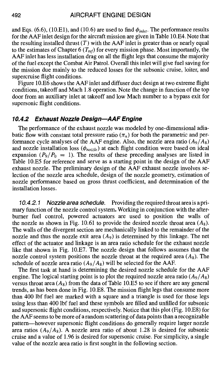
492 AIRCRAFT ENGINE DESIGN
and Eqs. (6.6), (10.El), and (10.6) are used to find
~inlet.
The performance results
for the AAF inlet design for the aircraft mission are given in Table 10.E4. Note that
the resulting installed thrust (T) with the AAF inlet is greater than or nearly equal
to the estimates of Chapter 6
(Trey)
for every mission phase. Most importantly, the
AAF inlet has less installation drag on all the flight legs that consume the majority
of the fuel except the Combat Air Patrol. Overall this inlet will give fuel saving for
the mission due mainly to the reduced losses for the subsonic cruise, loiter, and
supercruise flight conditions.
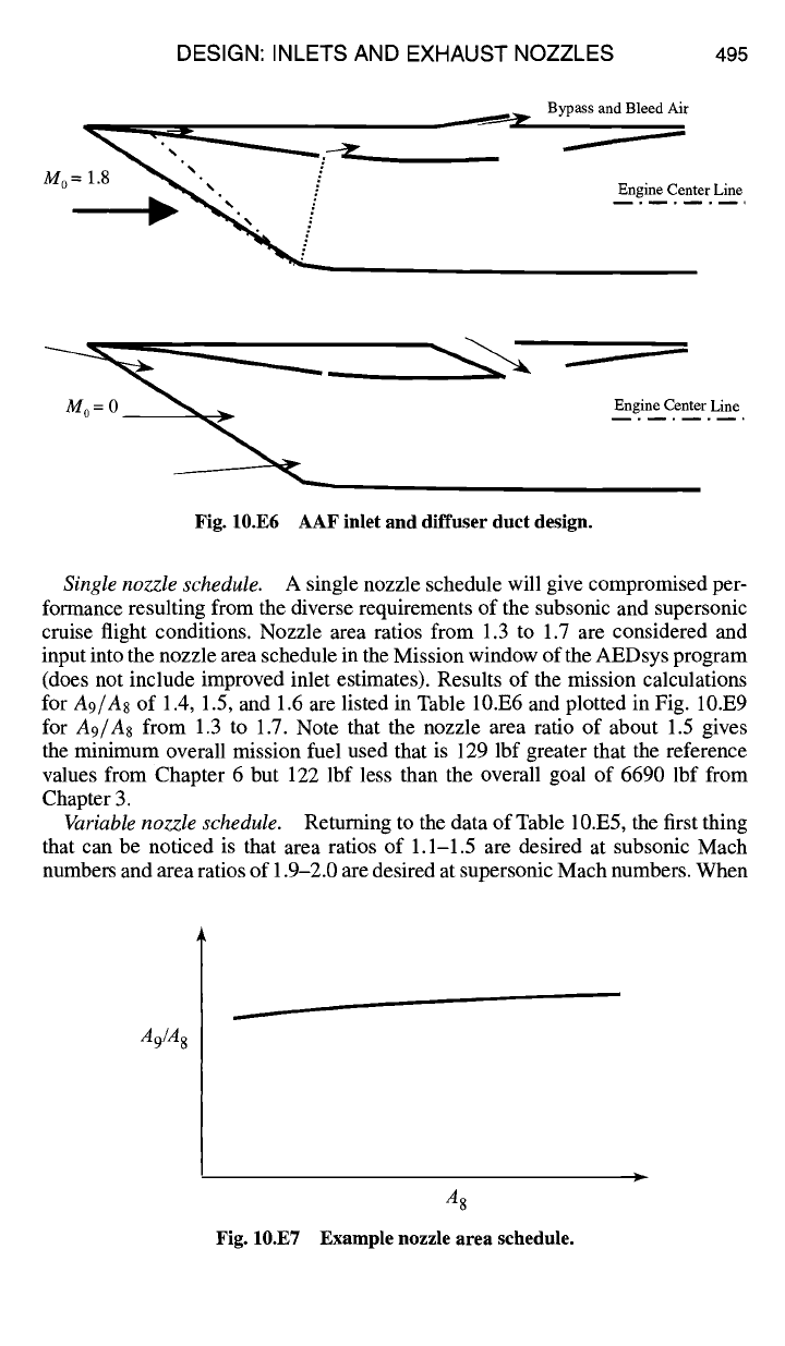
Figure 10.E6 shows the AAF inlet and diffuser duct design at two extreme flight
conditions, takeoff and Mach 1.8 operation. Note the change in function of the top
door from an auxiliary inlet at takeoff and low Mach number to a bypass exit for
supersonic flight conditions.
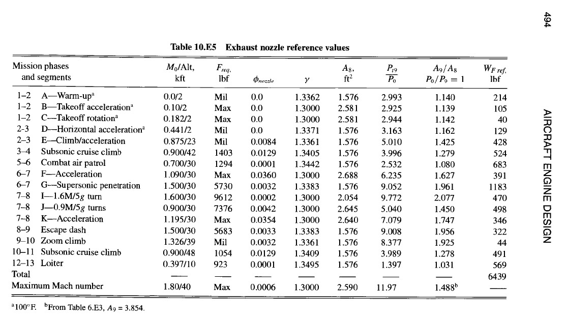
10.4.2 Exhaust Nozzle Design--AAF Engine
The performance of the exhaust nozzle was modeled by one-dimensional adia-
batic flow with constant total pressure ratio (zrn) for both the parametric and per-
formance cycle analyses of the AAF engine. Also, the nozzle area ratio (A9/A8)
and nozzle installation loss (q~nozzte) at each flight condition were based on ideal
expansion (P9/Po = 1). The results of these preceding analyses are listed in
Table 10.E5 for reference and serve as a starting point in the design of the AAF
exhaust nozzle. The preliminary design of the AAF exhaust nozzle involves se-
lection of the nozzle area schedule, design of the nozzle geometry, estimation of
nozzle performance based on gross thrust coefficient, and determination of the
installation losses.
10.4.2.1 Nozzle area schedule. Providing the required throat area is a pri-
mary function of the nozzle control system. Working in conjunction with the after-
burner fuel control, powered actuators are used to position the walls of
the nozzle as shown in Fig. 10.61 to provide the desired nozzle throat area (A8).
The walls of the divergent section are mechanically linked to the remainder of the
nozzle and thus the nozzle exit
area (A9)
is determined by this linkage. The net
effect of the actuator and linkage is an area ratio schedule for the exhaust nozzle
like that shown in Fig. 10.E7. The nozzle design that follows assumes that the
nozzle control system positions the nozzle throat at the required area (As). The
schedule of nozzle area ratio (A9/A8) will be selected for the AAE
The first task at hand is determining the desired nozzle schedule for the AAF
engine. The logical starting point is to plot the required nozzle area ratio (Ag/As)
versus throat area (A8) from the data of Table 10.E5 to see if there are any general
trends, as has been done in Fig. 10.ES. The mission flight legs that consume more
than 400 lbf fuel are marked with a square and a triangle is used for those legs
using less than 400 lbf fuel and these symbols are filled and unfilled for subsonic
and supersonic flight conditions, respectively. Notice that this plot (Fig. 10.E8) for
the AAF seems to be more of a random scattering of data points than a recognizable
pattern--however supersonic flight conditions do generally require larger nozzle
area ratios (A9/A8). A nozzle area ratio of about 1.28 is desired for subsonic
cruise and a value of 1.96 is desired for supersonic cruise. For simplicity, a single
value of the nozzle area ratio is first sought in the following section.
DESIGN: INLETS AND EXHAUST NOZZLES 493
=
.-~c4
oo~o~o~o~~o
ooooooooooooooooo
ooooooooooooooooo
~o~~o~o~o~
~oooo~o~ooo
Oooooo~oo~ooo~ooo
~oooo~o~ooo
oooo~o~oo~
Oooo~o~o~
O
i
- ~b4
r.~ {,,J ~,.
494 AIRCRAFT ENGINE DESIGN
_=
N
l
O O
II
~5
DESIGN: INLETS AND EXHAUST NOZZLES 495
M o = 1.8 • ...
Bypass and Bleed Air
Engine Center Line
Engine Center Line
Fig. 10.E6 AAF inlet and diffuser duct design.
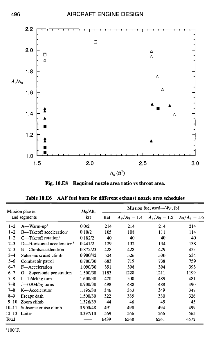
Single nozzle schedule.
A single nozzle schedule will give compromised per-
formance resulting from the diverse requirements of the subsonic and supersonic
cruise flight conditions. Nozzle area ratios from 1.3 to 1.7 are considered and
input into the nozzle area schedule in the Mission window of the AEDsys program
(does not include improved inlet estimates). Results of the mission calculations
for
A9/A8
of 1.4, 1.5, and 1.6 are listed in Table 10.E6 and plotted in Fig. 10.E9
for
A9/A8
from 1.3 to 1.7. Note that the nozzle area ratio of about 1.5 gives
the minimum overall mission fuel used that is 129 lbf greater that the reference
values from Chapter 6 but 122 lbf less than the overall goal of 6690 lbf from
Chapter 3.
Variable nozzle schedule.
Returning to the data of Table 10.E5, the first thing
that can be noticed is that area ratios of 1.1-1.5 are desired at subsonic Mach
numbers and area ratios of 1.9-2.0 are desired at supersonic Mach numbers. When
A9/A 8
Fig. 10.E7
A 8
Example nozzle area schedule.
496 AIRCRAFT ENGINE DESIGN
A#A8
2.2
2.0
1.8
1.6
1.4
1.2
1.0
1.5
' ' ' ' ' ' ' ' ' I ' ' ' ' ' ' ' ' '
A
A
A
A
t
ill i i i i i i i I i i i i i i I I I I i i i i i i i i i
2.0 2.5 3.0
A 8 (ft 2)
Fig. 10.E8 Required nozzle area ratio vs throat area.
Table 10.E6 AAF fuel burn for different exhaust nozzle area schedules
Mission phases M0/Alt,
and segments kft
Mission fuel used--WE, lbf
Ref
A9/A8
= 1.4
A9/A8
= 1.5
A9/A8
= 1.6
1-2 A--Warm-up a 0.0/2 214
1-2 B--Takeoff acceleration a 0.10/2 105
1-2 C--Takeoff rotation a 0.182/2 40
2-3 D--Horizontal acceleration a 0.441/2 129
2-3 E---Climb/acceleration 0.875/23 428
3-4 Subsonic cruise climb 0.900/42 524
5-6 Combat air patrol 0.700/30 683
6-7 F--Acceleration 1.090/30 391
6-7 G--Supersonic penetration 1.500/30 1183
7-8 I--1.6M/5g turn 1.600/30 470
7-8 J~.9M/5g tums 0.900/30 498
7-8 K--Acceleration 1.195/30 346
8-9 Escape dash 1.500/30 322
9-10 Zoom climb 1.326/39 44
10-11 Subsonic cruise climb 0.900/48 491
12-13 Loiter 0.397/10 569
Total 6439
214 214 214
108 111 114
40 40 40
132 134 138
428 429 433
526 530 534
719 738 759
398 394 393
1228 1211 1199
500 489 481
488 488 490
353 349 347
335 330 326
46 45 45
490 494 499
566 566 565
6568 6561 6572
alOO°E