Mattingly J.D., Heiser W.H., Pratt D.T. Aircraft Engine Design
Подождите немного. Документ загружается.

DESIGN: INLETS AND EXHAUST NOZZLES 477
and the ideal gross thrust (corresponds to (P9 = P0) expressed as
Fg ideal = ~18i Vs/gc
(10.31)
where Vs is the isentropic exit velocity based on
Pts/Po
and Tts. Please note that
the uninstalled gross thrust differs from the uninstalled thrust of Eq. (4.1) only by
the momentum of the incoming air, which is constant.
For one-dimensional flow of a calorically perfect gas, Eq. (10.30) can be written
as
/'hzV9 {1 +),--1 1--
Po/P9
} (10.32)
Fgactual-
g¢ 2y
(et9/-P9--) (×-1)/----~ - 1
The uninstalled gross thrust coefficient for one-dimensional flow of a calori-
cally perfect gas can be obtained by substituting Eqs. (10.31) and (10.32) into
Eq. (10.27), giving
1 - ~,sJ y - 1 1 - Po/P9
Cfg=CDCv 1 ~ 1+ -2-{ ~P9J 1
,~-2,8, ( p,9~--C- 1-7~ -- (10.33)
This equation reduces to
Cfg = CDCv
for the case of ideal expansion (P9 =
P9i = PO).
For isentropic flow, P9 =
P9i, et9 = Pt8, Cv
----
1, and
CD = 1.
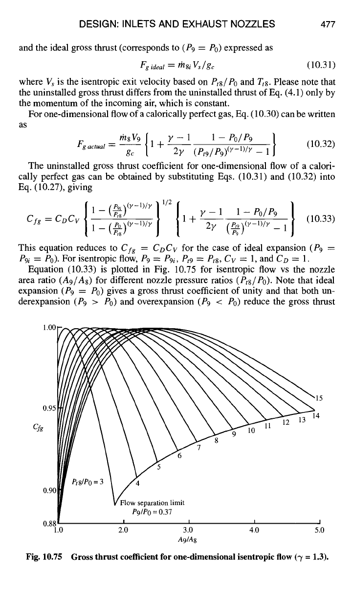
Equation (10.33) is plotted in Fig. 10.75 for isentropic flow vs the nozzle
area ratio
(A9/As)
for different nozzle pressure ratios
(Pts/Po).
Note that ideal
expansion (P9 ---- P0) gives a gross thrust coefficient of unity and that both un-
derexpansion (P9 > P0) and overexpansion (P9 < P0) reduce the gross thrust
1.00
0.95
Cy8
0.90
0.88
1.0
Fig. 10.75
Flow separation limit
P9/Po
= 0.37
I I I I
2.0 3.0 4.0 5.0
A9/A8
Gross thrust coefficient for one-dimensional isentropic flow (-y = 1.3).
478 AIRCRAFT ENGINE DESIGN
coefficient below unity. Both the uninstalled and installed thrust suffer as a result
of non-ideal expansion.
The extent of overexpansion in nozzles is limited by flow separation resulting
from the interaction of the nozzle boundary layer and the strong oblique shock
waves at the exit of the nozzle. In extreme overexpansion, Summerfield et al) 8
noted that the oblique shock waves moved from the exit lip into the nozzle, the
flow downstream of the shock waves was separated in the vicinity of the wall,
and as a result the wall static pressure downstream of the shock waves was nearly
equal to the ambient pressure (P0). A simple estimate for the maximum allowable
ratio of the pressure just preceding the shock waves
(Ps)
to the ambient pressure
(P0), suggested by Summerfield, is given by
Ps / Po "~
0.37 (10.34)
This flow separation limit can be included in the one-dimensional gross thrust co-
efficient of Eq. (10.33) for isentropic flow by considering the effective exit pressure
(P9 =
P9i)
to be the pressure just preceding the shock wave
(Ps).
Equations (10.33)
and (10.34) were used to obtain the flow separation limit shown on Fig. 10.75. The
design area ratio
(A9/A8)
of convergent-divergent nozzles is selected such that the
nozzle flow does not separate due to overexpansion for most throttle settings. This
is because the increase in gross thrust coefficient associated with flow separation
does not normally offset the accompanying increase in installation loss.
Nozzle pressure ratios are 3-5 in the subsonic cruise speed range of turbofan and
turbojet engines. Typically, a subsonic engine uses a convergent exhaust nozzle.
This is because, in the 3-5 nozzle pressure range, the convergent nozzle gross thrust
(intercept of lines with vertical axis,
A9/A8
= 1) is 1-3% below the peak gross
thrust (P9 = P0) as shown in Fig. 10.75. Consequently, there may be insufficient
gross thrust increase available in going to a convergent-divergent nozzle on a
subsonic cruise turbofan or turbojet engine to pay for the added drag and weight
of such a nozzle. In some applications, this loss in gross thrust coefficient of a
convergent nozzle is too much and a C-D nozzle is used.
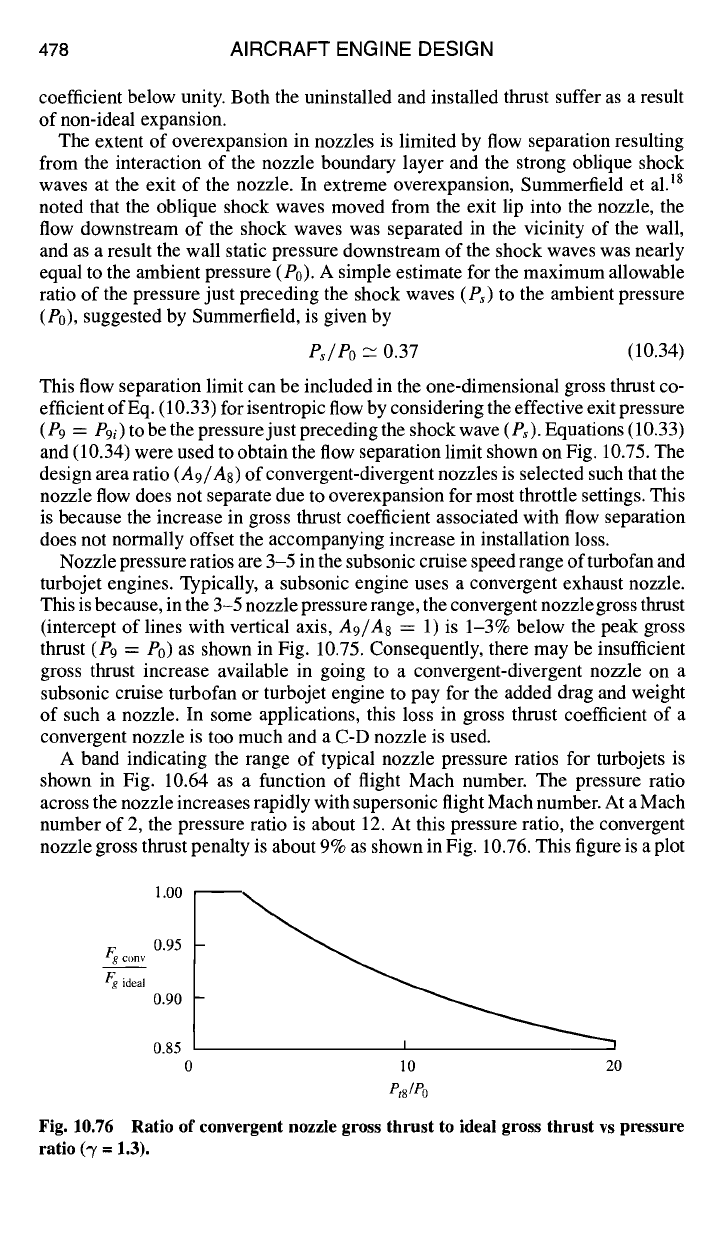
A band indicating the range of typical nozzle pressure ratios for turbojets is
shown in Fig. 10.64 as a function of flight Mach number. The pressure ratio
across the nozzle increases rapidly with supersonic flight Mach number. At a Mach
number of 2, the pressure ratio is about 12. At this pressure ratio, the convergent
nozzle gross thrust penalty is about 9% as shown in Fig. 10.76. This figure is a plot
Fg ..... 0.95
Egg ideal
0.90
0.85
0 10 20
P, smo
Fig. 10.76 Ratio of convergent nozzle gross thrust to ideal gross thrust vs pressure
ratio ('7 = 1.3).
DESIGN: INLETS AND EXHAUST NOZZLES 479
of the ratio of the gross thrust in Fig. 10.75 of a convergent nozzle
(A9/A8
= 1) to
the peak thrust (P9 = P0) vs
Pt8/Po.
Substitution of convergent-divergent nozzles
for convergent nozzles provides large thrust gains for supersonic aircraft.
This method of calculating the performance of a one-dimensional nozzle, as
demonstrated in the following example, is incorporated in the NOZZLE program
provided with the AEDsys software package.
10.3.3.3 Example calculation based on one-dimensional flow.
Given:
rh8 = 200 lbm/s
Pt8
= 30 psia Tt8 = 2000°R
A9/A8
= 2.0 y = 1.33 Po = 5 psia
Pt9/Pts
= 0.98 Co = 0.98
Rg c
= 1716 ft2/s2-°R
Find the dimensions of an axisymmetric nozzle,
Cfg, Fg,
and
Cv.
Solution:
From Gas Tables,
MFP(@M8
= 1) = 0.5224, thus A8 = 570.7 in. 2
With
CD =
0.98, thus
A8e =
582.3 in. 2 and r8 = 13.61 in.
Since
A9/A8
= 2.0, then A9 = 1165 in. 2 and r9 = 19.25 in.
9i e9i
A _ A9 _ 2.0 _ 2.041 =¢,
M9i =
2.168 and
Pt9i
A --2 Co-'A8 0.9~
= 0.0990
Thus,
P9i =
(0.0990)(30 psia) = 2.970 psia,
V9i = ~ -~. 1 -- k Pt9i/]
Vgi = ~/(1716)(2000)~2(1 33) {1 - (0.0990) °"33/1'33 } = 3475 ft/s
A _ Pt9
A9 _ 0.98 × 2.0 _ 2.00 ~ M9 2.146 and P9 0.1025
A* Pt8 CDA8
0.98
Pt9i
i
Thus P9 = (0.1025)(0.98)(30 psia) = 3.014 psia,
V9i
=
~/(1716)(2000)~2(1 33){1
-(0.1025) 0"33/1'33 } ~-
3456 ft/s
Cv = V9/V9i
= 0.9945
• [i (297]0.33/1.331
1/2[ 0.33 1 -- 5.0/3.014 /
Cfg =
(0.98)(0.9945)| 2-- ~ $ |1 -F (
29.4 ,~0.33/1.33
/
11-(~--~) " J | 2.66~, -1
C fg =
0.9593
480 AIRCRAFT ENGINE DESIGN
1- 54 in ~, 19.25 in
13.61 in l
__. Ce___nterli___n.e_._._._ .I
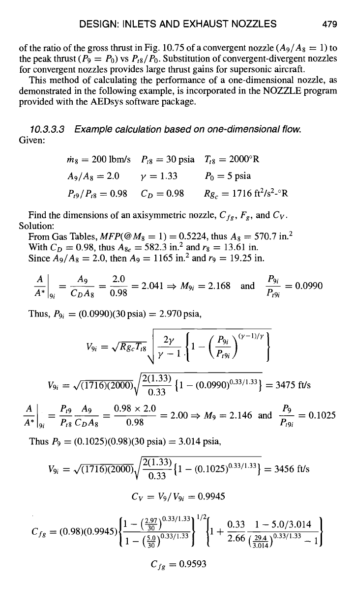
Fig. 10.77 Dimensions of example exhaust nozzle (one-dimensional calculation).
Figure 10.71b gives 0 ~ 10 deg for CD = 0.98 and
A9/As
= 2. Likewise,
Fig. 10.72 gives ot ~ 6 deg for
Cv
= 0.9945 and
A9/A8
= 2. Thus
Ls ~
54 in.
and the dimensions of the exhaust nozzle are shown in Fig. 10.77. The gross thrust
can be calculated several ways: directly from Eq. (10.30)
Fg = r'n8 V9/gc -}-
(P9 - Po)A9
Fg
= (200)(3456)/32.174 + (3.014 - 5.0) 1165 = 19,170 lbf
or from the ideal gross thrust and
Cfg
with
V, = x/(1716)(2000) ~ 1 - \~-~] ] = 3151 ft/s
then
Fgi = m8iVs/gc
= (200/0.98)(3151)/32.174 = 19,990 lbf
Fg = CfgFsi
= (0.9593)(19,990) = 19,170 lbf
10.3.3.4 General thrust performance.
The gross
thrust coefficient (Cfg)
is a measure of the nozzle efficiency and accounts for nozzle losses due to friction,
angularity, expansion, leakage and cooling air throttling.
Cfg
can be expressed in
terms of the other nozzle coefficients as
CvCArh7Vgi/gc + (P9i -
Po)A9
Cf~ = - ACfg
(10.35)
rh7 Vs/ gc
where
Cv =
CA =
l'h 7
V9i =
P9i
A9 =
~=
Velocity coefficient, Eq. (10.24)
Angularity coefficient, Eq. (10.29)
Actual total mass flow rate supplied to the nozzle
Ideal velocity at the nozzle exit based on
A9/As, CD,
and Tt8
Ideal static pressure at the nozzle exit consistent with
V9i
Nozzle physical exit area
Isentropic or fully expanded exit velocity based on
Pts/Po
and Tt8
The sum of the loss in thrust coefficient due to leakage
of gas from the nozzle and the loss due to changes in the
cooling air flow
DESIGN: INLETS AND EXHAUST NOZZLES 481
1.0
Angularity and
Cfgpeakf
~ Expan~sion t fricti°n l°ss
P t8/Po
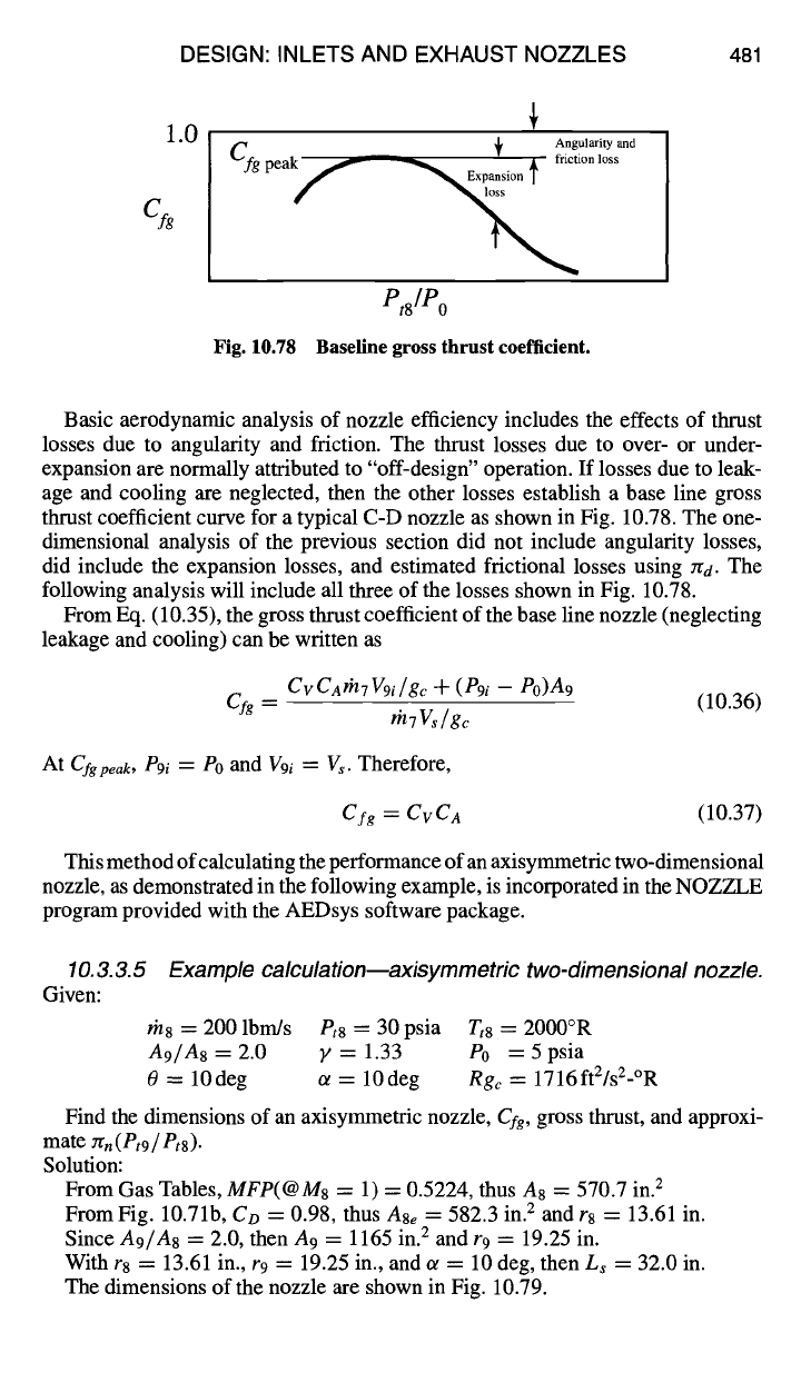
Fig. 10.78 Baseline gross thrust coefficient.
Basic aerodynamic analysis of nozzle efficiency includes the effects of thrust
losses due to angularity and friction. The thrust losses due to over- or under-
expansion are normally attributed to "off-design" operation. If losses due to leak-
age and cooling are neglected, then the other losses establish a base line gross
thrust coefficient curve for a typical C-D nozzle as shown in Fig. 10.78. The one-
dimensional analysis of the previous section did not include angularity losses,
did include the expansion losses, and estimated frictional losses using Zrd. The
following analysis will include all three of the losses shown in Fig. 10.78.
From Eq. (10.35), the gross thrust coefficient of the base line nozzle (neglecting
leakage and cooling) can be written as
CvC A#17 W9i / gc q- ( e9i -
Po)A9
Cfg
= (10.36)
rnTV,/g~
At
Cfgpeak , P9i ~" eo and V9i = Vs.
Therefore,
Cfg = CvC A
(10.37)
This method of calculating the performance of an axisymmetric two-dimensional
nozzle, as demonstrated in the following example, is incorporated in the NOZZLE
program provided with the AEDsys software package.
10.3.3.5 Example calculation--axisymmetric two-dimensional nozzle.
Given:
rh8 = 200 lbm/s
Pt8
= 30 psia Tt8 = 2000°R
A9/A8=2.0
y=1.33 P0 =5psia
0 = 10deg a = 10deg
Rgc
= 1716ftZ/sZ-°R
Find the dimensions of an axisymmetric nozzle,
Cfg,
gross thrust, and approxi-
mate
zrn( Pt9 / Pts).
Solution:
From Gas Tables,
MFP(@M8
= 1) = 0.5224, thus A8 = 570.7 in. 2
From Fig. 10.71b,
Co
= 0.98, thus
A8e
= 582.3 in. 2 and r8 = 13.61 in.
Since
A9/A8
= 2.0, then A9 = 1165 in. 2 and r 9
=
19.25 in.
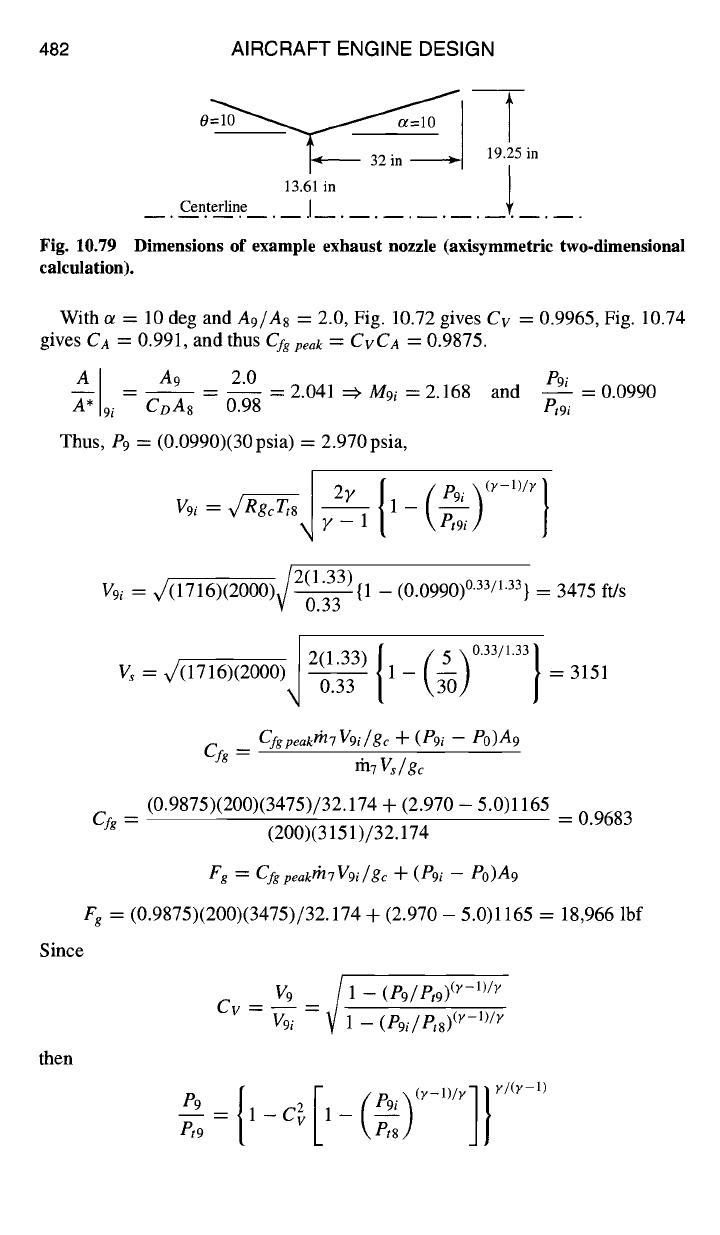
With r8 = 13.61 in., r9 = 19.25 in., and ot = 10 deg, then Ls = 32.0 in.
The dimensions of the nozzle are shown in Fig. 10.79.
482 AIRCRAFT ENGINE DESIGN
13.61 in
Centerline j
19.25 in
Fig. 10.79 Dimensions of example exhaust nozzle (axisymmetric two.dimensional
calculation).
With a = 10 deg and
A9/A8
= 2.0, Fig. 10.72 gives
Cv
= 0.9965, Fig. 10.74
gives
CA
= 0.991, and thus
Cfg
peak = CvCa
=
0.9875.
9i e9i
AA, -- CoA 8A9
-- 0.982"0 _ 2.041
=~
M9i
= 2.168 and
et9i
Thus, P9 = (0.0990)(30 psia) = 2.970 psia,
V9i = ~ ~ 1 - kPt9i/]
= 0.0990
V9i = ~f(1716)(2000)~/~2(1 33){1
- (0.0990) 0'33/1'33 } =
3475 ft/s
Since
then
I =(,.~) { (~ ~°"~"" I
Vs = ~(1716)(2000) ~ 1 - \3-0] / = 3151
Cfg = Cfgpeakth7V9i/gc + (P9i -
eo)A9
fnTVs/ge
(0.9875)(200)(3475)/32.174 + (2.970 - 5.0)1165
Cfg
= = 0.9683
(200)(3151)/32.174
Fg = C fg peakth 7 V9i / ge ÷ ( P9i -
Po)A9
Fg
= (0.9875)(200)(3475)/32.174 + (2.970 - 5.0)1165 = 18,966 lbf
Cv-
/ p,
,p ~(y-1)/y
V 9
--
.1- ( 9/ t9J
Vgi V 1 - (Pgi/Pts) O'-W×
_ j}
DESIGN: INLETS AND EXHAUST NOZZLES 483
1.05
S/Smin
1.00
1.00
F/F ma x
0.95 ~ I
0.5 1.0 1.5 2.0
Po/P9
Fig. 10.80 Effect of
Po/P 9
on
engine performance.
and
P9 = { 1 - (0.9965) 2 [1 - (0.0990)°"33/133]} 1'33/°'33 = 0.1012
Thus, M9 = 2.154,
A/A*I9
= 2.014 and, finally, from one-dimensional flow,
et9 A/A*[9
2.014
n'n -- -- Co-- -- (0.98) = 0.9867
Pt8 A9/As 2
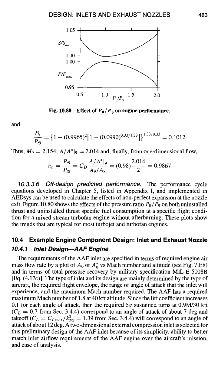
10.3.3.6 Off-design predicted performance.
The performance cycle
equations developed in Chapter 5, listed in Appendix I, and implemented in
AEDsys can be used to calculate the effects of non-perfect expansion at the nozzle
exit. Figure 10.80 shows the effects of the pressure ratio
Po/P9
on both uninstalled
thrust and uninstalled thrust specific fuel consumption at a specific flight condi-
tion for a mixed-stream turbofan engine without afterburning. These plots show
the trends that are typical for most turbojet and turbofan engines.
10.4 Example Engine Component Design: Inlet and Exhaust Nozzle
10.4.1 Inlet DesignEAAF Engine
The requirements of the AAF inlet are specified in terms of required engine air
mass flow rate by a plot of A0 or A~ vs Mach number and altitude (see Fig. 7.E8)
and in terms of total pressure recovery by military specification MIL-E-5008B
[Eq. (4.12c)]. The type of inlet and its design are mainly determined by the type of
aircraft, the required flight envelope, the range of angle of attack that the inlet will
experience, and the maximum Mach number required. The AAF has a required
maximum Mach number of 1.8 at 40 kft altitude. Since the lift coefficient increases
0.1 for each angle of attack, then the required 5g sustained turns at 0.9M/30 kft
(CL = 0.7 from Sec. 3.4.4) correspond to an angle of attack of about 7 deg and
takeoff (CL
=
CLmax/k20
=
1.39 from Sec. 3.4.4) will correspond to an angle of
attack of about 12 deg. A two-dimensional external compression inlet is selected for
this preliminary design of the AAF inlet because of its simplicity, ability to better
match inlet airflow requirements of the AAF engine over the aircraft's mission,
and ease of analysis.
484 AIRCRAFT ENGINE DESIGN
3.8
3.6
3.4
Ao
3.2
(ft 2)
3.0
I
''''l''''l''''l''''l''''l''' 'I''''I''''
Ao i +pec
Oy? y
Ao
Margin
2.8
1.0 1.1 1.2 1.3 1.4 1.5 1.6 1.7 1.8
M0
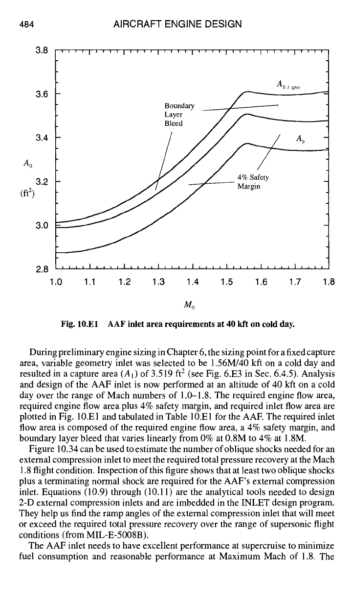
Fig. 10.El AAF inlet area requirements at 40 kft on cold day.
During preliminary engine sizing in Chapter 6, the sizing point for a fixed capture
area, variable geometry inlet was selected to be 1.56M/40 kfl on a cold day and
resulted in a capture area (A 1 ) of 3.519 ft 2 (see Fig. 6.E3 in Sec. 6.4.5). Analysis
and design of the AAF inlet is now performed at an altitude of 40 kft on a cold
day over the range of Mach numbers of 1.0-1.8. The required engine flow area,
required engine flow area plus 4% safety margin, and required inlet flow area are
plotted in Fig. 10.El and tabulated in Table 10.El for the AAF. The required inlet
flow area is composed of the required engine flow area, a 4% safety margin, and
boundary layer bleed that varies linearly from 0% at 0.8M to 4% at 1.8M.
Figure 10.34 can be used to estimate the number of oblique shocks needed for an
external compression inlet to meet the required total pressure recovery at the Mach
1.8 flight condition. Inspection of this figure shows that at least two oblique shocks
plus a terminating normal shock are required for the AAF's external compression
inlet. Equations (10.9) through (10.11) are the analytical tools needed to design
2-D external compression inlets and are imbedded in the INLET design program.
They help us find the ramp angles of the external compression inlet that will meet
or exceed the required total pressure recovery over the range of supersonic flight
conditions (from MIL-E-5008B).
The AAF inlet needs to have excellent performance at supercruise to minimize
fuel consumption and reasonable performance at Maximum Mach of 1.8. The
DESIGN: INLETS AND EXHAUST NOZZLES
Table 10.El AAF inlet area requirements at 40 kft on cold day
485
Inlet requirements based on engine
performance cycle analysis calculations
Inlet area modified for safety
margin and boundary layer bleed
mo ORspec
Aospec,
ft2
Aospec +
4%,
ft 2
Aotspec,
ft2
1.0 1.0000 2.874 2.989 3.012
1.1 0.9966 2.889 3.005 3.039
1.2 0.9915 2.940 3.058 3.105
1.3 0.9852 3.025 3.146 3.207
1.4 0.9782 3.142 3.268 3.343
1.5 0.9706 3.290 3.422 3.514
1.52 0.9690 3.322 3.455 3.551
1.54 0.9674 3.357 3.491 3.591
1.56 0.9657 3.373 3.508 3.611
1.58 0.9641 3.365 3.500 3.605
1.6 0.9624 3.359 3.493 3.601
1.7 0.9537 3.341 3.475 3.595
1.8 0.9445 3.344 3.478 3.612
ramp angles of the AAF inlet will be designed for performance at supercruise
and the inlet sized to meet the mass flow requirements over the range of flight
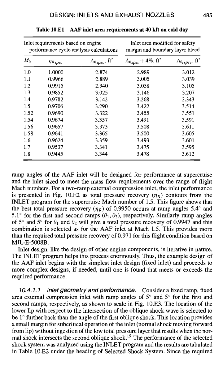
Mach numbers. For a two-ramp external compression inlet, the inlet performance
is presented in Fig. 10.E2 as total pressure recovery (OR) contours from the
INLET program for the supercruise Mach number of 1.5. This figure shows that
the best total pressure recovery (OR) of 0.9950 occurs at ramp angles 5.4 ° and
5.1 ° for the first and second ramps
(01, Oz),
respectively. Similarly ramp angles
of 5 ° and 5 ° for 01 and 02 will give a total pressure recovery of 0.9947 and this
combination is selected as for the AAF inlet at Mach 1.5. This provides more
than the required total pressure recovery of 0.971 for this flight condition based on
MIL-E-5008B.
Inlet design, like the design of other engine components, is iterative in nature.
The INLET program helps this process enormously. Thus, the example design of
the AAF inlet begins with the simplest inlet design (fixed inlet) and proceeds to
more complex designs, if needed, until one is found that meets or exceeds the
required performance.
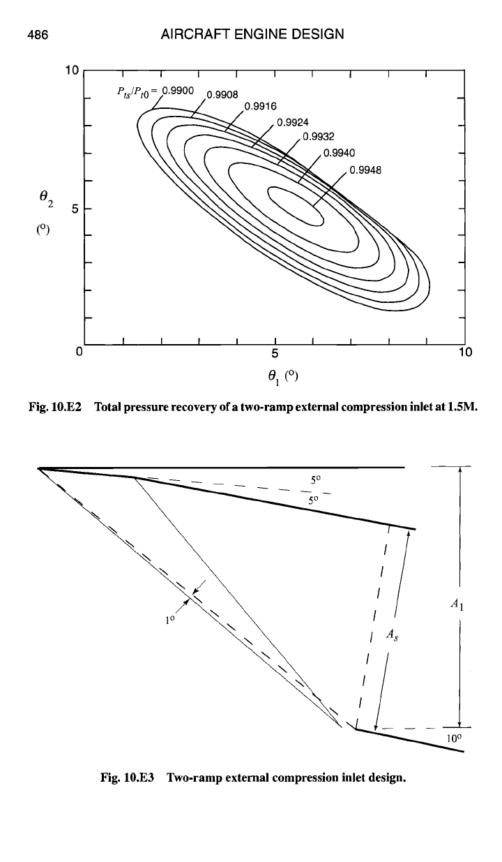
10.4.1.1 Inlet geometry and performance.
Consider a fixed ramp, fixed
area external compression inlet with ramp angles of 5 ° and 5 ° for the first and
second ramps, respectively, as shown to scale in Fig. 10.E3. The location of the
lower lip with respect to the intersection of the oblique shock wave is selected to
be 1 ° further back than the angle of the first oblique shock. This location provides
a small margin for subcritical operation of the inlet (normal shock moving forward
from lip) without ingestion of the low total pressure layer that results when the nor-
mal shock intersects the second oblique shock) 9 The performance of the selected
shock system was analyzed using the INLET program and the results are tabulated
in Table 10.E2 under the heading of Selected Shock System. Since the required
486
10
02
5
(o)
AIRCRAFT ENGINE DESIGN
Fig. 10.E2
I I I I I I i I I
P~/P~~9080.9916
( F~
/0.992.
I I I I I I I I I
0 5 10
Ol (0)
Total pressure recovery of a two-ramp external compression inlet at 1.5M.
7
~\ ,/
A
~\ ,A '~~ ,
Fig. 10.E3 Two-ramp external compression inlet design.