Mattingly J.D., Heiser W.H., Pratt D.T. Aircraft Engine Design
Подождите немного. Документ загружается.

1.0
0.8
Subcritical
-
St~
0<
o 0.6
8
o 0.4
o
0.2
DESIGN: INLETS AND EXHAUST NOZZLES 447
~'~-- Critical
Supercritical
1.0
I
~,.
0 1.0
Inlet mass flow ratio
rhiffnl
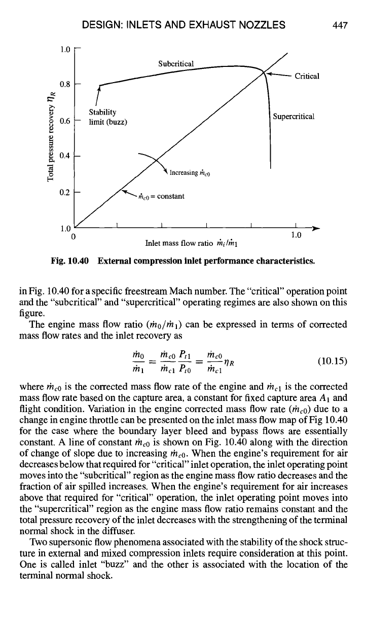
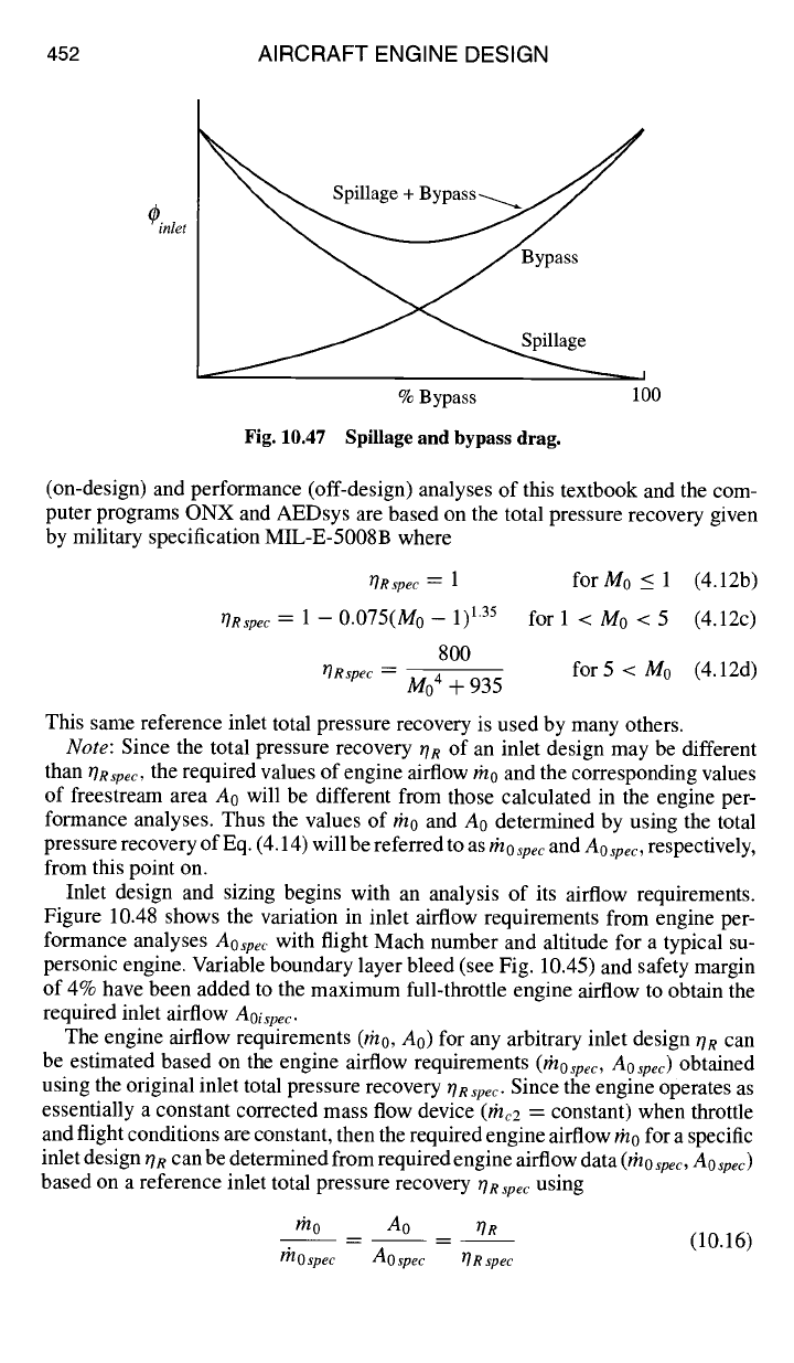
Fig. 10.40 External compression inlet performance characteristics.
in Fig. 10.40 for a specific freestream Mach number. The "critical" operation point
and the "subcritical" and "supercritical" operating regimes are also shown on this
figure.
The engine mass flow ratio (rh0/rhl) can be expressed in terms of corrected
mass flow rates and the inlet recovery as
mo m~o Ptl moo
.... r/R (10.15)
?i'll ~'tel Pt0 t~tcl
where rhc0 is the corrected mass flow rate of the engine and
?~'tcl
is the corrected
mass flow rate based on the capture area, a constant for fixed capture area A1 and
flight condition. Variation in the engine corrected mass flow rate (rhc0) due to a
change in engine throttle can be presented on the inlet mass flow map of Fig 10.40
for the case where the boundary layer bleed and bypass flows are essentially
constant. A line of constant the0 is shown on Fig. 10.40 along with the direction
of change of slope due to increasing rhc0. When the engine's requirement for air
decreases below that required for "critical" inlet operation, the inlet operating point
moves into the "subcritical" region as the engine mass flow ratio decreases and the
fraction of air spilled increases. When the engine's requirement for air increases
above that required for "critical" operation, the inlet operating point moves into
the "supercritical" region as the engine mass flow ratio remains constant and the
total pressure recovery of the inlet decreases with the strengthening of the terminal
normal shock in the diffuser.
Two supersonic flow phenomena associated with the stability of the shock struc-
ture in external and mixed compression inlets require consideration at this point.
One is called inlet "buzz" and the other is associated with the location of the
terminal normal shock.
448 AIRCRAFT ENGINE DESIGN
,* ~ Spilled airflow
•
_..._._----
°
• f
J
• / • Choked flow
• J
Normal shock , ..- .t
....~ ~ Separated
boundary layer
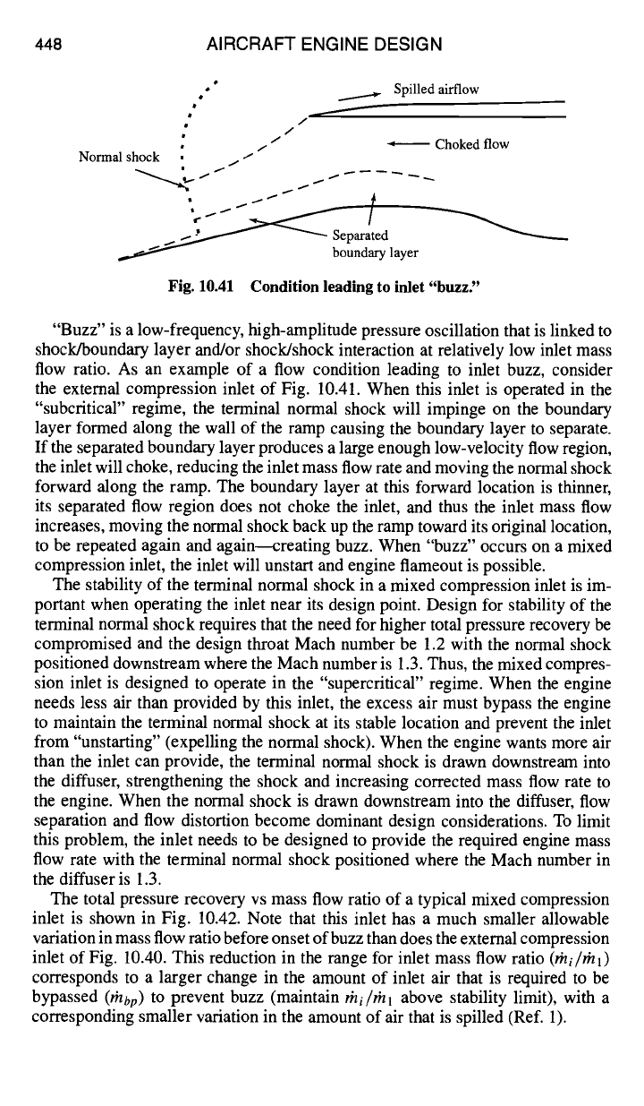
Fig. 10.41 Condition leading to inlet "buzz"
"Buzz" is a low-frequency, high-amplitude pressure oscillation that is linked to
shock/boundary layer and/or shock/shock interaction at relatively low inlet mass
flow ratio. As an example of a flow condition leading to inlet buzz, consider
the external compression inlet of Fig. 10.41. When this inlet is operated in the
"subcriticar' regime, the terminal normal shock will impinge on the boundary
layer formed along the wall of the ramp causing the boundary layer to separate.
If the separated boundary layer produces a large enough low-velocity flow region,
the inlet will choke, reducing the inlet mass flow rate and moving the normal shock
forward along the ramp. The boundary layer at this forward location is thinner,
its separated flow region does not choke the inlet, and thus the inlet mass flow
increases, moving the normal shock back up the ramp toward its original location,
to be repeated again and again--creating buzz. When "buzz" occurs on a mixed
compression inlet, the inlet will unstart and engine flameout is possible.
The stability of the terminal normal shock in a mixed compression inlet is im-
portant when operating the inlet near its design point. Design for stability of the
terminal normal shock requires that the need for higher total pressure recovery be
compromised and the design throat Mach number be 1.2 with the normal shock
positioned downstream where the Mach number is 1.3. Thus, the mixed compres-
sion inlet is designed to operate in the "supercritical" regime. When the engine
needs less air than provided by this inlet, the excess air must bypass the engine
to maintain the terminal normal shock at its stable location and prevent the inlet
from "unstarting" (expelling the normal shock). When the engine wants more air
than the inlet can provide, the terminal normal shock is drawn downstream into
the diffuser, strengthening the shock and increasing corrected mass flow rate to
the engine. When the normal shock is drawn downstream into the diffuser, flow
separation and flow distortion become dominant design considerations. To limit
this problem, the inlet needs to be designed to provide the required engine mass
flow rate with the terminal normal shock positioned where the Mach number in
the diffuser is 1.3.
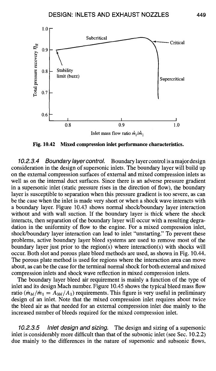
The total pressure recovery vs mass flow ratio of a typical mixed compression
inlet is shown in Fig. 10.42. Note that this inlet has a much smaller allowable
variation in mass flow ratio before onset of buzz than does the external compression
inlet of Fig. 10.40. This reduction in the range for inlet mass flow ratio
(rhi/rhl)
corresponds to a larger change in the amount of inlet air that is required to be
bypassed
(r~lbp)
to prevent buzz (maintain
#/i//#/1
above stability limit), with a
corresponding smaller variation in the amount of air that is spilled (Ref. 1).
DESIGN: INLETS AND EXHAUST NOZZLES 449
1.0
0.9
g
o
0.8
0.7
06-
Fig. 10.42
\
Stability
limit (buzz)
Subcritical
~-~'~"----- Critical
Supercritical
I I I
0.8 0.9 1.0
Inlet mass flow ratio
Yhi#h 1
Mixed compression inlet performance characteristics.
10.2.3.4 Boundary layer controL
Boundarylayercontrolisamajordesign
consideration in the design of supersonic inlets. The boundary layer will build up
on the external compression surfaces of external and mixed compression inlets as
well as on the internal duct surfaces. Since there is an adverse pressure gradient
in a supersonic inlet (static pressure rises in the direction of flow), the boundary
layer is susceptible to separation when this pressure gradient is too severe, as can
be the case when the inlet is made very short or when a shock wave interacts with
a boundary layer. Figure 10.43 shows normal shock/boundary layer interaction
without and with wall suction. If the boundary layer is thick where the shock
interacts, then separation of the boundary layer will occur with a resulting degra-
dation in the uniformity of flow to the engine. For a mixed compression inlet,
shock/boundary layer interaction can lead to inlet "unstarting." To prevent these
problems, active boundary layer bleed systems are used to remove most of the
boundary layer just prior to the region(s) where interaction(s) with shocks will
occur. Both slot and porous plate bleed methods are used, as shown in Fig. 10.44.
The porous plate method is used for regions where the interaction area can move
about, as can be the case for the terminal normal shock for both external and mixed
compression inlets and shock wave reflection in mixed compression inlets.
The boundary layer bleed air requirement is mainly a function of the type of
inlet and its design Mach number. Figure 10.45 shows the typical bleed mass flow
ratio
(rhbl/~nl = Aobt/A1)
requirements. This figure is very useful in preliminary
design of an inlet. Note that the mixed compression inlet requires about twice
the bleed air as that needed for an external compression inlet due mainly to the
increased number of bleeds required for the mixed compression inlet.
10.2.3.5 Inlet design and sizing.
The design and sizing of a supersonic
inlet is considerably more difficult than that of the subsonic inlet (see Sec. 10.2.2)
due mainly to the differences in the nature of supersonic and subsonic flows.

450 AIRCRAFT ENGINE DESIGN
~ Wall Boundary ~ Boundary Layer
S.ction
,, ~ Layer ~.~
~ ",~, ~ Supersonic ",,~~n~ ~
Obh'qu e__._.~$¢ ~, "~'~,,~
Shock t " , - ~ Boundary Layer
t -'~, Bleed-back e Normal
a a
Shock
I
Normal ¢
Shock #
a) Without Wall Suction b) With Wall
Suction
Fig. 10.43 Shock/boundary layer interaction: a) without wall suction; b) with wall
suction.
• • 00:00000
000
0000000000 O0
000000000 • •
000000 • •
Shock --...~•
Bleed Airflow "~
Shock --....~•
Airflow • • • Airflow
l~ i 1 1 ml 1 ~ i
Bleed Airflow
a) Slot Bleed b) Porous Bleed
Fig. 10.44 Boundary layer bleed methods: a) slot bleed; b) porous bleed.
A ob I/.41
0.16
0.12
0.08
0.04 -
0
0.8
Mixed Compression Inlets
mro.s ~...
I | i I I I I I
1.2 1.6 2 0 2.4 2.8 3.2 3.6 4.0
Mo
Fig. 10.45 Typical boundary layer bleed mass flow ratio?
DESIGN: INLETS AND EXHAUST NOZZLES 451
1.0
A~ ~ I ~ AO
I
T
Chapter 6
Inlet Airflow
Aoi req
A1
0.0
I I I I
0.5 1.0 1.5 2.0
M0
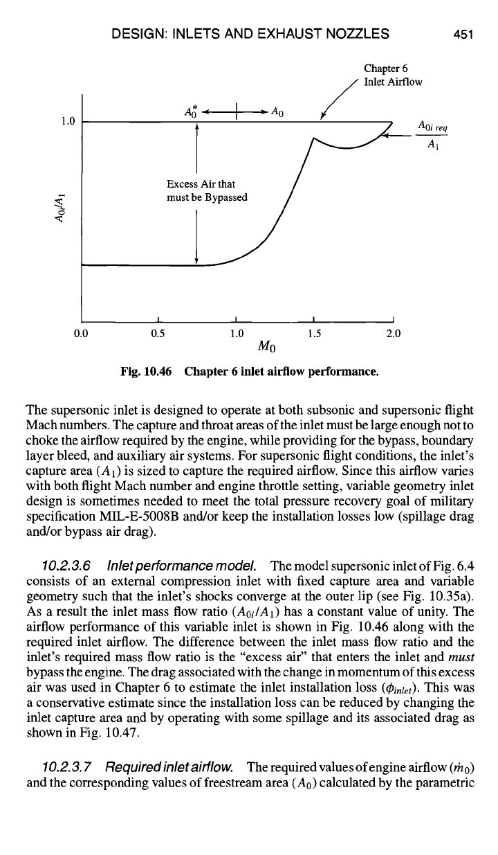
Fig. 10.46 Chapter 6 inlet airflow performance.
The supersonic inlet is designed to operate at both subsonic and supersonic flight
Mach numbers. The capture and throat areas of the inlet must be large enough not to
choke the airflow required by the engine, while providing for the bypass, boundary
layer bleed, and auxiliary air systems. For supersonic flight conditions, the inlet's
capture
area (A1)
is sized to capture the required airflow. Since this airflow varies
with both flight Mach number and engine throttle setting, variable geometry inlet
design is sometimes needed to meet the total pressure recovery goal of military
specification MIL-E-5008B and/or keep the installation losses low (spillage drag
and/or bypass air drag).
10.2.3.6 Inletpefformance model The model supersonic inlet of Fig. 6.4
consists of an external compression inlet with fixed capture area and variable
geometry such that the inlet's shocks converge at the outer lip (see Fig. 10.35a).
As a result the inlet mass flow ratio (Aoi/A1) has a constant value of unity. The
airflow performance of this variable inlet is shown in Fig. 10.46 along with the
required inlet airflow. The difference between the inlet mass flow ratio and the
inlet's required mass flow ratio is the "excess air" that enters the inlet and must
bypass the engine. The drag associated with the change in momentum of this excess
air was used in Chapter 6 to estimate the inlet installation loss
((9inlet).
This was
a conservative estimate since the installation loss can be reduced by changing the
inlet capture area and by operating with some spillage and its associated drag as
shown in Fig. 10.47.
10.2.3.7 Required inlet airflow. Therequiredvaluesofengineairflow(rh0)
and the corresponding values of freestream area (A0) calculated by the parametric
452 AIRCRAFT ENGINE DESIGN
~ntet
~ Bypass
% Bypass 100
Fig. 10.47 Spillage and bypass drag.
(on-design) and performance (off-design) analyses of this textbook and the com-
puter programs ONX and AEDsys are based on the total pressure recovery given
by military specification MIL-E-5008B where
ORspec
=
1 for M0 < 1 (4.12b)
ORspec
= 1 -- 0.075(M0 - 1) L35 for 1 < M0 < 5 (4.12c)
800
ORspec
M04 + 935
for 5 < M0 (4.12d)
This same reference inlet total pressure recovery is used by many others.
Note:
Since the total pressure recovery 0R of an inlet design may be different
than
ORspec,
the required values of engine airflow rh0 and the corresponding values
of freestream area A0 will be different from those calculated in the engine per-
formance analyses. Thus the values of rh0 and A0 determined by using the total
pressure recovery of Eq. (4.14) will be referred to as rn 0
spec
and
Ao spec,
respectively,
from this point on.
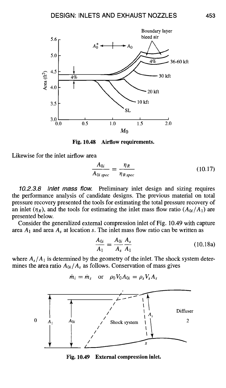
Inlet design and sizing begins with an analysis of its airflow requirements.
Figure 10.48 shows the variation in inlet airflow requirements from engine per-
formance analyses
Aospe c
with flight Mach number and altitude for a typical su-
personic engine. Variable boundary layer bleed (see Fig. 10.45) and safety margin
of 4% have been added to the maximum full-throttle engine airflow to obtain the
required inlet airflow
Aoispec.
The engine airflow requirements (rh0, A0) for any arbitrary inlet design 0R Can
be estimated based on the engine airflow requirements
(rhospec, Aospec)
obtained
using the original inlet total pressure recovery OR
wet.
Since the engine operates as
essentially a constant corrected mass flow device (rhc2 = constant) when throttle
and flight conditions are constant, then the required engine airflow rn0 for a specific
inlet design 0R can be determined from required engine airflow data (rno,pe¢,
Ao ~pec)
based on a reference inlet total pressure recovery OR
spec
using
rno A0 OR
..... (10.16)
/nospec Aospec ORspec
DESIGN: INLETS AND EXHAUST NOZZLES 453
5.6
5.0
4.5
~ 4.0
3.5
3.0
0.0
4%
o15
Boundary layer
bleed air
A~= [ ~A0~
J~~L...- --~ 36-60 kft
~.~,,,., ~t 30 I- /
~30kft
I
go
Fig. 10.48 Airflow requirements.
Likewise for the inlet airflow area
Aoi OR
- -- (10.17)
Aoi
spec T] R spec
10.2.3.8 Inlet mass flow.
Preliminary inlet design and sizing requires
the performance analysis of candidate designs. The previous material on total
pressure recovery presented the tools for estimating the total pressure recovery of
an inlet (OR), and the tools for estimating the inlet mass flow ratio (Aoi/A1) are
presented below.
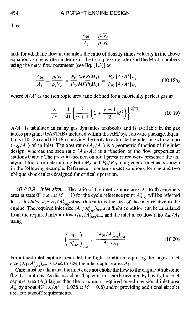
Consider the generalized extemal compression inlet of Fig. 10.49 with capture
area A1 and area As at location s. The inlet mass flow ratio can be written as
Aoi Aoi As
-- -- (10.18a)
A1 As A1
where As/A1 is determined by the geometry of the inlet. The shock system deter-
mines the area ratio Aoi/As as follows. Conservation of mass gives
/~/i "~- /~/s or
poVoAoi = psVsAs
T
A1
T / ~ I
/ I \ Diffuser
//
I
As
Aoi
/ Shock system I ~ 2
/ I
k___
// I
/ ~ ~
Fig. 10.49 External compression inlet.
454 AIRCRAFT ENGINE DESIGN
thus
Aoi Ps Vs
As Po Vo
and, for adiabatic flow in the inlet, the ratio of density times velocity in the above
equation can be written in terms of the total pressure ratio and the Mach numbers
using the mass flow parameter [see Eq. (1.3)] as
Aoi psVs Pt~ MFP(Ms) Pts [A/A*]M o
A~ poVo Pro MFP(Mo) Pro [A/A*]M~
(10.18b)
where
A/A*
is the isentropic area ratio defined for a calorically perfect gas as
y+l
A -- 1 {~+I(I+Y-IM2)}2(Yl) (10.19)
A* M 2
A/A*
is tabulated in many gas dynamics textbooks and is available in the gas
tables program (GASTAB) included within the AEDsys software package. Equa-
tions (10.18a) and (10.18b) provide the tools to estimate the inlet mass flow ratio
(Aoi/A1)
of an inlet. The area ratio
(As~A1)
is a geometric function of the inlet
design, whereas the area ratio
(Aoi/As)
is a function of the flow properties at
stations 0 and s.The previous section on total pressure recovery presented the an-
alytical tools for determining both Ms and
Pts/Pto
of a general inlet as is shown
in the following example. Reference 1 contains exact solutions for one and two
oblique shock inlets designed for critical operation.
10.2.3.9 Inlet sizo.
The ratio of the inlet capture area A1 to the engine's
area at state 0* (i.e., at M = 1) for the cycle reference point
A~ref
will be referred
to as the
inlet size Al/A~ref
since this ratio is the size of the inlet relative to the
engine. The required inlet size
(A 1/A~
ref)re q
at
a flight condition can be calculated
from the required inlet airflow
(Aoi/A~
ref)req
and the inlet mass flow ratio
Aoi/A1
using
A1) (Aoi/A~ref)req
= Aoi/A1
0 ref req
(10.20)
For a fixed inlet capture area inlet, the flight condition requiring the largest inlet
size
(A1/A~ ref)req
is used to size the inlet capture
area A1.
Care must be taken that the inlet does not choke the flow to the engine at subsonic
flight conditions. As discussed in Chapter 6, this can be assured by having the inlet
capture
area (A1)
larger than the maximum required one-dimensional inlet area
A~i
by about 4%
(A/A*
= 1.038 at M = 0.8) and/or providing additional air inlet
area for takeoff requirements.
DESIGN: INLETS AND EXHAUST NOZZLES 455
1.28
1.24
1.20
1.16
1.12
1.08
1.04
1.00
0.96
0.0
4%
l
I
0.5
A~-~
( Aoi "~
\Ao reI'T--]req
! __
y "-u
re]
I I I
1.0 1.5 2.0
Mo
Aoi spec
Ao ref
Fig. 10.50 Inlet airflow requirement for Example 10.2 inlet.
Example 10.2 External Compression Inlet (Part
II)
As an example, consider the fixed geometry, double ramp, external compression
inlet of Fig. 10.35 with 0a = 0b = 5 deg to be used with the engine whose required
airflow is plotted as
Ao/A*oref
in Fig. 10.50. These data are based on the airflow
requirements of Fig. 10.48 at 40 kft altitude and an
A~r e
of 4 22 ft 2 at sea-level
,f •
static conditions. The inlet is to be capable of operating up to Mach 2 at 40 kft
with efficient operation at Mach numbers less than 1.7. The inlet size and mass
flow characteristics of inlet and engine are required.
Inlet airflow requirements.
From performance (off-design) cycle calculations
based on the reference inlet recovery of military specification MIL-E-5008B, the
required full throttle engine mass flow ratio is given as
A o
spec/A~
ref
in Fig. 10.50.
Inspection of Fig. 10.50 shows that the most demanding mass flow requirements of
the inlet occur at altitudes above 36 kft. Increasing these values for boundary layer
bleed (0% at 0.8M, 4% at 2.0M. and linearly in between) and for safety margin
(4%) yields the required inlet mass flow ratio
Aospec/A1
(based on the reference
inlet recovery,
rlRspec )
times the inlet
size
Al/A~ref
or
Aoispec/A~ref.
Correcting
these data for the total pressure recovery OR of the inlet of interest (Table 10.1)
yields the required inlet performance
(Aoi/A~ ref)req"
Inlet performance.
The total pressure recovery of this inlet
(OR)
is tabulated
in Table 10.1, is plotted in Fig. 10.36, and was found to meet the requirement for
efficient total pressure recovery at Mach numbers less than 1.7. Analysis of the
mass flow characteristics of the inlet and engine are required before this inlet can
be sized. As long as the normal shock between stations b and c touches the lip of
the inlet, either station b or c of Fig. 10.35 can be equated to station s of Fig.10.49.
456 AIRCRAFT ENGINE DESIGN
Thus
and
Aoi Ptb [A/A*]Mo Ptc [A/A*]Mo
As Pro [A/A*]M b Pto [A/A*]M~
(10.21a)
Ptc Ptb ~R
-- = ~R; -- --
(lO.21b)
P,o P,o P~c/ P~b
The area ratio
(Aoi ~As)
can be calculated using the results of Table 10.1 assuming
that
Ms = Mb
at subsonic values Of Mb (no local flow acceleration or deceleration).
For subsonic M0, a reasonable approximation is for choked flow at station s and
thus
A~i = As.
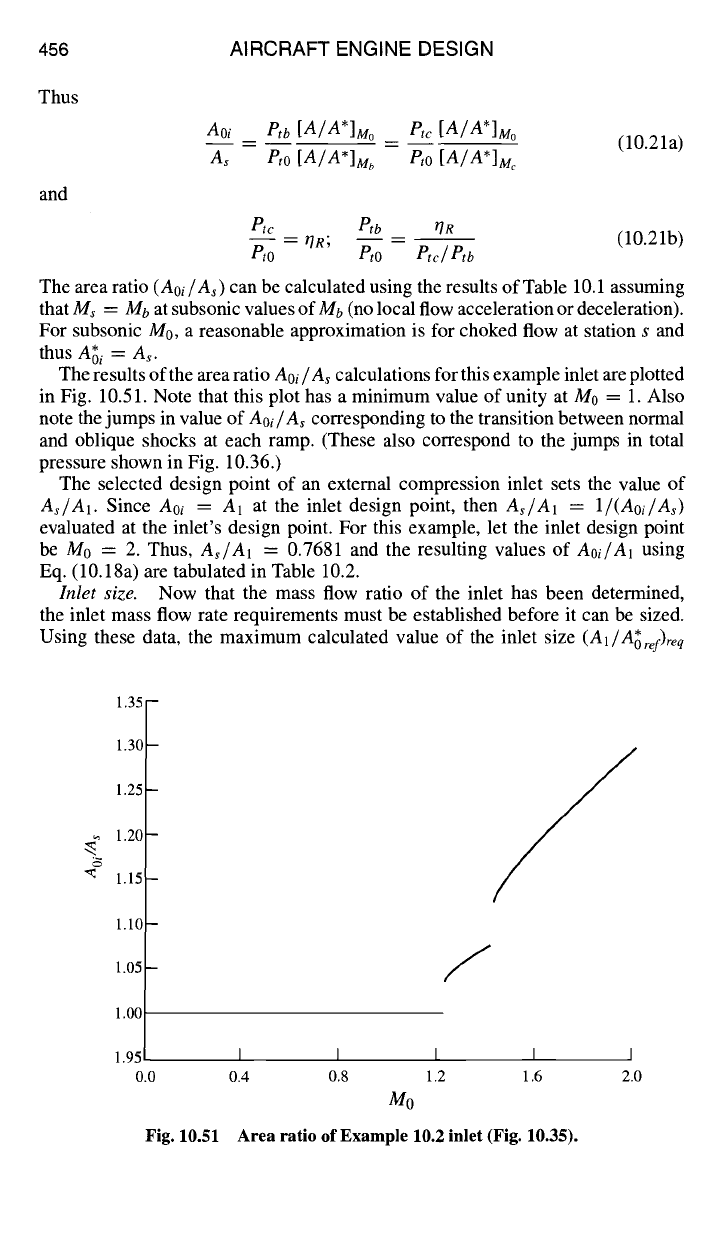
The results of the area ratio
Aoi/A s
calculations for this example inlet are plotted
in Fig. 10.51. Note that this plot has a minimum value of unity at M0 = 1. Also
note the jumps in value of
Aoi/As
corresponding to the transition between normal
and oblique shocks at each ramp. (These also correspond to the jumps in total
pressure shown in Fig. 10.36.)
The selected design point of an external compression inlet sets the value of
As~A1.
Since
Aoi
= A1
at the inlet design point, then
As~A1
= 1/(Aoi/As)
evaluated at the inlet's design point. For this example, let the inlet design point
be M0 = 2. Thus,
A,/A1
= 0.7681 and the resulting values of
Aoi/A1
using
Eq. (10.18a) are tabulated in Table 10.2.
Inlet size.
Now that the mass flow ratio of the inlet has been determined,
the inlet mass flow rate requirements must be established before it can be sized.
Using these data, the maximum calculated value of the inlet size
(A1/A~ref)req
~5
1.35 -
1.30 -
1.25 -
1.20 -
1.15 -
1.10 -
1.05 -
1.00
1.95
0.0
Fig. 10.51
/
I I I
0.4 0.8 1.2
Mo
Area ratio of Example 10.2 inlet (Fig. 10.35).
I I
1.6 2.0