Mattingly J.D., Heiser W.H., Pratt D.T. Aircraft Engine Design
Подождите немного. Документ загружается.

DESIGN: INLETS AND EXHAUST NOZZLES 457
Table 10.2 Example 10.2 inlet performance
Mo Aoi/AI Mo Aoi/A|
0.9 0.7749 1.5 0.8895
1.0 0.7681 1.6 0.9151
1.1 0.7885 1.7 0.9378
1.2 0.7688 1.8 0.9592
1.3 0.8125 1.9 0.9798
1.4 0.8267 2.0 1.0
from Eq. (10.20) sets the size of this fixed geometry inlet. Comparison of
Figs. 10.50 and 10.51 indicates that the two most demanding operating points
will most likely be at M0 = 1.23 and M0 = 1.42. Sizing calculations at these
two Mach numbers are presented in Table 10.3. The flight condition at M0 = 1.42
determines the inlet size as A1 :
1.425
A~ref.
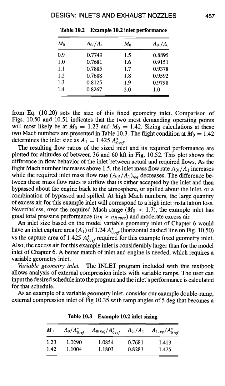
The resulting flow ratios of the sized inlet and its required performance are
plotted for altitudes of between 36 and 60 kft in Fig. 10.52. This plot shows the
difference in flow behavior of the inlet between actual and required flows. As the
flight Mach number increases above 1.5, the inlet mass flow rate
Aoi/A1
increases
while the required inlet mass flow rate
(Aoi/A1)req
decreases. The difference be-
tween these mass flow rates is airflow that is either accepted by the inlet and then
bypassed about the engine back to the atmosphere, or spilled about the inlet, or a
combination of bypassed and spilled. At high Mach numbers, the large quantity
of excess air for this example inlet will correspond to a high inlet installation loss.
Nevertheless, over the required Mach range (M0 < 1.7), the example inlet has
good total pressure performance (OR
>
rlRspec)
and moderate excess air.
An inlet size based on the model variable geometry inlet of Chapter 6 would
have an inlet capture area (A 1) of 1.24
A~ ref
(horizontal dashed line on Fig. 10.50)
vs the capture area of 1.425
A~ref
required for this example fixed geometry inlet.
Also, the excess air for this example inlet is considerably larger than for the model
inlet of Chapter 6. A better match of inlet and engine is needed, which requires a
variable geometry inlet.
Variable geometry inlet.
The INLET program included with this textbook
allows analysis of external compression inlets with variable ramps. The user can
input the desired schedule into the program and the inlet's performance is calculated
for that schedule.
As an example of a variable geometry inlet, consider our example double-ramp,
external compression inlet of Fig 10.35 with ramp angles of 5 deg that becomes a
Table 10.3 Example 10.2 inlet sizing
A*
Mo Ao/A~ref Aoireq/A~ref Aoi/A1 A1 req/ oref
1.23 1.0290 1.0854 0.7681 1.413
1.42 1.1004 1.1803 0.8283 1.425
458
1.05
1.00
0.95
0.90
"~ 0.85
0.80
0.75
0.70
0
Fig. 10.52
throttle.
A* 0 . I
I
=
AO
Aoi /A 1
Aoi
AIRCRAFT ENGINE DESIGN
req]A l
I I I I I
0.4 0.8 1.2 1.6 2
Mo
Mass flow performance of sized Example 10.2 inlet at altitude and full
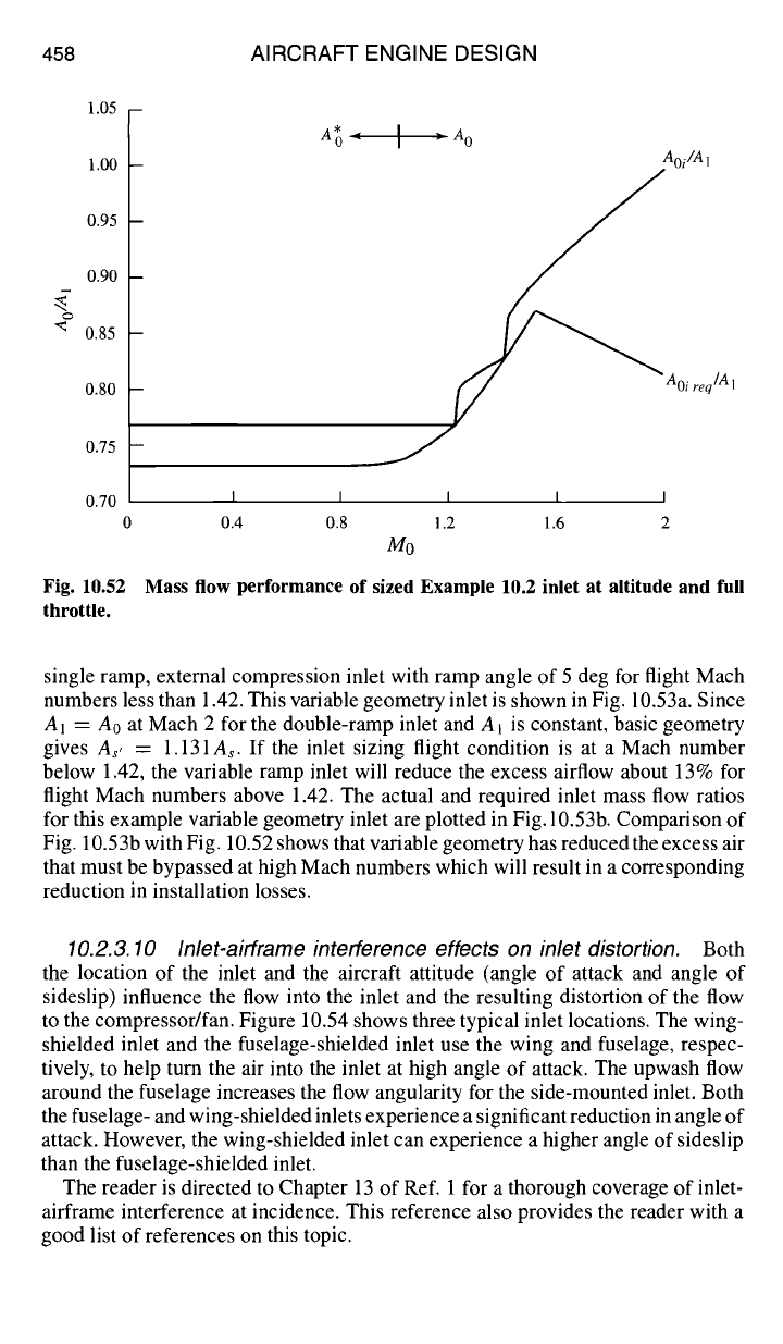
single ramp, external compression inlet with ramp angle of 5 deg for flight Mach
numbers less than 1.42. This variable geometry inlet is shown in Fig. 10.53a. Since
AI = A0 at Mach 2 for the double-ramp inlet and A~ is constant, basic geometry
gives As, = 1.131As. If the inlet sizing flight condition is at a Mach number
below 1.42, the variable ramp inlet will reduce the excess airflow about 13% for
flight Mach numbers above 1.42. The actual and required inlet mass flow ratios
for this example variable geometry inlet are plotted in Fig. 10.53b. Comparison of
Fig. 10.53b with Fig. 10.52 shows that variable geometry has reduced the excess air
that must be bypassed at high Mach numbers which will result in a corresponding
reduction in installation losses.
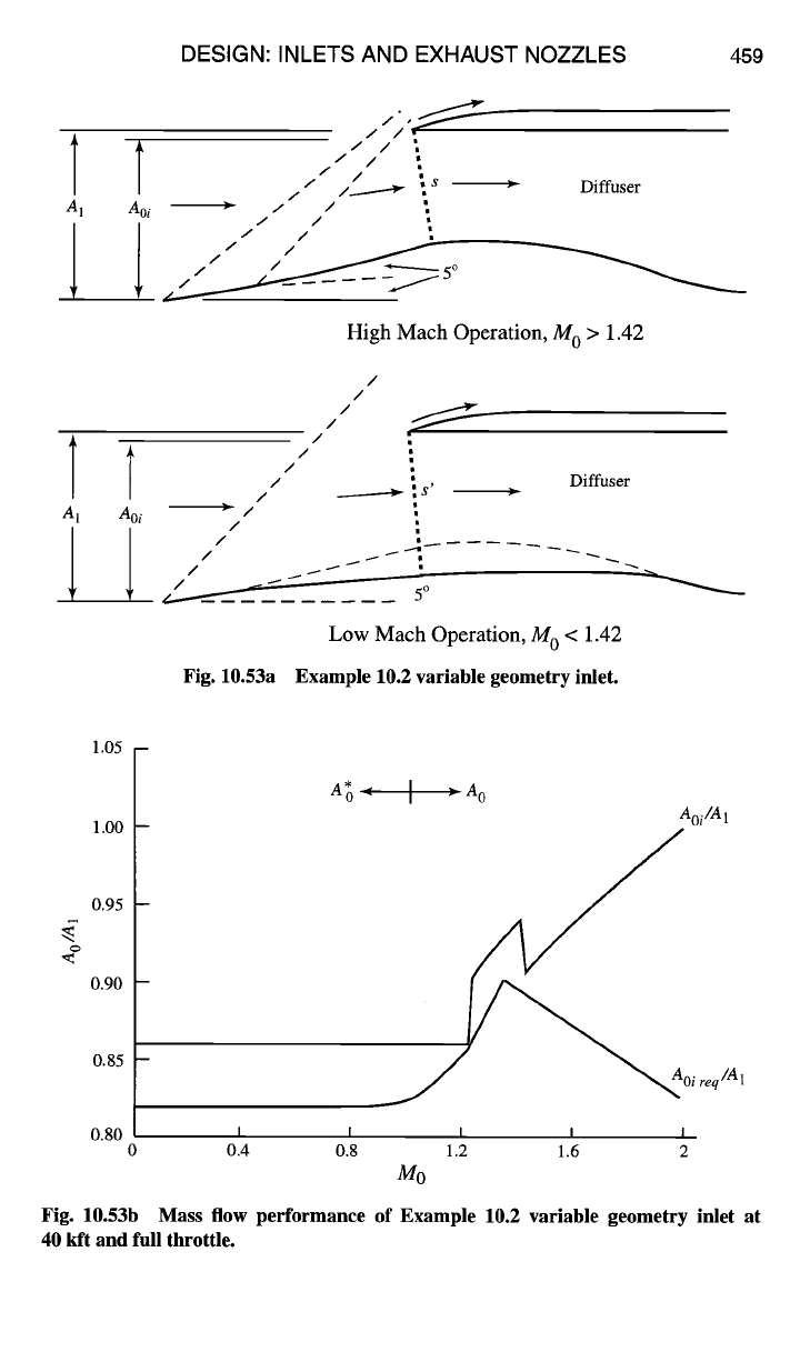
10.2.3. 10 Inlet-airframe interference effects on inlet distortion. Both
the location of the inlet and the aircraft attitude (angle of attack and angle of
sideslip) influence the flow into the inlet and the resulting distortion of the flow
to the compressor/fan. Figure 10.54 shows three typical inlet locations. The wing-
shielded inlet and the fuselage-shielded inlet use the wing and fuselage, respec-
tively, to help turn the air into the inlet at high angle of attack. The upwash flow
around the fuselage increases the flow angularity for the side-mounted inlet. Both
the fuselage- and wing-shielded inlets experience a significant reduction in angle of
attack. However, the wing-shielded inlet can experience a higher angle of sideslip
than the fuselage-shielded inlet.
The reader is directed to Chapter 13 of Ref. 1 for a thorough coverage of inlet-
airframe interference at incidence. This reference also provides the reader with a
good list of references on this topic.
DESIGN: INLETS AND EXHAUST NOZZLES 459
A
A
/ /
ii I ;s
Aoi • I I ",
I I
l / I ;
• Diffuser
High Mach Operation, M o > 1.42
/
/
/
/
/
i °
/ _.____--~ ~ s'
Aoi ~ I ~,
i ,
I
....t
i ~ °
Fig. 10.53a
Diffuser
Low Mach Operation, M 0 < 1.42
Example 10.2 variable geometry inlet.
1.05 -
1.00
0.95
0.90
0.85
0.80
A*O
I ~
AO
I
Aoi /A1
Oi req /A 1
I I I I I
0.4 0.8 1.2 1.6 2
Mo
Fig. 10.53b Mass flow performance of Example 10.2 variable geometry inlet at
40 kft and full
throttle.
460 AIRCRAFT ENGINE DESIGN
SIDE-MOUNTED WING-SHIELDED
FUSELAGE-SHIELDED
Fig. 10.54 Three typical inlet locations? °
10.2.3.11 Subsonic diffuser.
The subsonic diffuser portion of a subsonic
or supersonic inlet must provide a smooth transition from the conditions at the
inlet throat to those required at the face of the fan or compressor with minimal
flow distortion and total pressure loss. In addition to a smooth variation in flow
velocity, the diffuser may be required to transition from a rectangular cross-section
to a circular one and/or to offset the flow when the inlet and engine are not aligned.
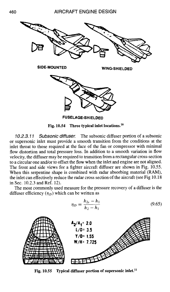
The front and side views for a fighter aircraft diffuser are shown in Fig. 10.55.
When this serpentine shape is combined with radar absorbing material (RAM),
the inlet can effectively reduce the radar cross section of the aircraft (see Fig 10.18
in Sec. 10.2.3 and Ref. 12).
The most commonly used measure for the pressure recovery of a diffuser is the
diffuser efficiency (r/D) which can be written as
h2~ - hi
r/D -- (9.65)
h2 -hi
A2/AI =
2.0
L/O--
3.5
v/o r ,is
Fig. 10.55 Typical diffuser portion of supersonic inlet, u
DESIGN: INLETS AND EXHAUST NOZZLES 461
where the subscript 1 denotes the entry of the diffuser and 2 denotes the exit. A
typical range of values for 7o is 0.80-0.95 which corresponds to total pressure
ratios
(Pte/Pti)
of 0.92-0.98 for
Mi
= 0.8.
Although the flow through the diffuser is very complex with possible flow
separation (see Fig. 9.21) in the regions of adverse pressure gradients, basic one-
dimensional gas dynamic analysis will yield useful and meaningful results. When
these results are incorporated with the diffuser efficiency, the overall performance
of a diffuser design can be estimated.
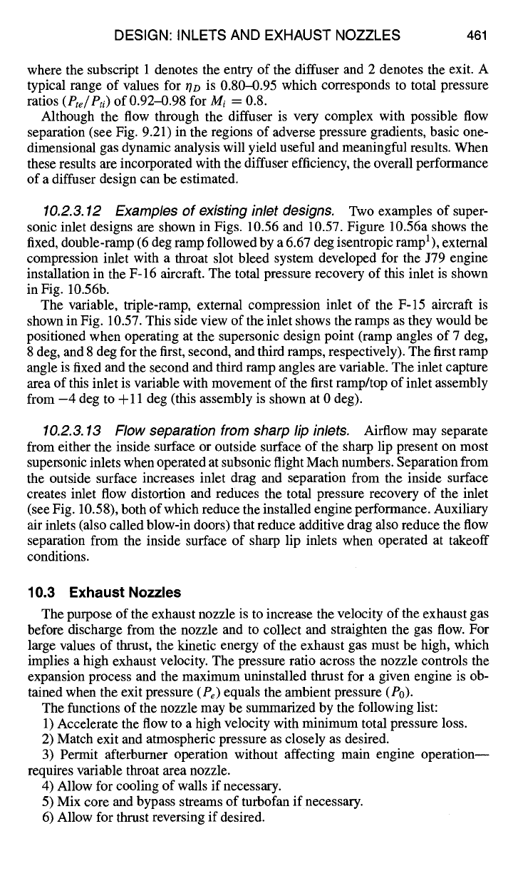
10.2.3.12 Examples of existing inlet designs.
Two examples of super-
sonic inlet designs are shown in Figs. 10.56 and 10.57. Figure 10.56a shows the
fixed, double-ramp (6 deg ramp followed by a 6.67 deg isentropic ramp 1), external
compression inlet with a throat slot bleed system developed for the J79 engine
installation in the F-16 aircraft. The total pressure recovery of this inlet is shown
in Fig. 10.56b.
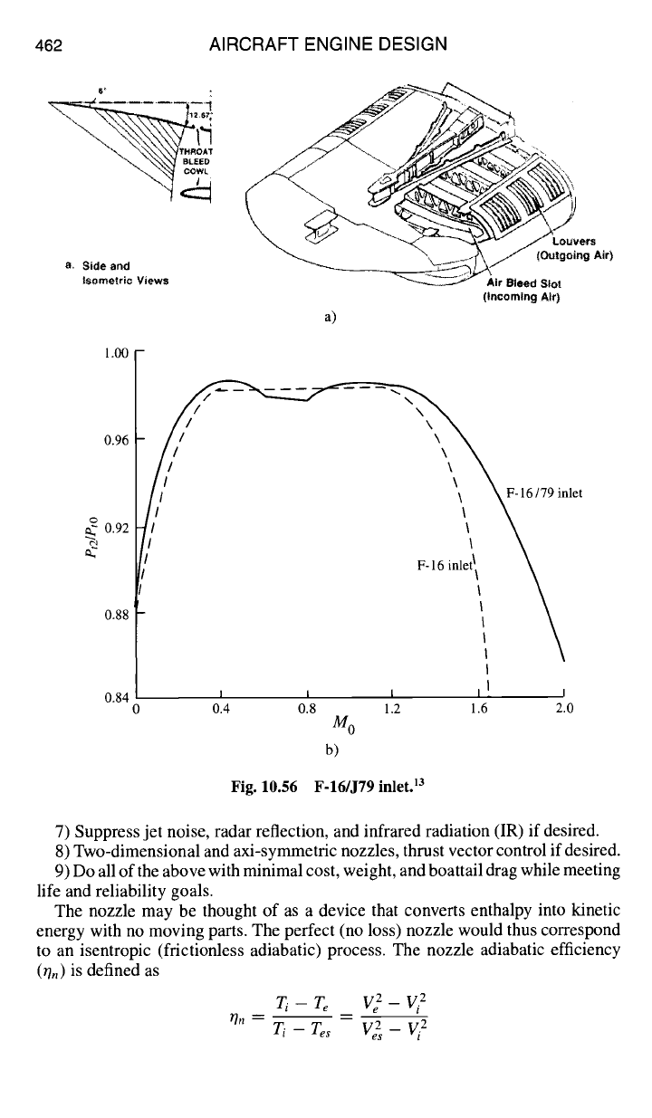
The variable, triple-ramp, external compression inlet of the F-15 aircraft is
shown in Fig. 10.57. This side view of the inlet shows the ramps as they would be
positioned when operating at the supersonic design point (ramp angles of 7 deg,
8 deg, and 8 deg for the first, second, and third ramps, respectively). The first ramp
angle is fixed and the second and third ramp angles are variable. The inlet capture
area of this inlet is variable with movement of the first ramp/top of inlet assembly
from -4 deg to 4-11 deg (this assembly is shown at 0 deg).
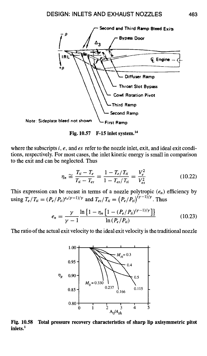
10.2.3.13 Flow separation from sharp lip inlets.
Airflow may separate
from either the inside surface or outside surface of the sharp lip present on most
supersonic inlets when operated at subsonic flight Mach numbers. Separation from
the outside surface increases inlet drag and separation from the inside surface
creates inlet flow distortion and reduces the total pressure recovery of the inlet
(see Fig. 10.58), both of which reduce the installed engine performance. Auxiliary
air inlets (also called blow-in doors) that reduce additive drag also reduce the flow
separation from the inside surface of sharp lip inlets when operated at takeoff
conditions.
10.3 Exhaust Nozzles
The purpose of the exhaust nozzle is to increase the velocity of the exhaust gas
before discharge from the nozzle and to collect and straighten the gas flow. For
large values of thrust, the kinetic energy of the exhaust gas must be high, which
implies a high exhaust velocity. The pressure ratio across the nozzle controls the
expansion process and the maximum uninstalled thrust for a given engine is ob-
tained when the exit pressure
(Pe)
equals the ambient pressure (P0).
The functions of the nozzle may be summarized by the following list:
1) Accelerate the flow to a high velocity with minimum total pressure loss.
2) Match exit and atmospheric pressure as closely as desired.
3) Permit afterburner operation without affecting main engine operation--
requires variable throat area nozzle.
4) Allow for cooling of walls if necessary.
5) Mix core and bypass streams of turbofan if necessary.
6) Allow for thrust reversing if desired.
462 AIRCRAFT ENGINE DESIGN
~ ~ " LO
vers
r
Isometric Views Air Bleed
SlOt
(incoming AIr)
a)
1.00
0.96
c~
.~ 0.92
0.88 1
0.84
m_--
6/79 inlet
/I
F-16 inlel i
i \
I
I I I I I, ,
0 0.4 0.8 1.2 1.6 2.0
M o
b)
Fig. 10.56 F-16/J79 inlet, la
7) Suppress jet noise, radar reflection, and infrared radiation (IR) if desired.
8) Two-dimensional and axi-symmetfic nozzles, thrust vector control if desired.
9) Do all of the above with minimal cost, weight, and boattail drag while meeting
life and reliability goals.
The nozzle may be thought of as a device that converts enthalpy into kinetic
energy with no moving parts. The perfect (no loss) nozzle would thus correspond
to an isentropic (frictionless adiabatic) process. The nozzle adiabatic efficiency
(r/n) is defined as
Ti -Te V 2- Vi 2
~n -- -- --
Ti -res V 2 - Vi 2
DESIGN: INLETS AND EXHAUST NOZZLES 463
_
P f Second lind Third Ramp Bleed Exits
f f',o-o=,
~~ ~ Diffuser Ramp
~-- Thr~t Slot Bypl~s
~
L Cowl Rotation
Pivot
~ ~Third Ramp
Note:
$ideplate bleed not ,hown ~ Fi nSet CR°:d: amp
Fig. 10.57 F-15 inlet system.
TM
where the subscripts i, e, and
es
refer to the nozzle inlet, exit, and ideal exit condi-
tions, respectively. For most cases, the inlet kinetic energy is small in comparison
to the exit and can be neglected. Thus
Tti - re
1 - Te/ Tti Ve 2
r/,, _ -- -- (10.22)
Tti- Tes
1
-- Tes/ Tti Ve2s
This expression can be recast in terms of a nozzle polytropic (en) efficiency by
using
Te/ Ta = ( Pe/ Pti) e"(y-1)/× and Tes/ Tti = ( Pd Pti) (v-l)~×.
Thus
y ln{1-rl,[1-(Pe/Pti)(×-l)/r]}
en = --
(10.23)
y - 1 In
(Pe/Pti)
The ratio of the actual exit velocity to the ideal exit velocity is the traditional nozzle
oR
1.00 I I I I
~
th =
0.3
0.95 - 0.4
0.90 -
M0=0'3!~0'5
0.85- 0.237 ~ 0.115
0.166
0.80
o
i
Ao/Ath
Fig. 10.58 Total pressure recovery characteristics of sharp lip axisymmetric pitot
inlets.:
464 AIRCRAFT ENGINE DESIGN
en
1.00
0.95
0.90
0.85
0.80
''''1
f
I''''1''''1'
C v
= 0.98
Cv
= 0.95
, , , , I , , ~ , I i , , L
[
.... I
....
0.0 0.1 0.2 0.3 0.4 0.5
Expansion Ratio -
P,,/P,
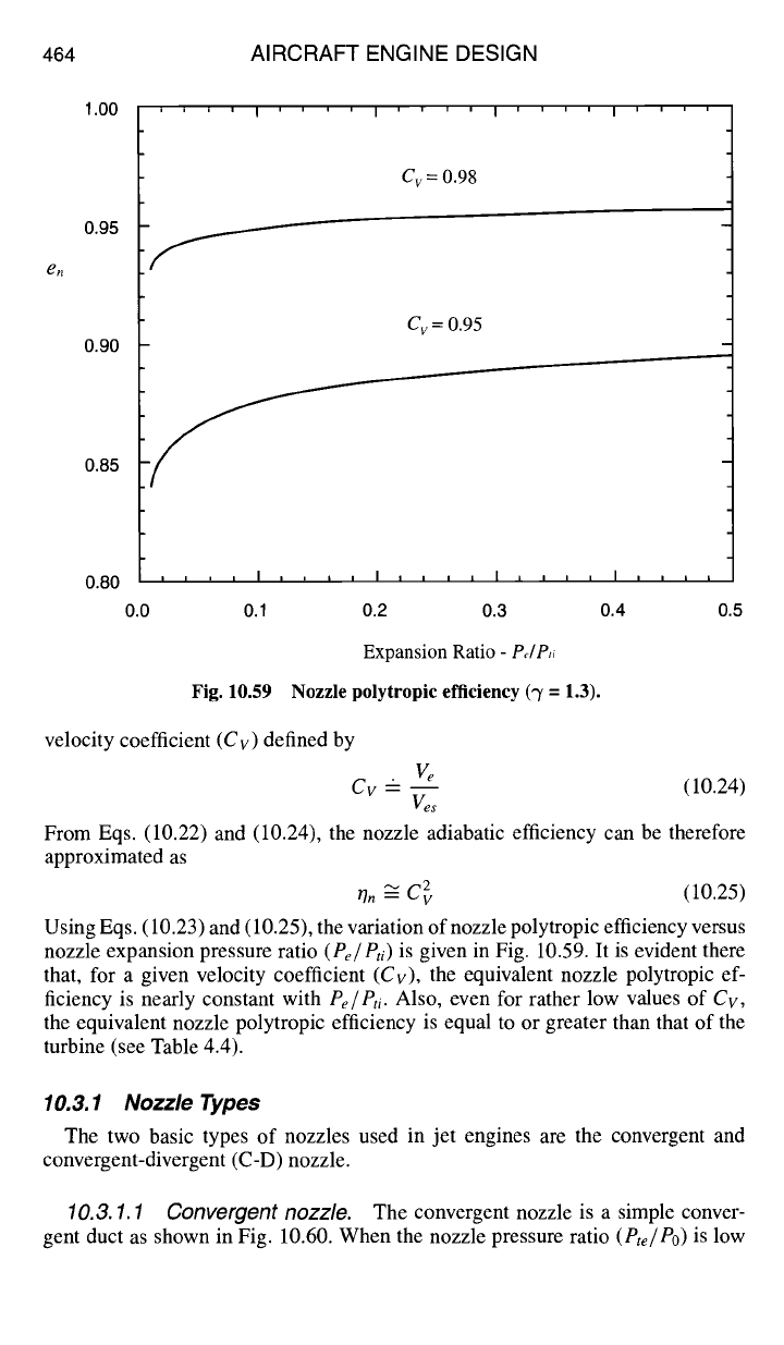
Fig. 10.59 Nozzle polytropic efficiency ('T = 1.3).
velocity coefficient
(Cv)
defined by
ve
Cv -- --
(10.24)
½s
From Eqs. (10.22) and (10.24), the nozzle adiabatic efficiency can be therefore
approximated as
~Tn -~ C 2 (10.25)
Using Eqs. (10.23) and (10.25), the variation of nozzle polytropic efficiency versus
nozzle expansion pressure ratio
(Pe/Pti)
is given in Fig. 10.59. It is evident there
that, for a given velocity coefficient
(Cv),
the equivalent nozzle polytropic ef-
ficiency is nearly constant with
Pe/Pti.
Also, even for rather low values of
Cv,
the equivalent nozzle polytropic efficiency is equal to or greater than that of the
turbine (see Table 4.4).
10.3.1 Nozzle Types
The two basic types of nozzles used in jet engines are the convergent and
convergent-divergent (C-D) nozzle.
10.3. 1.1 Convergent nozzle.
The convergent nozzle is a simple conver-
gent duct as shown in Fig. 10.60. When the nozzle pressure ratio
(Pte/Po)
is low
DESIGN: INLETS AND EXHAUST NOZZLES 465
Nozzle entrance Nozzle throat
Fig. 10.60 Convergent exhaust nozzle.
(less than about 4), the convergent nozzle is used. The convergent nozzle has
generally been used in engines for subsonic aircraft.
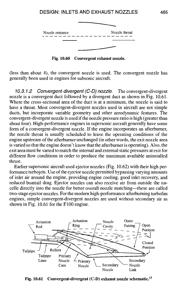
10.3. 1.2 Convergent-divergent
(C-D)
nozzle.
The convergent-divergent
nozzle is a convergent duct followed by a divergent duct as shown in Fig. 10.61.
Where the cross-sectional area of the duct is at a minimum, the nozzle is said to
have a throat. Most convergent-divergent nozzles used in aircraft are not simple
ducts, but incorporate variable geometry and other aerodynamic features. The
convergent-divergent nozzle is used if the nozzle pressure ratio is high (greater than
about four). High-performance engines in supersonic aircraft generally have some
form of a convergent-divergent nozzle. If the engine incorporates an afterburner,
the nozzle throat is usually scheduled to leave the operating conditions of the
engine upstream of the afterburner unchanged (in other words, the exit nozzle area
is varied so that the engine doesn't know that the afterburner is operating). Also, the
exit area must be varied to match the internal and external static pressures at exit for
different flow conditions in order to produce the maximum available uninstalled
thrust.
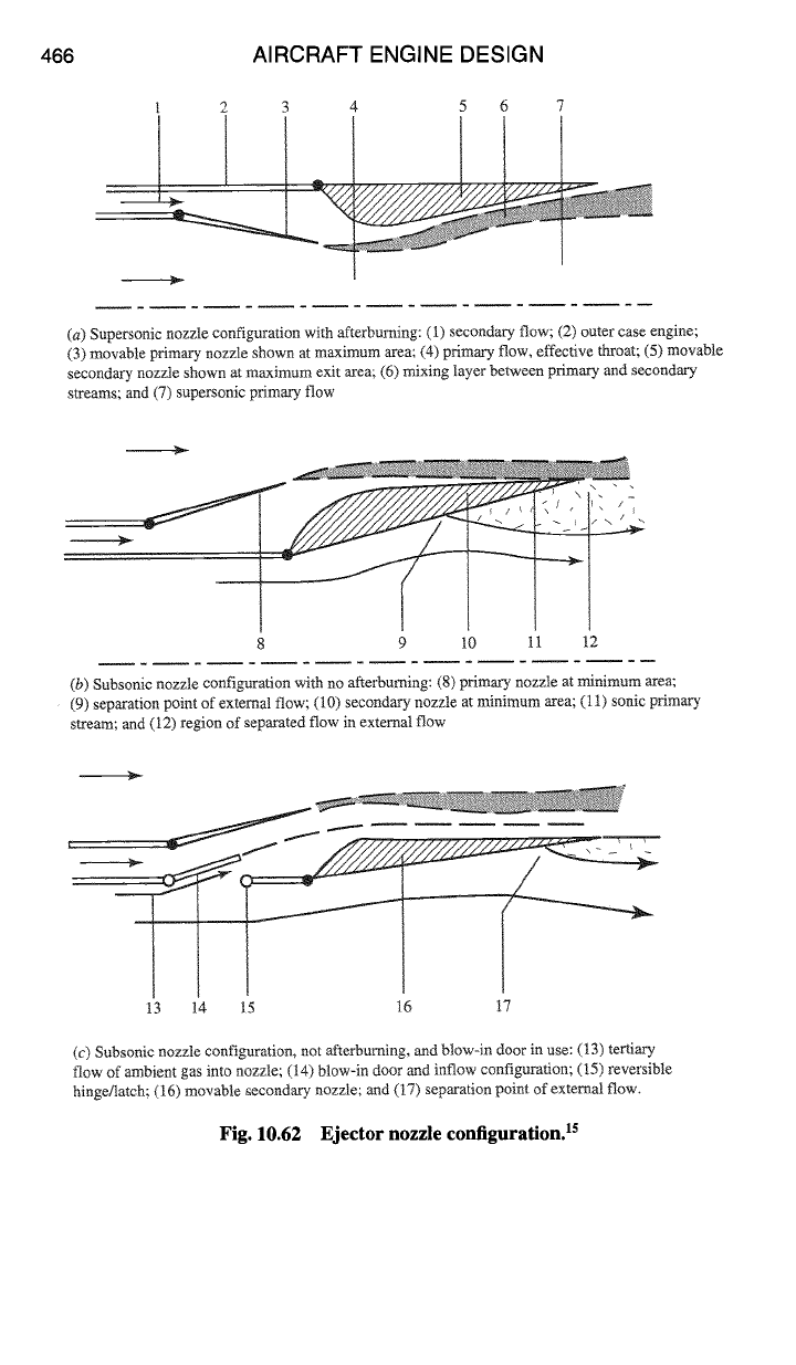
Earlier supersonic aircraft used ejector nozzles (Fig. 10.62) with their high per-
formance turbojets. Use of the ejector nozzle permitted bypassing varying amounts
of inlet air around the engine, providing engine cooling, good inlet recovery, and
reduced boattail drag. Ejector nozzles can also receive air from outside the na-
celle directly into the nozzle for better overall nozzle matching--these are called
two-stage ejector nozzles. For the modem high-performance afterbuming turbofan
engines, simple convergent-divergent nozzles are used without secondary air as
shown in Fig. 10.61 for the F100 engine.
Actuation Actuation Nozzle Outer
~
Rod /- Ring /-- Cavity Fairing Z Open
~----
__ /-- -- -- _ ~ [ Position
~ 5 I Roll-ers~~-~ - ~~ Position
Tailpipe ~
/ Roll2s
T.~lePripe ~mg Lrima'~ ~ "~'x- Second~
Cam Nozzle ~_ Secondary Nozzle
Nozzle Link
Fig. 10.61 Convergent-divergent (C-D) exhaust nozzle schematic, is
466 AIRCRAFT ENGINE DESIGN
2 3
4 5 6
(a) Supersonic nozzle configuration with afterburning: (1) secondary flow; (2) outer case engine;
(3) movable primary nozzle shown at maximum area; (4) primary flow, effective throat; (5) movable
secondary nozzle shown at maximum exit area; (6) mixing layer between primary and secondary
streams; and (7) supersonic primary flow
IP
/-
8 9
10 11 12
(b) Subsonic nozzle configuration with no afterburning: (8) primary nozzle at minimum area;
(9) separation point of external flow; (10) secondary nozzle at minimum area; (11) sonic primary
stream; and (12) region of separated flow in external flow
ID
13 14 15 16 17
(c) Subsonic nozzle configuration, not afterburning, and blow-in door in use: (13) tertiary
flow of ambient gas into nozzle; (14) blow-in door and inflow configuration; (15) reversible
hinge/latch; (16) movable secondary nozzle; and (17) separation point of external flow.
Fig. 10.62 Ejector nozzle configuration: 5