Mattingly J.D., Heiser W.H., Pratt D.T. Aircraft Engine Design
Подождите немного. Документ загружается.

386 AIRCRAFT ENGINE DESIGN
enter the afterburner at stations 6 and 16, respectively, in Fig. 9.2a. In addition,
the afterburner fuel flow rate that enters between stations 6A and 6.1 is also spec-
ified. When using the AEDsys software for preliminary design, these values are
displayed on the Engine Station Test Results sheet for the particular operating
point chosen for design (see Table 7.E5). The required thermodynamic state of
the combustion product gases exiting the afterburner at station 7 is also fixed. The
radial and axial location of all components of the afterburner assembly in the en-
gine framework will be determined by matching the layout of the fan, turbine, and
variable area nozzles from their respective preliminary designs.
Although the afterburner fuel flow rate and Engine Station Test Results values
listed for stations 6, 16, and 6A are fixed requirements, those values listed for
station 7 are just "first cut" or "bogey" values, which may have to be adjusted in
order to optimize performance. The Engine Station Test Results does not list any
properties whatever for station 6.1. However, a value of total pressure loss from
station 6A to station 7 is obtainable from the Engine Station Test Results sheet,
and this should be regarded as a design target value. This design quantity can be
represented as
Pt7 et6.1 Pt7
Yr6a_ 7 ~'
.....
]TAB D T(AB
(9.121)
Pt6a Pt6a Pt6.1
which is the product of the total pressure ratios across the afterburner diffuser
(stations 6A to 6.1) and the afterburner (stations 6.1 to 7).
9.3.2 Afterburner
Components
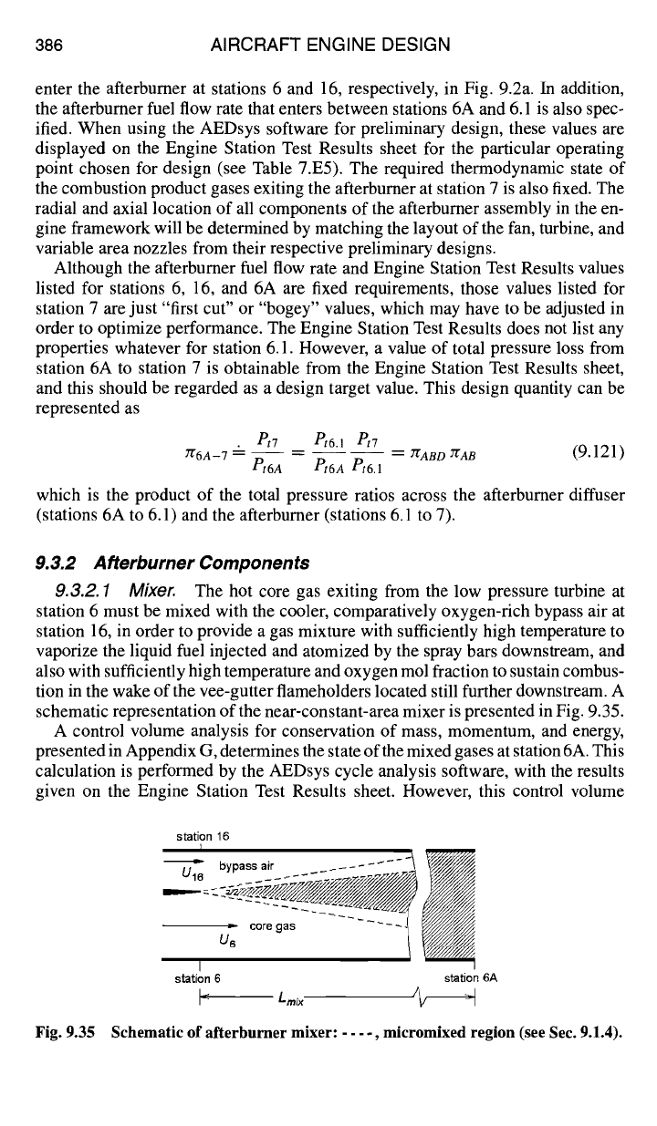
9.3.2.1 Mixer. The hot core gas exiting from the low pressure turbine at
station 6 must be mixed with the cooler, comparatively oxygen-rich bypass air at
station 16, in order to provide a gas mixture with sufficiently high temperature to
vaporize the liquid fuel injected and atomized by the spray bars downstream, and
also with sufficiently high temperature and oxygen mol fraction to sustain combus-
tion in the wake of the vee-gutter flameholders located still further downstream. A
schematic representation of the near-constant-area mixer is presented in Fig. 9.35.
A control volume analysis for conservation of mass, momentum, and energy,
presented in Appendix G, determines the state of the mixed gases at station 6A. This
calculation is performed by the AEDsys cycle analysis software, with the results
given on the Engine Station Test Results sheet. However, this control volume
station 16
I
U " bypass air ........ -~
, ~ ~oregas
--1
I
station 6
station 6A
L mix
/~
Fig. 9.35 Schematic of afterburner mixer: .... , micromixed region (see Sec. 9.1.4).
DESIGN: COMBUSTION SYSTEMS 387
analysis is based on the assumption that mixing is complete at exit and does not
address the question of how long the mixer must be to accomplish this mixing.
The length required for complete mixing of the core gas and bypass airstreams,
as denoted by
Lmix
in Fig. 9.35, can be estimated by using the shear/mixing layer
equations [Eqs. (9.52-9.60) from Sec. 9.1.4 (see also Figs. 9.18 and 9.19)]. How-
ever, as Fig. 9.35 suggests, the distance required may be excessively long, as one
stream may "mix out" while the other stream still contains unmixed gas. One way
to reduce the length required to mix out is to reduce the annular height of both
passages at mixer inlet, which reduces the initial scale of segregation of the two
mixant streams. 13 This can be done by constant-area ducting (that is, by keeping
the product of cross-sectional radial height H and mean radius
rm
constant as
r m
is increased) both streams to the greatest permissible outer radius prior to mix-
ing. Some other ways are to l) increase the velocity ratio of the two streams [see
Eqs. (9.52-9.54)], 2) purposely imbalance or "un-match" the static pressures in the
two streams so that the higher-pressure stream is pushed laterally into the lower-
pressure stream, and 3) replace the flat-edge splitter plate illustrated in Fig. 9.35
with a "fluted" plate, which can be visualized as a flat plate trailing edge that is
smoothly crimped laterally, similar to hand-crimping the top and bottom layers of
a pie crust. The fluted splitter plate induces vertical velocity components, spatially
alternating upward and downward from both mixant streams, which reduces the
scale of segregation between the two mixants to the pitch of the corrugations in
the fluted splitter plate. Of course, all of the suggested ways to shorten
Lmix
cause
further increases in total pressure loss.
In any case the rational design of the mixer is far too complicated for treatment
at our level of description, 13 and so the properties at stations 6, 16, and 6A listed
on the Engine Station Test Results sheet will simply be taken as given for prelim-
inary design purposes, and the required length can only be guessed or based on
observation of similar designs.
An alternative approach is to not mix the two streams at all. By keeping the two
streams separate until just upstream of the hot section, temperature modulation
for the afterburner can be achieved by having two separately fueled afterburner
systems, one located in the core stream and the other in the unmixed bypass
fan airstream. Stage 1 would be the inner, core stream afterburner, and after the
first stage is lit off, the separately fueled, outer, bypass fan airstream afterburner
could be ignited for stage 2. This in turn leads to flameholding difficulties in both
streams because although the hot core stream is oxygen poor, compared to the
bypass stream, the oxygen-rich bypass stream (air) is cold in comparison with the
core stream.
9.3.2.2 Diffuser. The flow entering the afterburner at station 6A (Fig. 9.2a)
must be slowed to a Mach number that provides a balance between total pressure
loss and afterburner cross-sectional area. The minimum Mach number entering
the combustion zone of the afterburner at station 6.1 is usually fixed by a require-
ment that the diameter of the afterburner section not exceed that of the engine
components located upstream, specifically the fan casing, for case of installation
and removal. A short diffuser length is desired, of course without producing flow
separation, in order to reduce engine weight and length. In augmented turbofan
engines, the diffuser may be combined with a mixer so that a mixed stream enters
388 AIRCRAFT ENGINE DESIGN
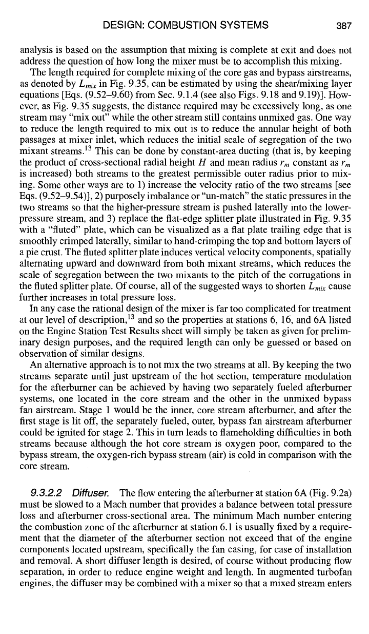
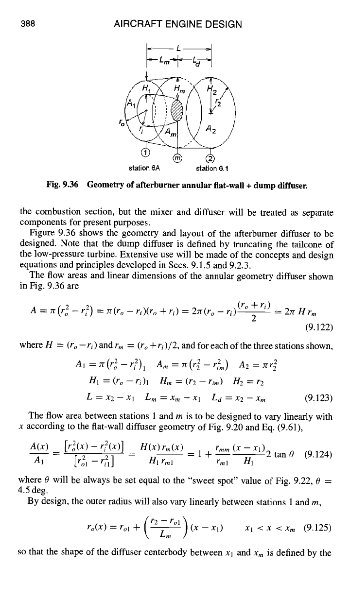
Fig. 9.36
ro
/
station 6A station 6.1
Geometry of afterburner annular flat-wall + dump diffuser.
the combustion section, but the mixer and diffuser will be treated as separate
components for present purposes.
Figure 9.36 shows the geometry and layout of the afterburner diffuser to be
designed. Note that the dump diffuser is defined by truncating the tailcone of
the low-pressure turbine. Extensive use will be made of the concepts and design
equations and principles developed in Secs. 9.1.5 and 9.2.3.
The flow areas and linear dimensions of the annular geometry diffuser shown
in Fig. 9.36 are
A = zr(r2o - r2i) = zr(ro
- ri)(ro
-t- ri)
=
2rr(ro - ri) (ro + ri)
_
2zr H
r m
2
(9.122)
where H =
(ro - ri)
and
rm
= (ro +
ri
)/2,
and for each of the three stations shown,
Al=yr(r 2-1"2)1
Am = Tr(r 2 - r2m) A2 = Jrr~
H1 = (ro - ri)l nm=
(r2 -
rim) H2 -= r2
L = x2 - xl Lm = Xm - Xl La = x2 - xm
(9.123)
The flow area between stations 1 and m is to be designed to vary linearly with
x according to the flat-wall diffuser geometry of Fig. 9.20 and Eq. (9.61),
A(x) _
[rZ(x) - rZ(x)] _
n(x)rm(x) _ 1 -t- rmm (X
--Xl)
2 tan 0 (9.124)
AI
[ro21 -- rT1]
Hlrml
rml
HI
where 0 will be always be set equal to the "sweet spot" value of Fig. 9.22, 0 =
4.5 deg.
By design, the outer radius will also vary linearly between stations 1 and m,
ro(X) = rol + (r2 -- rol ~ (x - x,) Xl < x < Xm
(9.125)
~LmJ
so that the shape of the diffuser centerbody between xl and
x m
is defined by the
DESIGN: COMBUSTION SYSTEMS 389
variation of inner radius of the flow area with x between i and m, from Eq. (9.124),
as
ri(x) ~r2(x)Zl (l+rmm( -Xl)2 )
.... tan 4.5deg Xl <x <xm (9.126)
7r rm 1 H1
Note that the axial variation of the inner radius
ri(x)
is
quasi-linear
in x, not
quadratic, because it varies as the square root of a quadratic function.
If the overall area ratio
AR= A2/A 1
is greater than four, the length of the diffuser
centerbody will be the "sweet spot" value
Lm/H1
= 20.
IfAR
is less than four,
then from Eqs. (9.103) and (9.124)
Lm rmlH1
([A~-I] 1)where [A-~I ]
= -- = rIDmAR
rmm
2 tan 4.5 deg
opt opt
(9.127)
Finally, the diffusion efficiency of the combined diffuser is given by Eq. (9.102),
~IDmAR2(1 - [al/am] 2) + 2(AR[A1/Am] -
1)
(9.128)
riD =
(AR 2 -
1)
where, as before,
AR
denotes the overall area ratio
AR = A2/A1.
009 ° from
Eq. (9.68) should be used for 0ore in Eq. (9.128), the total pressure loss can be
calculated from Eq. (9.67), and the tailpipe length
Ld
of the combined diffuser
will be
Ld = H2 - Hm.
9.3.2.3 Fuel injection, atomization, and vaporization.
This subject area
is best summarized by Zukoski 3 and is quoted here:
The goal of the fuel injection system is to produce a specified distribution
of fuel vapor in the gas stream entering the afterburner. In most engines, fuel is
introduced in a staged manner so that heat addition rate can be increased gradually
from zero to the desired value. Because ignition, flame stabilization, and flame
spreading are easiest to achieve when the fuel-air ratio is close to the stoichiometric
value, staging is usually produced by adding fuel to successive annular stream
tubes so that the mixture ratio in each tube is nearly stoichiometric. Each stream
tube has its own set of fuel injectors and control system which can be activated
independently.
The most remarkable fact concerning the fuel system for afterburners is
their simplicity. In many engine systems, fuel is supplied to a circular tube which
lies with its axis perpendicular to the gas stream. Fuel is injected into the gas
through small diameter holes located in the sides of the tubes such that the liquid
jet enters the gas stream in a direction perpendicular to the undisturbed flow
direction. The liquid jet penetrates some distance into the gas stream before its
momentum is dissipated. During this penetration process, the air stream tears the
jet apart and produces droplets with diameters of micron size. Heat transfer from
the hot gas stream then vaporizes the droplets.
Given the wide range of values of mass flows of fuel required, it is remark-
able that reasonably thorough mixing of the fuel with the air can be achieved with
390 AIRCRAFT ENGINE DESIGN
this simple injection system. In some recent engines efforts are being made to use
simple variable area injection ports which may possibly give better preparation
of the fuel-air mixture.
The whole area of fuel penetration, atomization, and vaporization is not
well understood from first principles and one of the time consuming parts of an
afterburner development program is to determine the optimum distribution of
locations for injector tubes, injector ports, and port diameters.
A good source of information concerning fuel spray injection, atomization, and
vaporization is given by Chigier. 3°
9. 3.2.4 Ignition. Ignition of the fuel-air mixture in the afterburner is usually
accomplished using a spark or arc igniter or a pilot burner. Once initiated in the
primary stream tube, combustion continues in the wake of the fame stabilizer, and
the process will spread to the rest of the flame stabilizers.
The spark or arc igniter uses a high-energy electric arc to initiate combustion of
the primary stream tube. The igniter is usually placed in the wake of a sheltered
flame stabilizer having its own fuel supply. A stable flame results, and combustion
is initiated behind other flame stabilizers by the mechanism just mentioned.
The pilot burner consists of a pilot zone where a small portion of the inlet
air (usually 10% or less) is burned to stoichiometric temperatures in an enclosed
protected region. The hot gases generated by the pilot are used as an ignition and
stabilizing source for the main fuel injection system.
Afterburning for some turbofan engines is accomplished by adding fuel first
to the core flow near the interface between the core and fan streams, then to the
fan stream, and finally to the rest of the core flow. Afterburning in the fan stream
produces the largest performance gain because of the low temperature of this
stream. However, the fan stream's low temperature makes fuel vaporization and
afterburning very difficult. By adding fuel first to the core flow near its interface
with the fan stream, the resulting afterburning stream can act as a pilot for the
combustion process in the fan stream.
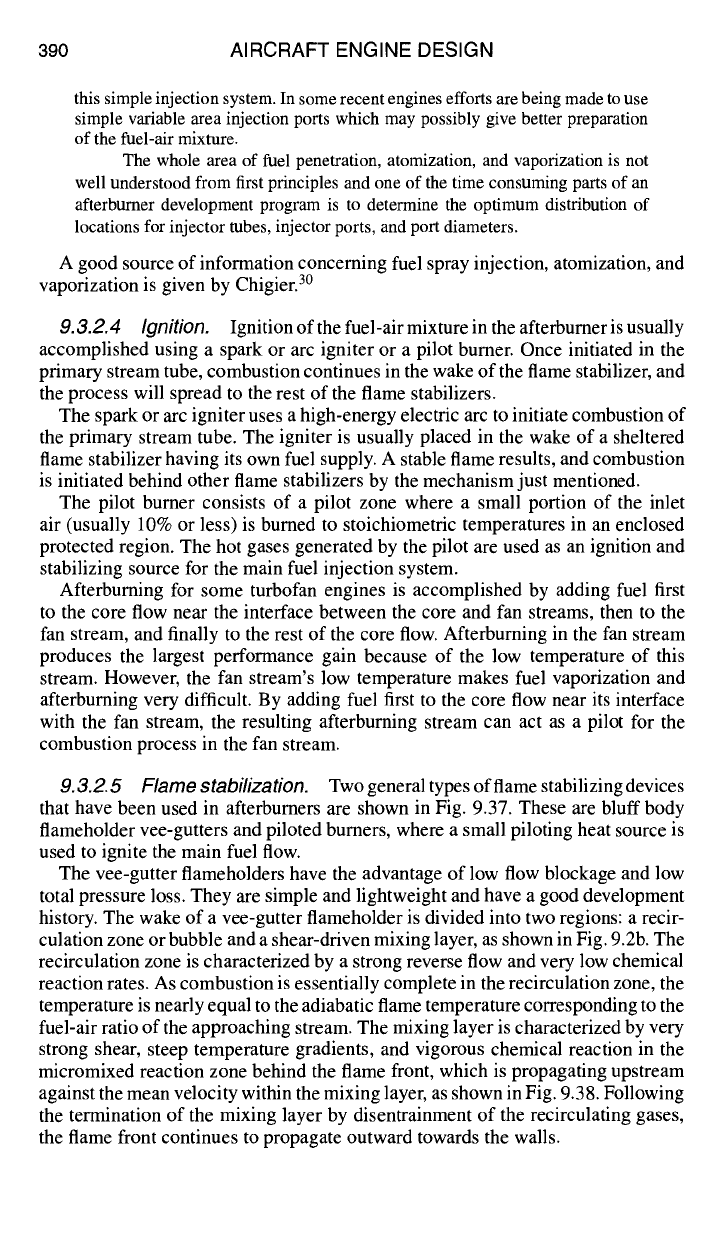
9.3.2.5 Flame stabilization. Twogeneraltypesofflamestabilizingdevices
that have been used in afterburners are shown in Fig. 9.37. These are bluff body
flameholder vee-gutters and piloted burners, where a small piloting heat source is
used to ignite the main fuel flow.
The vee-gutter flameholders have the advantage of low flow blockage and low
total pressure loss. They are simple and lightweight and have a good development
history. The wake of a vee-gutter flameholder is divided into two regions: a recir-
culation zone or bubble and a shear-driven mixing layer, as shown in Fig. 9.2b. The
recirculation zone is characterized by a strong reverse flow and very low chemical
reaction rates. As combustion is essentially complete in the recirculation zone, the
temperature is nearly equal to the adiabatic flame temperature corresponding to the
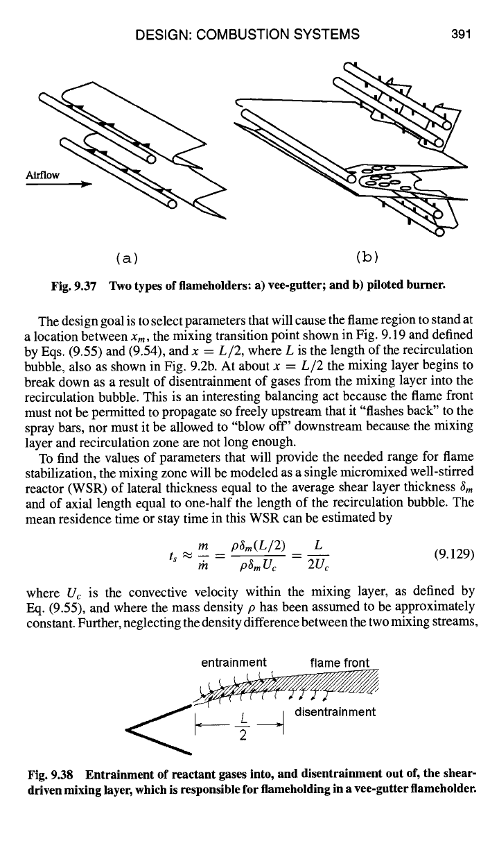
fuel-air ratio of the approaching stream. The mixing layer is characterized by very
strong shear, steep temperature gradients, and vigorous chemical reaction in the
micromixed reaction zone behind the flame front, which is propagating upstream
against the mean velocity within the mixing layer, as shown in Fig. 9.38. Following
the termination of the mixing layer by disentrainment of the recirculating gases,
the flame front continues to propagate outward towards the walls.
Airflow
DESIGN: COMBUSTION SYSTEMS
391
(a) (b)
Fig. 9.37 Two types of flameholders: a) vee-gutter; and b) piloted burner.
The design goal is to select parameters that will cause the flame region to stand at
a location between
Xm,
the mixing transition point shown in Fig. 9.19 and defined
by Eqs. (9.55) and (9.54), and x =
L/2,
where L is the length of the recirculation
bubble, also as shown in Fig. 9.2b. At about x =
L/2
the mixing layer begins to
break down as a result of disentrainment of gases from the mixing layer into the
recirculation bubble. This is an interesting balancing act because the flame front
must not be permitted to propagate so freely upstream that it "flashes back" to the
spray bars, nor must it be allowed to "blow off' downstream because the mixing
layer and recirculation zone are not long enough.
To find the values of parameters that will provide the needed range for flame
stabilization, the mixing zone will be modeled as a single micromixed well-stirred
reactor (WSR) of lateral thickness equal to the average shear layer thickness
~m
and of axial length equal to one-half the length of the recirculation bubble. The
mean residence time or stay time in this WSR can be estimated by
m pSm(L/2) L
ts "~ -- (9.129)
r'n p~m Uc 2Uc
where Uc is the convective velocity within the mixing layer, as defined by
Eq. (9.55), and where the mass density p has been assumed to be approximately
constant. Further, neglecting the density difference between the two mixing streams,
entrainment flame front
~
., ~_ ~. disentrainment
Fig. 9.38 Entrainment of reactant gases into, and disentrainment out of, the shear-
driven mixing layer, which is responsible for flameholding in a vee-gutter flameholder.
392 AIRCRAFT ENGINE DESIGN
then
Uc "" U2/2,
and Eq. (9.129) may be rewritten as
(L/2) L
t~ ~ -- (9.130)
(U2/2) U2
The requirement for the flame front to stabilize is therefore that the residence
time or stay time
ts
of the gases flowing through the mixing layer must be greater
than, or equal to, the WSR residence time at blowout
tBo
as defined and discussed
in Sec. 9.1.3.
Because ts >
tso
in the mixing layer is required, then the design requirement
for flame stabilization can be stated as
L
ts .~ -- > tBo
required (9.131)
U2
Substituting the estimate L --- 4W (Ref. 3) into Eq. (9.131), the stabilization
requirement becomes
4W
ts ~ -- > tBo
required (9.132)
U2
Because both U2 and W depend on the blockage B, approach velocity U1, and
vee-gutter half-angle 0, the requirement Eq. (9.132) must be rewritten in terms of
the controllable design parameters H, D, 0, and U1. Conservation of mass requires
that
U1H=Uz(H-W),
so thatUz=U1 ~ - (1-W/H) (9.133)
which enables Eq. (9.132) to be rewritten as
H4W( W)
ts ~ ~l -H 1 - > tBo
required (9.134)
By inspection of Eq. (9.134), it can be seen that for any given values of channel
height H and approach velocity UI, the residence time in the mixing layer is
maximized when
W/H
= 1/2, so that for optimal flameholding
-- > tso
required, when = 0.5 (9.135)
Ui
Note, however, that the optimum is fairly flat. For example, if
W/H
= 0.4
is substituted into Eq. (9.134) instead of the optimal
W/H
= 0.5, then the re-
quired ratio
H~ U1
is increased by only 4%, so that variations in practice can be
expected.
The WSR blowout residence time
tso
must be obtained either from experiment
or from chemical-kinetic WSR modeling, for example, from the AEDsys soft-
ware program KINETX. Required inputs to KINETX for calculating
t~o
are the
pressure, temperature, and composition of the approach gas stream and the ratio
of afterburner fuel flow rate to main gas stream flow rate. All of these parameters
except the gas composition are available from the Engine Station Test Results
DESIGN: COMBUSTION SYSTEMS 393
sheet. The composition of the main gas stream can be obtained from the AEDsys
program EQL.
With U1 given from the Engine Station Test Results sheet,
fro
determined from
the AEDsys program KINETX, and the minimum H determined from Eq. (9.134)
for a single vee-gutter, design choices still have to be made for the vee-gutter
lateral dimension D and half-angle 0, and how many rows (rings) of vee-gutters
and associated spray bars will be required.
Equation (9.87) gives
W/H
as a function of the blockage B =
D/H
and half-
angle 0:
W
B + (1 - ~)~/B sin(0/2) (9.136)
H
For any value of
W/H, B
and 0 are related by Eq. (9.136), but neither value is
specified. Because a half-angle of 0 = 15 deg has been widely utilized for vee-
gutter flameholders, that value will be used here. For 0 = 15 deg, and over the
useful range 0.3 <
W/H
< 0.5, Eqs. (9.87) and (9.136) can be represented to
good approximation by
B~ 1.034 -0.1 for 0=15deg, 0.3 < H <0"5 (9.137)
With the optimal
W/H
= 0.5 as input, Eq. (9.137) gives the corresponding value
of blockage B = 0.417, and the gutter lateral width D =
BH
= 0.417H. The
corresponding vee-gutter drag coefficient
CD
= 2.4 is obtained from Eq. (9.84).
These values are typical of currently operational afterburners.
However, for
W/H
= 0.4, Eq. (9.137) gives B = 0.314, and Eq. (9.84) gives
the corresponding
Co
= 1.4. From Eq. (9.85) it can be seen that reducing the
design value of
W/H
from 0.5 to 0.4 reduces the "dry" total pressure loss coef-
ficient from 1.0 to 0.444. This reduction of dry total pressure loss by 55%, at a
cost of only 4% reduction in flameholding stability, is significant and should be
considered during design of the afterburner.
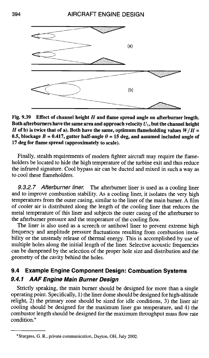
9.3.2.6 Flame spread and afterburner length.
Figure 9.39 illustrates
how the channel height H and flame spread angle determine the length of the
afterburner between stations 6.1 and 7 required for the flame front to consume all
of the reactant gases. Regrettably, there does not appear to be a reliable method
to determine the flame spread angle based on first principles, 3 and so a standard
design value of 17 deg total included angle will be assumed.
Assuming that afterburner a) of Fig. 9.39 has a channel height H that is equal
to or slightly greater than the minimum value required by Eq. (9.135), the
single-gutter afterburner b) has an unnecessarily wide stability margin for flame-
holding, and the twice-as-long flame spreading region results in a much longer
afterburner. Why not make the afterburner even shorter by further reducing the
channel height, so that there would be three or four rows (rings) of flameholders?
Because the vee-gutters would then be too small to stabilize the flame!
In summary, two design guidelines have been established for optimizing both
afterburner flameholding and flame spread: 1) H should be as small as possible in
order to minimize the length of the afterburner (flame spread), and 2) U1 should be
small as possible to maximize residence time in the mixing layer (flameholding.)
394 AIRCRAFT ENGINE DESIGN
(a)
J
••
(b)
Fig. 9.39 Effect of channel height H and flame spread angle on afterburner length.
Both afterburners have the same area and approach velocity Ul, but the channel height
H of b) is twice that of a). Both have the same, optimum flameholding values
W/H =
0.5, blockage B = 0.417, gutter half-angle 0 = 15 deg, and assumed included angle of
17 deg for flame spread (approximately to scale).
Finally, stealth requirements of modern fighter aircraft may require the flame-
holders be located to hide the high temperature of the turbine exit and thus reduce
the infrared signature. Cool bypass air can be ducted and mixed in such a way as
to cool these flameholders.
9.3.2. 7 Afterburner liner. The afterburner liner is used as a cooling liner
and to improve combustion stability. As a cooling liner, it isolates the very high
temperatures from the outer casing, similar to the liner of the main burner. A film
of cooler air is distributed along the length of the cooling liner that reduces the
metal temperature of this liner and subjects the outer casing of the afterburner to
the afterburner pressure and the temperature of the cooling flow.
The liner is also used as a screech or antihowl liner to prevent extreme high
frequency and amplitude pressure fluctuations resulting from combustion insta-
bility or the unsteady release of thermal energy. This is accomplished by use of
multiple holes along the initial length of the liner. Selective acoustic frequencies
can be dampened by the selection of the proper hole size and distribution and the
geometry of the cavity behind the holes.
9.4 Example Engine Component Design: Combustion Systems
9.4.1 AAF Engine Main Burner Design
Strictly speaking, the main burner should be designed for more than a single
operating point. Specifically, 1) the liner dome should be designed for high-altitude
relight, 2) the primary zone should be sized for idle conditions, 3) the liner air
cooling should be designed for the maximum liner gas temperature, and 4) the
combustor length should be designed for the maximum throughput mass flow rate
condition.*
*Sturgess, G. R., private communication, Dayton, OH, July 2002.
DESIGN: COMBUSTION SYSTEMS 395
As pointed out in Sec. 9.1.7, design of the ignition subsystem is regarded as
too complex for inclusion in this textbook, and so design for high-altitude relight
will not be considered. Of the remaining three considerations, it can be seen from
inspection of Table 7.E4, AAF Engine Main Burner Operation, that the maximum
dynamic pressure condition (sea level, flight Mach number M0 = 1.2) establishes
both the maximum gas temperature and maximum throughput condition. In the
interest of clarity and simplicity, therefore, that condition will be chosen as the
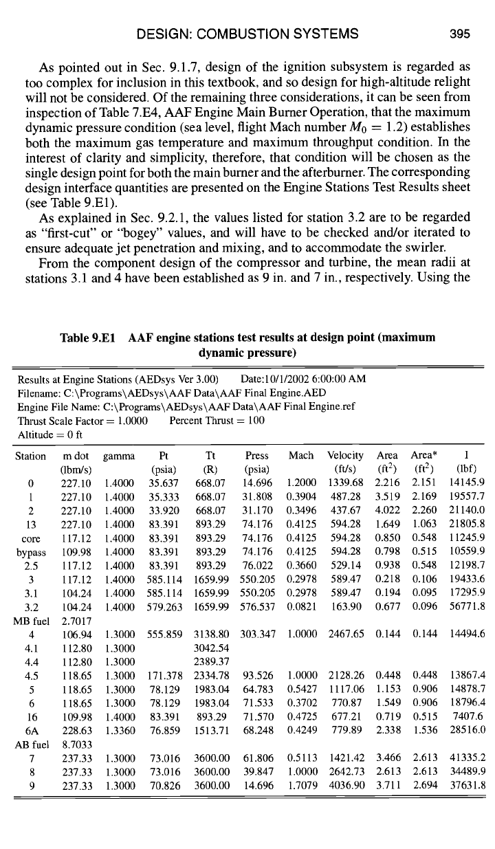
single design point for both the main burner and the afterburner. The corresponding
design interface quantities are presented on the Engine Stations Test Results sheet
(see Table 9.El).
As explained in Sec. 9.2.1, the values listed for station 3.2 are to be regarded
as "first-cut" or "bogey" values, and will have to be checked and/or iterated to
ensure adequate jet penetration and mixing, and to accommodate the swirler.
From the component design of the compressor and turbine, the mean radii at
stations 3.1 and 4 have been established as 9 in. and 7 in., respectively. Using the
Table 9.El AAF engine stations test results at design point (maximum
dynamic pressure)
Results at Engine Stations (AEDsys Ver 3.00) Date: 10/1/2002 6:00:00 AM
Filename: C:\Programs\AEDsys\AAF Data\AAF Final Engine.AED
Engine File Name: C:\Programs\AEDsys\AAF Data\AAF Final Engine.ref
Thrust Scale Factor = 1.0000 Percent Thrust = 100
Altitude = 0 ft
Station m dot gamma Pt Tt Press Mach Velocity Area Area* I
(Ibm/s) (psia) (R) (psia) (ft/s) (ft 2 ) (ft 2 ) (lbf)
0 227.10 1.4000 35.637 668.07 14.696 1.2000 1339.68 2.216 2.151 14145.9
1 227.10 1.4000 35.333 668.07 31.808 0.3904 487.28 3.519 2.169 19557.7
2 227.10 1.4000 33.920 668.07 31.170 0.3496 437.67 4.022 2.260 21140.0
13 227.10 1.4000 83.391 893.29 74.176 0.4125 594.28 1.649 1.063 21805.8
core 117.12 1.4000 83.391 893.29 74.176 0.4125 594.28 0.850 0.548 11245.9
bypass 109.98 1.4000 83.391 893.29 74.176 0.4125 594.28 0.798 0.515 10559.9
2.5 117.12 1.4000 83.391 893.29 76.022 0.3660 529.14 0.938 0.548 12198.7
3 117.12 1.4000 585.114 1659.99 550.205 0.2978 589.47 0.218 0.106 19433.6
3.1 104.24 1.4000 585.114 1659.99 550.205 0.2978 589.47 0.194 0.095 17295.9
3.2 104.24 1.4000 579.263 1659.99 576.537 0.0821 163.90 0.677 0.096 56771.8
MB fuel 2.7017
4 106.94 1.3000 555.859 3138.80 303.347 1.0000 2467.65 0.144 0.144 14494.6
4.1 112.80 1.3000 3042.54
4.4 112.80 1.3000 2389.37
4.5 118.65 1.3000 171.378 2334.78 93.526 1.0000 2128.26 0.448 0.448 13867.4
5 118.65 1.3000 78.129 1983.04 64.783 0.5427 1117.06 1.153 0.906 14878.7
6 118.65 1.3000 78.129 1983.04 71.533 0.3702 770.87 1.549 0.906 18796.4
16 109.98 1.4000 83.391 893.29 71.570 0.4725 677.21 0.719 0.515 7407.6
6A 228.63 1.3360 76.859 1513.71 68.248 0.4249 779.89 2.338 1.536 28516.0
AB fuel 8.7033
7 237.33 1.3000 73.016 3600.00 61.806 0.5113 1421.42 3.466 2.613 41335.2
8 237.33 1.3000 73.016 3600.00 39.847 1.0000 2642.73 2.613 2.613 34489.9
9 237.33 1.3000 70.826 3600.00 14.696 1.7079 4036.90 3.711 2.694 37631.8