Mattingly J.D., Heiser W.H., Pratt D.T. Aircraft Engine Design
Подождите немного. Документ загружается.

406 AIRCRAFT ENGINE DESIGN
Table 9.E5 AAF engine afterburner core and bypass flow areas and radii
Stations
Station Station Station Station Station 6.1 and 7
5 (core) 6 (core) 13 (bypass) 16 (bypass) 6A (mixed) (mixed)
ro (in.) 11.0 14.6 13.4 15.7 15.7 15.7
ri (in.) 7.0 11.9 12.0 14.6 11.8 0.0
A (ft 2) 1.571 a 1.549 0.798 0.719 2.338 5.378
aArea at station 5 from low-pressure turbine design (see Sec. 8.3.4).
9.4.2.1 Mixer. As shown in Sec. 9.3.2, it is not feasible to design the mixer
from first principles. However, some calculations can be performed that illus-
trate the magnitude of the mixing problem, and some possible solutions can be
suggested. From Table 9.El, the areas, mass flow rates and thermodynamic prop-
erties of the mixer inlet flows at stations 6 and 16 are available. Substituting these
numbers into the mixing layer Eqs. (9.52-9.58), the velocity ratio r and density
ratio s for the shear/mixing layer can be calculated,
U16
677.21 P16 Tt6 1983.04
r ..... 0.8785 and s = -- ~ .... 2.220
U6 770.87 P6
Ttl6
893.29
from which the maximum possible rate of growth of the mixing layer (imbedded
in the shear layer) is
-- = C8 (0.0332) = 0.0150, for (CDmax = 0.45
x
From the geometry of Fig. 9.35 in Sec. 9.3.2,
Lm
would have to be over 12 ft,
for just the bypass stream to mix out! This is obviously not acceptable. What is
wrong, and what is to be done about it?
The problem is that in order to pressure-match the two streams prior to mixer
entry the bypass stream is slightly accelerated from station 13 to 16, while the
core stream remains at essentially constant area and velocity from station 5
to 6 (see Sec. 8.3.4.) This results in a velocity difference between the two streams
at mixer entry AU
= (U 6 - U16) =
(770.87 - 677.21) = 93.66 ft/s, which
appears to be large enough to strongly drive the shear layer. However, as can be
seen by inspection of Eq. (9.54), it is the velocity ratio, not the difference, that
determines the axial rate of growth of the shear layer, and the ratio of two large
velocities, r = 0.8785, is too close to 1.0 for the shear/mixing layer to grow at
an adequate rate. Even though a ~94 ft/s velocity difference produces a strongly
driven shear/mixing layer, the mean convective velocity of 724 ft/s convects the
developing shear/mixing layer downstream so rapidly that the axial growth rate is
small.
What is to be done about it? Noting that the component immediately downstream
of the mixer is the diffuser, it will be recalled from Secs. 9.1.5 and 9.2.3 that the
best, "sweet spot" diffuser design operates within the mild transitory stall regime,
labeled "some stall" in Figs. 9.21 and 9.22. The flow in this regime periodically
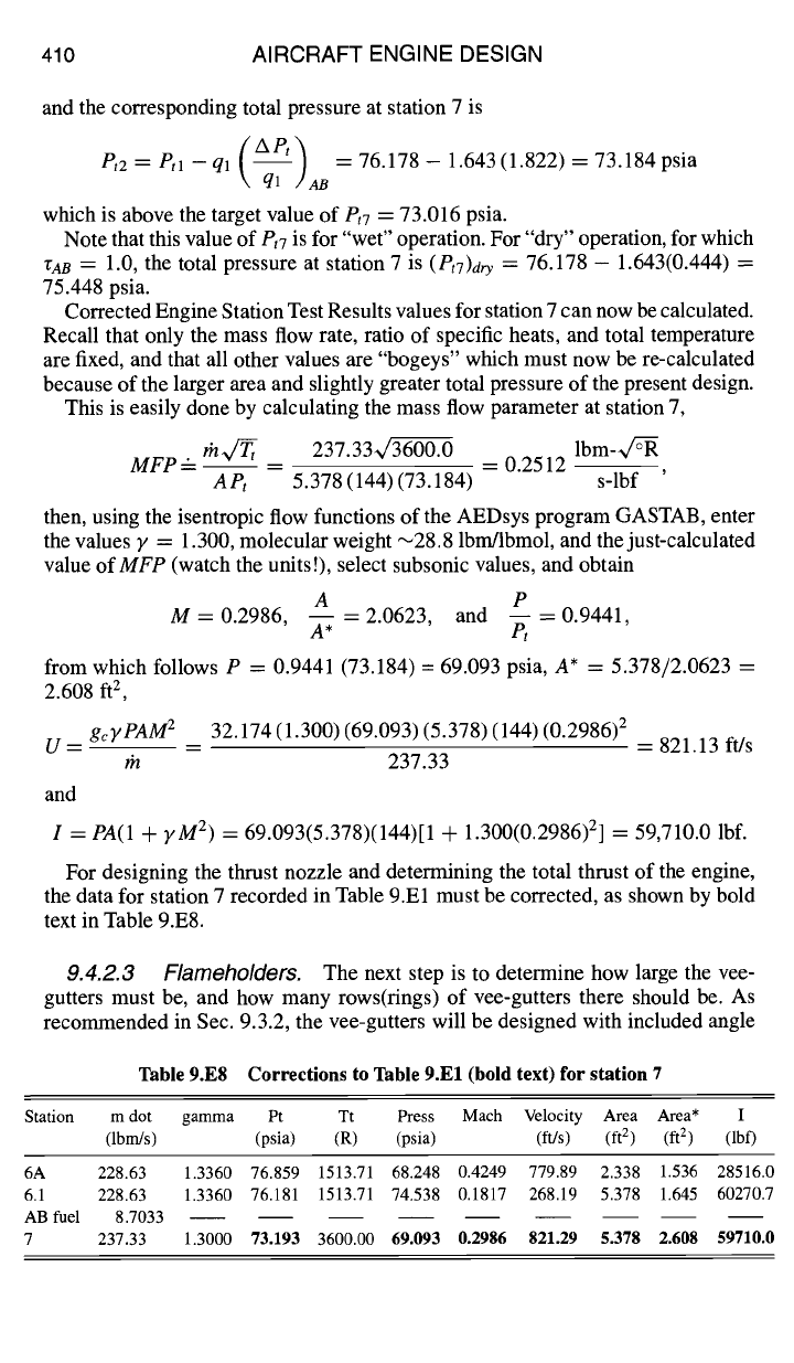
Table 9.E6
DESIGN: COMBUSTION SYSTEMS
Dimensions of AAF engine afterburner mixer + diffuser
shown in Fig. 9.E9 a
407
Station 1 (6A) Station m Station 2 (6.1)
ro
(in.) 15.7 15.7 15.7
ri
(in.) 11.8 5.0 0.0
rm (in.) 13.75 10.35 7.85
H (in.) 3.9 10.7 15.7
A (ft 2) 2.338 4.840 5.378
aLto =
35.2 in. Ld = 5.0 in.
separates from both walls, which causes stirring, which in turn enhances the mixing
of the co-flowing streams. This suggests that a combined mixer + diffuser might
be a good idea. However, if design data for such a combined mixer -t- diffuser
exists, it must be proprietary to the engine manufacturers, as no references could
be found in the open literature.
Consequently, for preliminary design purposes, the total pressure losses caused
by mixing and flow diffusion must be calculated individually, as if the processes of
mixing and diffusion occurred in axially separate components, whereas in actual
fact, the mixing and diffusion processes will be combined into a single component.
9.4.2.2 Diffuser.
All of the design relations for an annular flat-wall + dump
diffuser were presented in Sec. 9.3.2, in Eqs. (9.122-9.128). Assuming a flat-wall
diffusion efficiency
rio,.
= riD9 o = 0.90 and an overall area ratio
AR
=
A6.1/A6A
=
5.378/2.338 = 2.30, Eq. (9.127) gives the optimal area ratio for transition from
flat-wall to dump diffuser
A,.op t
=
(2.338)(0.90)(2.30) = 4.840 ft 2.
From the annular geometry relations Eqs. (9.122) and (9.123), all of the dimen-
sions for the diffuser can be calculated, and are summarized in Table 9.E6. The
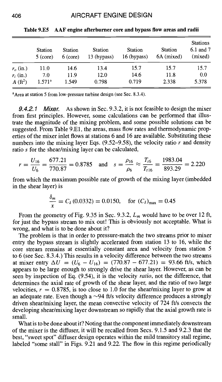
resulting combined mixer + diffuser is drawn to scale in Fig. 9.E9.
From Eq. (9.128), the combined or overall diffusion efficiency is 0D = 0.903,
essentially equal to that assumed for the flat-wall section alone.
A few comments about this design are in order. First, it may seem optimistic to
assume a diffusion efficiency as high as 0D ---- 0.9, but it must be borne in mind
that the combined mixer + diffuser has already been assessed a total pressure loss
station 6A station 6.1
Fig. 9.E9 Combined mixer + diffuser with dimensions given in Table 9.E6 (to scale).
408 AIRCRAFT ENGINE DESIGN
for mixing alone. Secondly, the centerbody length
Lm
~
3 ft may seem somewhat
long, but one design goal is to provide adequate length for mixing of the core
gas and bypass air streams, as well as efficient diffusion. Finally, if a worst-case
diffusion efficiency of OD = 0.6 were to be assumed, the centerbody length would
be reduced to
Lm
"~ 1 ft, just one-third of the design value! It appears that there
are some interesting trade-offs to be considered here.
All properties at station 6.1 can now be calculated, as follows:
1) At diffuser entry station 1, using values from Table 9.El for station 6A,
ql
= Ptl
-
P1 = 76.859 - 68.248 = 8.611 psia,
or
ql = ~yP1M~
= 0.5 (1.336) (68.248) (0.4249) 2 = 8.231 psia
To be conservative, the larger value ql = 8.611 psia will be utilized.
2) The total pressure loss coefficient, from Eq. (9.66), is
1
\ ql / O ql
( II
= 1 (2.50) 2 (1-0.903) = 0.0787
from which the total pressure at station 6.1 is
Pt2 = etl- (Aet~
ql =
76.859- 0.0787(8.611) = 76.181 psia,
\ ql /D
and the static pressure, from Eqs. (9.62-9.64), is
( 1
P2 =- PI -k- 1 -- ~ rlDql
= 68.248 + 1 (2.30)z, /
= 74.538 psia
and the dynamic pressure is q2
=
Pt2
- P2 =
76.181 - 74.538 = 1.643 psia.
3) The Mach number at station 6.1 is determined by
_/2q2 ~1.336(74.538)2(1.643) - 0.1817,
M2 = V~2 =
for which the corresponding velocity is
gcP2A2M 2
32.174(74.538)(5.378)(144)(0.1817) 2
U2 - - = 268.19 ft/s
rn 228.63
and the stream thrust function at station 6.1 is
I2 = PzA2(1 + yM 2) = 74.538(5.378)(144)[1 + 1.336(0.1817) 2] = 60,270.7 lbf
All of these values are summarized on a new line to be added to the Engine
Station Test Results sheet of Table 9.El for station 6.1, given in Table 9.E7.
II
I
+
II
+
0
4~
4~
II
b~
b~
""
(1) ~0 ~
~
.... "'~ "~-~ ~ ~ ~' ~'~ ~--b ~'~
-~'~ *'--' ~ ~" ..-~ ~ ~'~
~ ....
o~.~
~ ~o ~ ~ ~.~ -
~-~ ~o~'--~ ~ o
II C~ {'~ ~" ~ ~
__~ ~-- II ~"
II
I
-t-
II
I
-t-
0
II
~,,,°
o~o
~.~
• ::i~
~.~~
I1"
II
I
-t-
0 0
N.~"
~Na
• ~
=,o~ I
bJ IxJ
.~.oo
~,~ oo
.w.~
.~.oo
tn hJ
~000
.~.o
oo
.u,.~
-q b~
~o oo
O~
/-x
~m
u
r.
O0
z
o
o- 0
c
00
I
.~" 0
z
~" O0
~" .<
O0
rll
00
@
0
qD
410 AIRCRAFT ENGINE DESIGN
and the corresponding total pressure at station 7 is
Pt2
= Ptl-ql
(APt ~ =
76.178- 1.643(1.822)= 73.184 psia
\ ql ~lAB
which is above the target value of
Pt7
= 73.016 psia.
Note that this value of
Pt7
is for "wet" operation. For "dry" operation, for which
ZAB
= 1.0, the total pressure at station 7 is
(PtT)d,-y
= 76.178 -- 1.643(0.444) =
75.448 psia.
Corrected Engine Station Test Results values for station 7 can now be calculated.
Recall that only the mass flow rate, ratio of specific heats, and total temperature
are fixed, and that all other values are "bogeys" which must now be re-calculated
because of the larger area and slightly greater total pressure of the present design.
This is easily done by calculating the mass flow parameter at station 7,
MFP'-- th4Ttt _
237.33~ = 0.2512 lbm-~/Z-R
APt
5.378(144)(73.184) s-lbf
then, using the isentropic flow functions of the AEDsys program GASTAB, enter
the values y = 1.300, molecular weight ~28.8 lbrn/lbmol, and the just-calculated
value of
MFP
(watch the units !), select subsonic values, and obtain
A P
M = 0.2986, -- = 2.0623, and -- = 0.9441,
A*
Pt
from which follows P = 0.9441 (73.184) = 69.093 psia, A* = 5.378/2.0623 =
2.608 ft 2,
gcyPAM 2
32.174 (1.300) (69.093) (5.378) (144) (0.2986) 2
U- -- -- = 821.13 ft/s
rh 237.33
and
I = PA(1 +
yM 2) = 69.093(5.378)(144)[1 + 1.300(0.2986) 2] = 59,710.0 lbf.
For designing the thrust nozzle and determining the total thrust of the engine,
the data for station 7 recorded in Table 9.El must be corrected, as shown by bold
text in Table 9.E8.
9.4.2.3 Flameholders.
The next step is to determine how large the vee-
gutters must be, and how many rows(rings) of vee-gutters there should be. As
recommended in Sec. 9.3.2, the vee-gutters will be designed with included angle
Table 9.E8 Corrections to Table 9.El (bold text) for station 7
Station m dot gamma Pt Tt Press Mach Velocity Area Area* I
(lbm/s) (psia) (R) (psia) fit/s) (ft 2 ) (ft 2 ) (lbf)
6A 228.63 1.3360 76.859 1513.71 68.248 0.4249 779.89 2.338 1.536 28516.0
6.1 228.63 1.3360 76.181 1513.71 74.538 0.1817 268.19 5.378 1.645 60270.7
AB fuel 8.7033
7 237.33 1.3000 73.193 3600.00
69.093 0.2986 821.29 5.378 2.608 59710.0
DESIGN: COMBUSTION SYSTEMS 411
2 0 = 30 deg. In the present design, in order to meet the goal value of total pressure
loss, a sub-optimal
W/H
= 0.4 and corresponding blockage B =
D/H
= 0.314
will be utilized, where D is the lateral dimension or height of the vee-gutters and
H is the channel height or "pitch" between vee-gutters.
Equation (9.134) states that, for
W/H
---- 0.4, H must be greater than 1.042
times the product of approach velocity
U6.1
and
tBo, the
residence time at blowout
in the mixing layer at the edge of the recirculation bubble. Because U61 has been
determined from the design of the afterburner diffuser, the sole task remaining is
to use the AEDsys chemical kinetics program KINETX to determine
tBo.
Establishing inputs for KINETX requires some rather tedious calculations to
determine the composition of the mixture of core gas combustion products with
turbine cooling air and fan bypass air. The required steps are:
1) Find the composition of combustion products entering the high pressure
turbine at station 4. This can be done from stoichiometric "complete combustion"
calculations, because minor or pollutant species have a negligible effect on this
calculation, or more easily by using either of the two AEDsys programs EQL
or KINETX. Either way, the mass-specific mol numbers of major combustion
products at station 4 are found to be
no2
= 4.354 × 10 -3 lbmolsO2/lbmmixture
nN2
= 2.669 × 10 -2 lbmols N2/lbmmixture
ni42o
= 1.928 x 10 -3 lbmolsH20/lbmmixture
n¢o2
= 1.780 × 10 -3 lbmols CO2/lbmmixture
The mass-specific mole numbers at station 16 are those for air alone,
no2
= 7.098 × 10 -3 lbmols O2/lbmair
nN2
= 2.669 × 10 -2 lbmols N2/lbm air
2) From Table 9.El, the mass flow of main burner combustion products at
station 4 is 106.94 Ibm/s, and the sum of the air mass flow rates for both turbine
cooling and fan bypass is 121.69 lbm/s. The mole numbers in the combined streams
at stations 6A and 6.1 are therefore calculated to be
no2
= 5.815 × 10 -3 molsO2/lbmmixture
nN2
= 2.669 X 10 -2 molsN2/lbmmixture
ni42o
---- 9.018 x 10 -4 molsH20/lbmmixture
ncoz
= 8.326 × 10 -4 molsCO2/lbmmixture
This is the composition of the gas approaching the flameholders and being
entrained into the mixing layer at the edge of the recirculation bubble.
3) Equations (9.59) and (9.60) show that the mixing layer entrains essentially
equal amounts of cold gas and hot recirculation products, which corresponds to a
recirculation ratio
RR
= 0.5 for input to KINETX.
4) With the mass flow rate, gas composition, temperature and pressure estab-
lished at station 6.1, with recirculation ratio
RR
---- 0.5, and the afterburner fuel
mass flow rate as inputs to KINETX, there results
tso ~
8.5 × 10 -5 s.
It is now possible to determine the minimum channel height H from Eq. (9.134):
Hmin = 1.042 (U6.1
tBo)
= 1.042 (268.19) (8.5 × 10 -5) = 0.0238 ft x 12 "~ 0.3 in.
412 AIRCRAFT ENGINE DESIGN
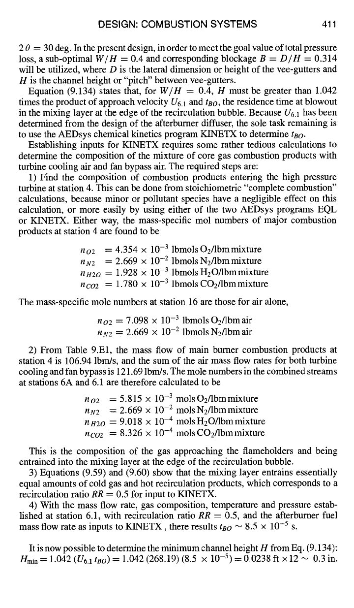
£
Fig. 9.El0 Comparison of afterburner length using two or three rings of vee-gutters
(to scale).
For a design blockage of B = 0.314, the corresponding minimum value of
vee-gutter height is
Dmi n = Bnmin =
0.314(0.3) ~ 0.1 in. In other words, a ~0.1
in. vee-gutter would be marginal, operating near extinction or blowout. To ensure
stable flameholding, operating far away from blowout, both the vee-gutter size D
and spacing H will have to be significantly larger than the minimum values, while
maintaining the design ratio B =
D/H
= 0.314. Typically, using a factor of 10
to ensure a "significantly larger" margin, the vee-gutter dimension D should be
greater than 1.0 in.
The maximum number of vee-gutter tings is determined by dividing the height
of the total afterburner flow area, H6.1 = 15.7 in., by the minimum vee-gutter
channel height nmin, and rounding down:
[Nvee]max =
15.7/1.0 "-~ 15. As long as
there
are fewer
than 15 rings of proportionately sized (B = 0.314) vee-gutters, they
should perform their flameholding function satisfactorily. The choice of number of
rings therefore depends on other design considerations such as afterburner length,
stealth shielding, and structural and manufacturing complexity.
Figure 9.El0 shows graphically the effect on afterbumer length of two versus
three tings of afterbumers. Note that, compared to the comparison of one versus
two tings shown in Fig. 9.41, the effect of more tings of smaller vee-gutters is
diminished as the number of tings increases. This is because the axial length
scale reduction goes from 1:2 to 2:3. Bearing in mind the complexity of adding
as many spray bars and manifolds as vee-gutter tings, there does not appear to
be a compelling reason to increase the number of vee-gutter rings beyond three
or four. For the present design, three tings will be satisfactory, for which H =
15.7/3 = 5.25 in, and D = (0.314)(5.25) = 1.65 in. For this design, the distance
from the nose of the vee-gutter to where the flame strikes the wall, still assuming
flame spread at 17 deg for lack of better information, is approximately 20 in. This
dimension should probably be increased to 24 in or even 30 in, because of our
imprecise knowledge of the flame spread angle, and of course while respecting
constraints on axial length as a result of the "packaging" of the entire engine within
the airframe.
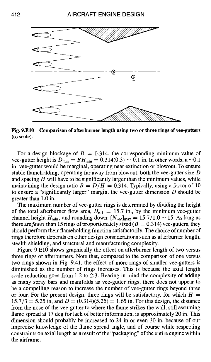
DESIGN: COMBUSTION SYSTEMS 413
station 16
]~ Lm t Ld---~_
"~ station 6.1
Fig. 9.El1 "No-mix" diffuser for alternative example afterburner design.
9.4.2.4 Spray bars.
Lacking more information or better guidance, three
rings of spray bars will also be chosen, each spray bar to be located directly
upstream of each vee-gutter, and tucked back inside the diffuser tailpipe to conserve
axial space.
9.4.2.5 Summary.
The overall length of the afterburner can now be calcu-
lated, as the sum of the calculated or estimated lengths of 1) the ducting between
stations 5 and 6 and between stations 13 and 16, [12 in.]; 2) the combined mixer ÷
diffuser + spray bars, [45 in.]; 3) the flameholding and flame spread section,
[24 in.]; for a total length
LAB
= 12 + 45 + 24 = 83 in -~7 ft.
9.4.2.6 Alternate "no-mix" afterburner design.
The difficulty of mixing
the core gas stream with the bypass fan air stream has been emphasized earlier in
this section. An alternative approach, mentioned in Sec. 9.3.2, is to not try to mix
the two streams at all, but simply allow them to co-flow through the diffuser, as
shown in Fig. 9.El 1.
In this "no-mix'approach, the vee-gutter flameholders would be located at the
entrance to the "dump" portion of the diffuser, the intermediate station m in
Fig. 9.E9. If the flameholder were to be located at the end of the tailpipe sec-
tion, station 6.1, the flow dispersion in the dump section would result in unpre-
dictable, large-scale stirring between the two streams, as described in Sec. 9.1.5,
which would defeat the design premise of a two-stage, two-stream "no-mix"
afterburner.
It will be assumed that the two streams are separated by a "slip surface" across
which no mixing occurs. As can be seen from Fig. 9.35 and related estimates
made earlier in this section, this is not a bad assumption. Because both co-flowing
streams are subsonic, the static pressure is always matched in both streams, and
so Eq. (9.64) can be used to find the areas of the two streams at station m in Fig.
9.E9, as follows:
AP= {TlDql(l--~-~)}core: {tlDql(1--A~)]fa n
The area ratios of the two streams are
ARcore : otAm/A6
and
ARyan = (1
-or) x
Am~A16,
where ot is the area fraction of the core stream at station m, and where
Am
: 4.840 ft 2 from Table 9.E6. The dynamic pressures in the two streams
414 AIRCRAFT ENGINE DESIGN
at entry can be found from the difference between static and total pressures in
Table 9.El, ql
core = (Pt
-
P)6 =
78.129 - 71.533 = 6.596 psia, and
qlfan
=
(Pt -
P)16 = 83.391 - 71.570 = 11.821 psia. Assuming the diffusion efficiencies
in the two streams to also be equal, Eq. (9.64) can now be solved to find the core
stream area fraction u = 0.7963, and the corresponding two areas at station m
as
Am cor e ~-
0.7963(4.840) = 3.854 ft 2, and
Amfan ~--
(1 -
0.7963)4.840
=
0.9859 ft 2. From the annular geometry relations Eqs. (9.122), the radius of the
slip surface dividing the two streams at station m is found to be
rslip
-- 14.2 in.,
so the radial heights of the two streams are
Hm~ore
= (14.2 - 5.0) = 9.2 in., and
Hmfan =
(15.7 - 14.2) = 1.5 in.
Applying Eq. (9.64) to either stream, and assuming a diffusion efficiency Oi~ =
0.9, the station pressure at station m is found to be
Pm=
76.53 psia.
From mass continuity the corresponding stream velocities at station m are
A6
1.549
Urn
core =
U6 Am
co-""~e --
(770.87) 3.854 -- 309.82 ft/s,
and
A16 0.719
Urn fan
= U16 ~n --
(677"21)0.9859 -- 493.88 ft/s
and the static temperatures in both streams are essentially equal to their respective
total temperatures, listed in Table 9.El for stations 6 and 16.
The gas compositions of the two streams have already been determined earlier in
this section. With all inputs to the AEDsys software program KINETX now fixed,
including the design afterburner exit temperature of
Tt
= 3600°R, the blowout
residence times in the two streams are found to be
tBo
core
=
1.49 × 10 -4 s and
tBofan
= 7.07 x 10 -5 s, and the required fuel mass flow rates in the two streams
are rhfcore
= 3.331 lbm/s and
l~lffan =
5.795 lbm/s.
Assuming the optimal wake width to channel height ratio
W/H
= 0.5,
Eq. (9.135) gives the minimum channel widths for flameholding for the two
streams,
Hcore > U6 rBOcore
= 309.82 (12) (1.49 × 10 -4) ---- 0.55 in., and
Hfa, >
U16
~'BOfan =
493.88(12)(7.07 × 10 -5) = 0.42 in. The maximum number of vee-
gutter rings in each stream is determined as before by dividing the radial pas-
sage height by a safety margin of 10 times the minimum height required for
flameholding and rounding down,
[Nvee]core =
9.2/10(0.55) ~ 1, and
[Nvee]fa n =
1.5/10(0.42) ~ 0.
For the core stream with a single vee-gutter ring, and with the optimal blockage
B = 0.417 for a 30 deg included angle vee-gutter, as given by Eq. (9.137), the
corresponding vee-gutter lateral dimensions are
Dcore
= 0.417(9.2) = 3.84 in.
This corresponds to a shear layer residence time ts
=
ncore/Urncore =
9.2/
(12) 309.82 = 2.48 × 10 -3 s, which is a comfortable ~16 times the minimum
residence time for flameholding,
tBocore
= 1.49 × 10 -4 s. In the fan stream,
a single vee-gutter with the same blockage would required a vee-gutter of di-
mension
Dfa,
= 0.417 (1.5) = 0.62 in. This gives a shear layer residence time
ts = Hfa,,/Umfa,
= 1.5/(12) 493.88 = 2.53 × 10 -4 s, which is less than ~3.6
times the minimum residence time for flameholding,
tsofa~
= 7.07 × 10 -5 s.
There are some problems with this alternative flame stabilization design: 1) The
required fuel mass flows to achieve the design exit temperature of Tt = 3600°R
DESIGN: COMBUSTION SYSTEMS 415
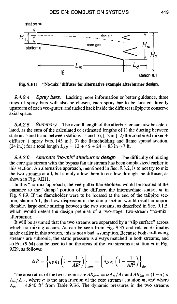
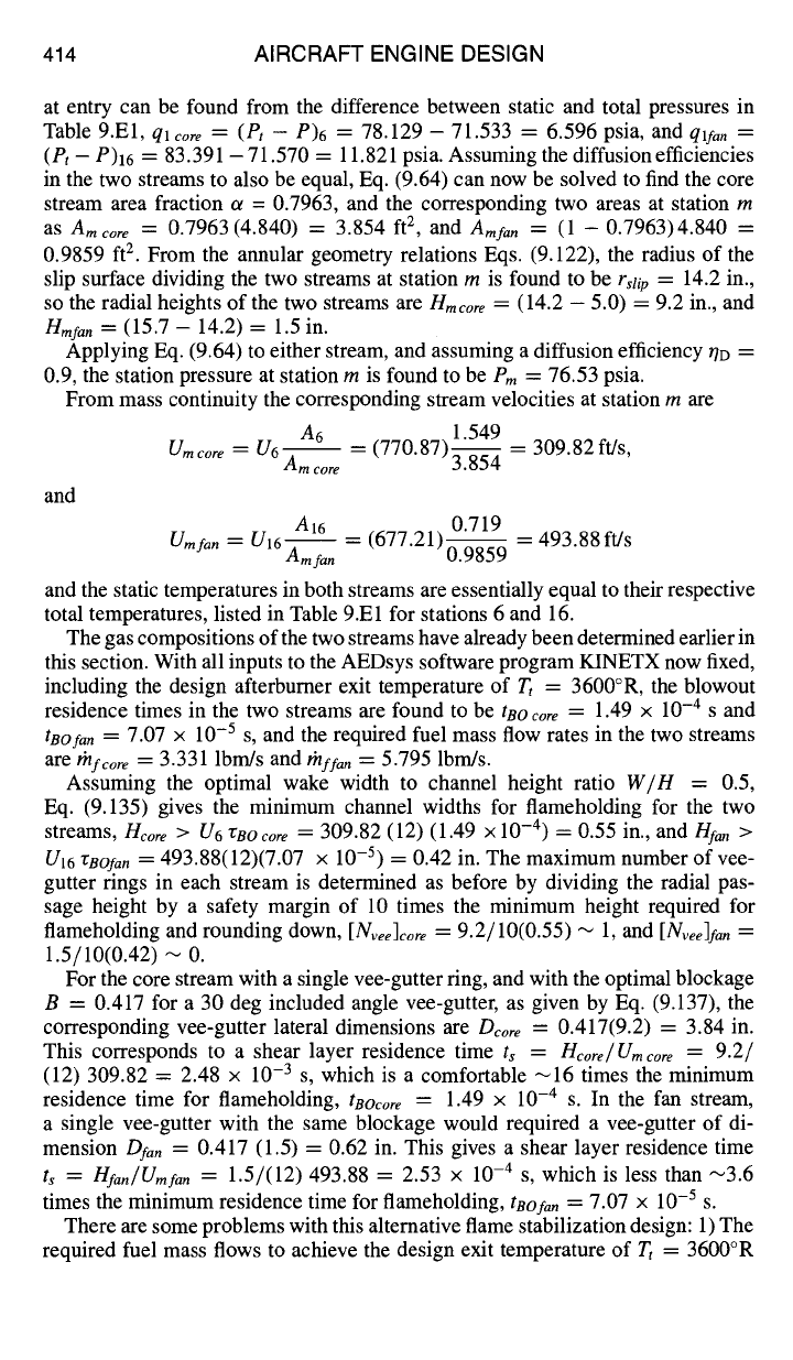
Fig. 9.E12 Alternative "no-mix" design arrangement of vee-gutter rings and spokes.
in both streams add up
to/'r/f =
3.331 + 5.795 = 9.126 Ibm/s, nearly 5% greater
than the fuel flow required for the mixed-stream design, and 2) The 9.2-in. height
of the core stream is not quite large enough to accommodate two flameholders
with good stability, so a single, D = 3.8 in. vee-gutter is required, whereas the
1.5-in. height of the fan stream can accommodate only a single D = 0.625 in.
vee-gutter, for which the residence time is only a marginal 3.6 times greater than
the minimum required for flameholding.
One workaround to the flameholder size problem, used on at least one currently
operational engine and as illustrated in Fig. 9.E12, is to attach radial spokes of vee-
gutter shape and lateral dimension great enough to give a residence time 10 times
the blowout value,
Dfa,,
= 1.76 in. The spokes can be spaced circumferentially
with appropriate solidity to maintain the desired blockage B = 0.417 in the fan
stream.
However, because the root area of the spokes is in the core stream, the ring
vee-gutter must be reduced in lateral dimension
Dcore
to, say, 3 in., to offset the
core gas blockage of the root area of the spokes. Further complicating this design
solution, additional inward-protruding spokes must be provided to add back the
needed blockage in the portion of the core gas stream inboard of the vee-gutter
ring.
A stealth variation of this design is to locate the single vee-gutter ring in such a
way as to hide the moving blades at low-pressure turbine exit, in case the turbine
blades are not already hidden by ducting as in the present design.