Mattingly J.D., Heiser W.H., Pratt D.T. Aircraft Engine Design
Подождите немного. Документ загружается.

152 AIRCRAFT ENGINE DESIGN
Given
ht2.5i,
the subroutine FAIR will give the reduced pressure Pr
t2.5i.
Thus the
low-pressure compressor pressure ratio is calculated using Eq. (4.9b) written as
er t2.5i
7'i'cL -- --
(5.6d)
Prt2
For a calorically perfect gas, Eqs. (5.6a) and (5.6b) become
yrf =
{l
+
Of(rf -
1)}~
(5.6b-CPG)
and Eqs. (5.6c) and (5.6d) become
Yc
zrcL = {1 +
rIcL(72cL --
1)}~c =7~
(5.6d-CPG)
High-pressure compressor temperature ratio
(rcH). The high-pressure
spool power balance of Eq. (4.21a) can be rearranged to yield
/ r
1 + (1 -
rtH)rlmH
(1 -- fl -- el -- e2)(1
+ f) ~ Lrr'CcLrlmPH.] thoho
"gcH
1 - el(1 -
"CtH)rlmH
(5.7)
so that
where
Ptl6 Pt2~ f Tf f
Pt6 Pt27rcL712cHYlYb71JtHT(tL 2TcL71JcHT@JrtHTftL
Ptl6
_ ~ f et6
(5.9)
P16
712cLT~cHTgbTt'tHTftL P6
For a calorically perfect gas, h0 =
cpcTo
in Eq. (5.7).
High-pressure compressor pressure ratio (Zrc,).
From the definition of
high-pressure compressor efficiency, Eq. (4.9c),
ht3i
= h/2.5{1 +
OcH(rcH --
1)} (5.8a)
Given
ht3i,
the subroutine FAIR will give the reduced pressure
Pr t3i.
Thus the
low-pressure compressor pressure ratio is calculated using Eq. (4.9c) written as
er t3i
7rcH - (5.8b)
Pr t2.5
For a calorically perfect gas, Eqs. (5.8a) and (5.8b) become
7rcH = {1 +
tlcH(rcn --
1)}3 (5.8b-CPG)
Mach number at station
16 (M16). The definition of total pressure yields
MI6 once
Pt16/P16
is evaluated. Since Pt6 = P6, then
P,6 Pt16 Pt6
P16
et6 P6
ENGINE SELECTION: PERFORMANCE CYCLE ANALYSIS 153
For the flow to be in the proper direction,
Ptl6
> P16.
With
Ptl6/P16
and
Ttl6
known, then the compressible flow subroutine RGCOMP yields M16. For the flow
to be subsonic, M16 < 1.0.
For a calorically perfect gas, Eq. (5.9) becomes
Yt
Pt16
ff~f Pt6 ffrf (l_4_~]t-lM~X~ yt''7-1
P16
7rcL37JcHTfbTftHTftL P6 7~'cLY'gcHY'(bTftHY'ftL
\]2
(5.9a-CPG)
and the Mach number at station 16 is given by
M16 ---- ~
\-~-t6] - 1
(5.9b-CPG)
Mixer bypass
ratio (o~').
the mass flow parameter,
or
From the definition of the mixer bypass ratio and
at ~/16
Ptl6
A16
MFP16 /
Tt6
(4.8f)
-- I~17 -- Pt6 "~6 ~ VTtl6
r
y't'f A16
MFP16 / Tt6
13/I
(5.10)
T(cL~cHTrbTrtH~tL
A6
MFP6 VTtl6
For a calorically perfect gas, Eq. (5.10) is unchanged. The mixer bypass ratio is
iterated, as shown in Fig. 5.3a, until successive values are within 0.001.
Engine bypass ratio
(or). From the definitions of the engine and mixerbypass
ratios,
O/ ..... O/t{(1 -- fl -- S1 -- ~'2)(1
+
f) +
El -~- 5"2}
rhc rn6 rhc
or
Ot = Oft{(1 -- fl -- 81 -- 82)(1
+ f) + el + e2}
Equation (5.11) is unchanged for a calorically perfect gas.
(4.8a)
(5.11)
Mixer enthalpy ratio
(rM). Equations (G.3) and (G.4) yield
"C M
1 + Ot'(Trrf/'CZ'rmlVtHVm2"rtL)
1 +or'
For a calorically perfect gas, Eq. (5.12) becomes
1 +
Olt('~rTf/'f)~Tml'gtHTm2"CtL)
(5.12)
rM = (5.12-CPG)
1 + ot'cpc/Cpt
154 AIRCRAFT ENGINE DESIGN
Mach number at station 6A
(M6A).
to the ideal mixer, we have
~
1
-1- Y6AM2A
__ R~
(1
M6A V Y6
rearranged into
From the momentum equation applied
q- >'6M62) +
A16/A6(1 -t-
Y16M26)
M6(1 + or')
(4.29)
-- 1
+ Y6AM2A
m6a
V Y6A Constant
(5.13)
where
Rf-R~6T6 (1 +
y6M 2) -}- A16/A6(1 -1- F16M216)
Constant
"1 --V 76 M6(l+ot')
For a given value of the total temperature and fuel/air ratio at station 6A, Eq. (5.13)
is solved by functional iteration in combination with the isentropic temperature
ratio
(Tt6A/ T6A).
For a calorically perfect gas, the Mach number at station 6A (M6A) can be solved
for directly using the following system of equations:
ok(M6,
~6)~-
M6211 +
(Y6 --
1)M2/2].
(1+ y6M2) 2 '
~b(M16, Y16)~-"
M2611 +
(YI6 --
1)M26/2]
(1 + Y16M26) 2 (5.13a-CPG)
R6 + ot1R16
Cp6 A
R6A
= ; ~6A -- (5.13b-CPG)
1 + or'
Cp6A -- g6a
, 1
y6R6a
*---- (l+ot)/I - +~'./'~ -_/
/L~/O(M6, y6)
~ Y~-~-~6 ~ ~(~6, ~6)
Y6AR~ rM
(5.13c-CPG)
M6A
= (1 -- 2y6A) + ~i--- 2(Yaa + 1)~ (5.13d-CPG)
Mixer total pressure ratio
(TrM).
Equation (G.6) gives
T~A6
MFP(M6, Tt6,
f6)
7rMideal
---- (1 + t~')V
Tt6 A6A MFP(M6A, Tt6A,
f6A)
(5.14a)
ENGINE SELECTION: PERFORMANCE CYCLE ANALYSIS 155
The mixer total pressure ratio is the product of the frictional loss (7rM
max)
and the
mixing loss (rrM
ideal)
or
Y/'M = 7rM maxTrM
ideal
(5.14b)
For a calorically perfect gas, Eq. (1.3) is used to calculate the mass flow param-
eters in Eq. (5.14a), and Eq. (5.14b) is unchanged.
Mach number at station
8 (Ms). The Mach number at station 8 depends on
the pressure ratio
Pt9/Po
with the afterbumer off (dry). This ratio must be equal
to or greater than that corresponding to Mach one for the flow to be choked at
station 8. We write
[,,91
Po J dry = Zrr 2I'dYt'cL2TcHT(bYTtH~tLY'I'M 7~AB dry2Tn
(5.15)
The compressible flow subroutine RGCOMP is input this total to static pressure
ratio in combination with the fuel/air ratio (f6A) and the Mach number at station
9 (M9) is output for matched static pressures (P9 = P0) and afterburner off. If
/149 >_ 1, then M8 = 1 else M8 =/149.
For a calorically perfect gas, Eq. (5.15) is unchanged, and the Mach number at
station 9 (M9) is solved directly from Eq. (1.2) or
M9 ....
1
Y6A--1 LPo.ldry
If M9 >_ 1, then Ms = 1 else M8 = M9.
Mach number at station
6 (M6). M6 can be obtained from the mass flow
parameter
(MFP6)
once the latter is determined. Writing the ratio of mass flow
rates at station 8 to station 6 for nonafterbuming operation gives
th__88 -= Pt8dry A8dry
MFP8 T~t6 or'
th6 Pt6 A6 MFP6 V Tt8 = 1 +
Solving for the mass flow parameter at station 6 yields
A8dry MFP8 J Tt6
MFP6 = 7(MTgAB dry A6 1 Jr-
at
Tt6A
(5.16)
!
With
MFP6
known, the compressible flow subroutine RGCOMP yields/146 < 1.
The Mach number at station 6 is iterated, as shown in Fig. 5.3b, until successive
values are within 0.0005.
For a calorically perfect gas, Eq. (5.16) is unchanged, and the Mach number at
station 6 (M6) is solved for using Eq. (1.3).
Engine mass flow rate
(rho).
Conservation of mass and the definition of the
bypass ratio (a) yield
rh 4,
rh0
(1
+
o/)/~/C
(1
+
°t)(1 -- fl -- el --
e2)(1 -t- f)
156 AIRCRAFT ENGINE DESIGN
From Eq. (1.3)
~/4 t --
Pt4,A4'MFP4, Pt4A4,MFP4,
where, by assumption,
Pt4
= Pt4,
and
Zt4 = Zt4,.
Combining the preceding two
equations and denoting station 4' as 4 gives
(1 +
ol)PoTgrY'gdT~'cLT"gcH~Tfb
A 4
rho = (1 ~~1 ~ e2--~+f-)
vt-T-~t4 MFP4
(5.17)
For a calorically perfect gas, Eq. (5.17) is unchanged.
Mach number at station
9 (Mg). The Mach number at station 9 depends on
the pressure ratio
Pt9/P9.
We write
Pt9 Po
~9 ~-- "-~9YgrTgd2"[cL37:cHT(b2TtHTgtL71:MT"(ABJ'gn
(5.18)
The compressible flow subroutine RGCOMP is input this total to static pressure
ratio in combination with the fuel/air ratio at the afterburner exit (fT) and the Mach
number at station 9 (M9) is output.
For a calorically perfect gas, Eq. (5.18) is unchanged, and the Mach number at
station 9 (M9) is solved directly from Eq. (1.2), or
M9= T9j -1
5.2.6 Iterative Solution Scheme
Because there are 24 dependent variables and 24 equations, there are many
different ways that the off-design cycle analysis equations can be ordered to obtain
a solution. Our experience convinced us that the mixer bypass ratio (u'), the core
entrance Mach number to the mixer (M6), and the engine mass flow rate (#to) are
the preferred iteration variables. The iterative solution scheme shown in Figs. 5.2
and 5.3 has been custom tailored to this application so that it will converge on a
solution for a wide range of input values. Note that M6 is the second dependent
variable that is iterated and successful solution of the off-design performance
depends on its convergence. Referring to the functional relationships listed in
Sec. 5.2.5, note that values of or', M6, and rn0 are estimated to begin a solution
of the off-design equations. Making reasonable initial estimates can significantly
reduce the number of iterations required for a solution. Conversely, sufficiently
inaccurate initial estimates can prevent convergence altogether. Because M6 varies
only slightly over the off-design range of the engine and rh0 has a small influence
in the calculation of rcL in Eq. (5.5b), each has a secondary influence on the
iteration scheme. The reference point values of M6 and rh0 can therefore serve as
ENGINE SELECTION: PERFORMANCE CYCLE ANALYSIS 157
satisfactory initial estimates for these two terms, or
M6 = M6R (5.19a)
rno = #10g (5.19b)
However, the mixer bypass ratio
13/
c~' = (5.19c)
(1
-- fl -- el -- e2)(1 -1- f) q-
gl -? S2
varies considerably over the expected flight envelope because it is proportional to
the engine bypass ratio oe (see Figs. 4.8 and 4.11). We have found that a reasonable
initial estimate of or' can be obtained using Eq. (5.19c) with o~ estimated by
To rr
ot ~ otR---- (5.19d)
TOR 72rR
where the altitude and Mach number effects on ot are accounted for by To and rr,
respectively. When using the AEDsys software for repeating calculations where
only one off-design independent variable is changed, the initial values of or', M6,
and rn0 for each subsequent calculation are taken from the solution already
converged.
Certain features of the programmed iteration methods used in the AEDsys per-
formance computations deserve highlighting, as follows:
1) If either the pressure ratio at the splitter plate (Pt 16//)16 ) or the Mach number
in the fan stream
(M16) is out
of limits, the core entrance Mach number to the
mixer (M6) is incremented by 0.01. If
M16 is too low, M6
is increased.
2) If the new value of the mixer bypass ratio (e() calculated by Eq. (5.10) is not
within 0.001 of the preceding value, then Newtonian iteration is used to converge
to a solution.
3) Functional iteration is used for both core entrance Mach number to the mixer
(M6) and the mass flow rate (rn0).
5.2.7
Variation in Engine
Speed
As is shown in Sec. 8.2.1, the change in total enthalpy across a fan or compressor
is proportional to the shaft rotational speed (N) squared. For the low-pressure
compressor, we can therefore write
ht2.5 - ht2 = KIN 2
which can be rewritten, using referencing, as
!
i
NL _ / ht2.5 - ht2 / ht2 "CcL -- 1
Nt~ V ht2"5R
-htzR
V ht2R rcU¢ -- 1
_~ht0 teL--1 ,.~00
rcL--1
h toR vcz~ -- 1 )90R ~cLtf-- -1
(5.20a)
158 AIRCRAFT ENGINE DESIGN
Likewise, for the high-pressure compressor, we have
[
/
NIt / ht3
- ht2.5 [ ht2.5
"rcH -- 1
V V
NoR ht3R --ht2.5R ht2.5R
rcl~R - 1
~ hto rcL rcH -- 1 ~ / O0 tel rcH -- 1
t
-- ht0~ rcLR rc/4R- 1 -- V00R rcLa rc,qR -- 1 (5.20b)
For a calorically perfect gas, Eqs. (5.20a) and (5.20b) are unchanged.
5.2.8 Software Implementation of Performance Calculations
The performance computer program embedded in the Engine Test portion of
the AEDsys program uses the system of equations listed in Appendix I, which
is based on the solution technique outlined in Secs. 5.2.4-5.2.6 and portrayed in
Figs. 5.3a and 5.3b. The performance program is intended to be used in conjunction
with the reference point program ONX discussed in Chapter 4.
The reference point of the engine whose performance behavior at off-design is to
be investigated is initially obtained using the computer program ONX. The inputs
and outputs of the reference point analysis are the source of the reference values
(subscript R) used in the performance computer program. The inputs listed next
for the performance analysis, therefore, include those required for the reference
point analysis as well as those that specify and are unique to the performance point
being analyzed (e.g., flight conditions and limits).
Sample printouts of the reference point (ONX) and off-design calculations
(Engine Test portion of AEDsys) for a typical performance analysis with and
without afterburning are given in printout samples A, B, and C. AEDsys will auto-
matically transfer all input values (reference values) from ONX for performance
computations other than the Performance Choices and Engine Control Limits. The
output consists of overall engine performance parameters, component behavior in-
formation, and a large selection of internal variables of interest. In fact, sufficient
output data are provided to allow the hand calculation of any desired quantity not
included in the printout.
The Engine Test portion of the AEDsys program is a powerful learning and
design tool. The AEDsys program will automatically scale the thrust and mass
flow of the input reference engine when required to match the thrust loading set
in the Mission Analysis portion. The program uses the thrust scale factor
(TSF)
to
represent this scaling.
TSF
is calculated by determining the input engine's thrust
at sea level, static conditions
(FsL),
and dividing this by the required sea level,
static thrust
(Tsc
req)
or
TSF -= FsL/TsL req.
Note that a thrust scale factor
(TSF)
of
0.9372 is printed on printout samples B and C, and the reference mass flow rate
has been reduced to 187.45 lbm/s from the 200 lbm/s (Design Point of sample
printout A).
As shown in Fig. 5.3b, the software checks to see if a control limit has been
exceeded. It uses an iterative procedure to reduce the throttle (Tt4) until the most
constraining limit is just met.
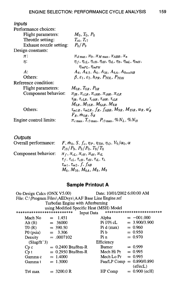
ENGINE SELECTION: PERFORMANCE CYCLE ANALYSIS 159
Inputs
Performance choices:
Flight parameters:
Throttle setting:
Exhaust nozzle setting:
Design constants:
rr:
r/:
A:
Others:
Reference condition:
Flight parameters:
Component behavior:
Others:
Engine control limits:
Mo, To, Po
Zt4, Tt7
P0/e9
T(dmax, 7~b, 7t'Mmax, T(ABR, 7g n
Of, tlcL, TIcH, T]tH, 17tL, Ob, TIroL, 17mH,
FImPL, OmPH
A4, A4.5, A6, A16,
A6A, A8wo/AB
fl, el, e2, hpR, ProL, Pron
MOR, TOR,
POR
7~fR, 712cLR~ 7rcHR, YgtHR, T(tLR
75fR, 75cLR, TcHR, TtHR, "gtLR
M6R, M16R, M6AR, MSR
rmlR, rm2R, fR, fABR, M9R, M19R, OtR, O{ R
FR, /nOR, SR
7(cmax, Tt3max,
Pt3max, %Nc, %NH
Outputs
Overall performance:
Component behavior:
F,/no, S, fo, rip, TITH, 110,
V9/Olo,
Pt9 / Pg, eg / Po, Tg / To
T( f , 7"(cL , YfcH~ 7[tH~ 2"l'tL
"t'f ~ TcL , "6cH , "CtH , "CtL ,
~l
rml, rm2,
f,
fAB
M6, M16,
M6A, M8, M9
Sample Printout A
On-Design Calcs (ONX V5.00) Date: 10/01/2002 6:00:00 AM
File: C:\Program Files\AEDsys\AAF Base Line Engine.ref
Turbofan Engine with Afterbuming
using Modified Specific Heat (MSH) Model
Mach No
Alt (ft)
TO (R)
P0 (psia)
Density
(Slug/ft^3)
Cp c
Cp t
Gamma c
Gamma t
Input Data
= 1.451 Alpha
= 36000 Pi f/Pi cL
= 390.50 Pi d (max) =
= 3.306 Pi b --
= .0007102 Pin =
Efficiency
= 0.2400 Btu/lbm-R Burner =
-- 0.2950 Btu/lbm-R Mech Hi Pr =
= 1.4000 Mech Lo Pr =
= 1.3000 Fan/LP Comp =
Tt4 max = 3200.0 R
= -001.000
= 3.900/3.900
0.960
0.950
0.970
HP Comp =
0.999
0.995
0.995
0.890/0.890
(ef/ecL)
0.900 (ecH)
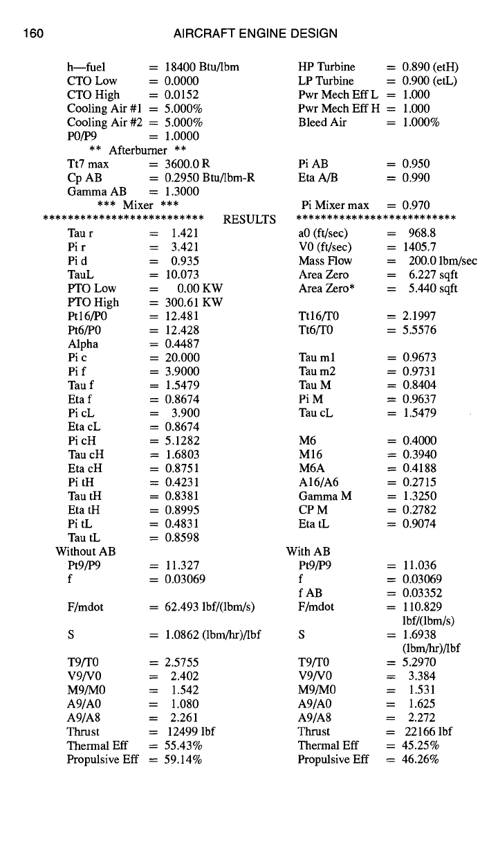
160 AIRCRAFT ENGINE DESIGN
h--fuel = 18400 Btu/lbm
CTO Low = 0.0000
CTO High = 0.0152
Cooling Air #1 = 5.000%
Cooling Air #2 = 5.000%
P0/P9 = 1.0000
** Afterburner **
Tt7 max = 3600.0 R
Cp AB = 0.2950 Btu/lbm-R
Gamma AB = 1.3000
*** Mixer ***
************************** RESULTS
liP Turbine = 0.890 (etH)
LP Turbine = 0.900 (etL)
Pwr Mech Elf L = 1.000
Pwr Mech Eft H = 1.000
Bleed Air = 1.000%
Pi AB = 0.950
Eta A/B = 0.990
Pi Mixer max = 0.970
**************************
Tau r = 1.421 a0 (ft/sec) = 968.8
Pi r = 3.421 V0 (ft/sec) = 1405.7
Pi d = 0.935 Mass Flow = 200.0 lbrn/sec
TauL = 10.073 Area Zero = 6.227 sqft
PTO Low = 0.00 KW Area Zero* = 5.440 sqft
PTO High = 300.61 KW
Ptl6/P0 = 12.481 Ttl6/T0 = 2.1997
Pt6/P0 = 12.428 Tt6/T0 = 5.5576
Alpha = 0.4487
Pi c = 20.000 Tau ml = 0.9673
Pi f = 3.9000 Tau m2 = 0.9731
Tau f = 1.5479 Tau M = 0.8404
Eta f = 0.8674 Pi M = 0.9637
Pi cL = 3.900 Tau cL = 1.5479
Eta cL = 0.8674
PicH = 5.1282 M6 = 0.4000
Tau cH = 1.6803 M16 = 0.3940
EtacH = 0.8751 M6A = 0.4188
PitH = 0.4231 A16/A6 = 0.2715
Tau tH = 0.8381 Gamma M = 1.3250
Eta tH = 0.8995 CP M = 0.2782
Pi tL = 0.4831 Eta tL = 0.9074
Tau tL = 0.8598
Without AB With AB
Pt9/P9 = 11.327 Pt9/P9 = 11.036
f = 0.03069 f = 0.03069
f AB = 0.03352
F/mdot = 62.493 lbf/(lbm/s) F/mdot = 110.829
lbf/(lbm/s)
S = 1.0862 (lbm/hr)/lbf S = 1.6938
(lbm/hr)/lbf
T9/T0 = 2.5755 T9/T0 = 5.2970
V9/V0 = 2.402 V9/V0 = 3.384
M9/M0 = 1.542 M9/M0 = 1.531
A9/A0 = 1.080 A9/A0 = 1.625
A9/A8 = 2.261 A9/A8 = 2.272
Thrust = 12499 lbf Thrust = 22166 lbf
Thermal Eff = 55.43% Thermal Eft = 45.25%
Propulsive Eft = 59.14% Propulsive Eft = 46.26%
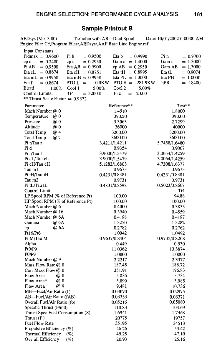
ENGINE SELECTION: PERFORMANCE CYCLE ANALYSIS 161
Sample Printout B
Turbofan with AB--Dual Spool AEDsys (Ver. 3.00)
Engine File: C:\Program Files\AEDsys\AAF Base Line Engine.ref
Date: 10/01/2002 6:00:00 AM
Input Constants
Pidmax = 0.9600 Pi b = 0.9500 Eta b = 0.9990
cp c = 0.2400 cp t = 0.2950 Gam c = 1.4000
Pi AB = 0.9500 Eta AB = 0.9900 cp AB = 0.2950
EtacL = 0.8674 EtacH = 0.8751 EtatH = 0.8995
Eta mL = 0.9950 Eta mH = 0.9950 Eta PL = 1.0000
Eta f = 0.8674 PTO L = 0.0KW PTO H = 281.9KW
Bleed = 1.00% Cool 1 = 5.00% Cool 2 = 5.00%
Control Limits: Tt4 ----- 3200.0 Pi c = 20.00
** Thrust Scale Factor = 0.9372
Parameter Reference**
Mach Number @ 0 1.4510
Temperature @ 0 390.50
Pressure @ 0 3.3063
Altitude @ 0 36000
Total Temp @ 4 3200.00
Total Temp @ 7 3600.00
Pi r/Tau r 3.4211/1.4211
Pi d 0.9354
Pi f/Tau f 3.9000/1.5479
Pi cL/Tau cL 3.9000/1.5479
Pi cH/Tau cH 5.1282/1.6803
Tau ml 0.9673
Pi tH/Tau tH 0.4231/0.8381
Tau m2 0.9731
Pi tL/Tau tL 0.4831/0.8598
Control Limit
LP Spool RPM (% of Reference Pt) 100.00
HP Spool RPM (% of Reference Pt) 100.00
Mach Number @ 6 0.4000
Mach Number @ 16 0.3940
Mach Number @ 6A 0.4188
Gamma @ 6A 1.3250
cp @ 6A 0.2782
Pt 16/Pt6 1.0042
Pi M/Tau M 0.9637/0.8404
Alpha 0.449
Pt9/P9 11.0362
P0/P9 1.0000
Mach Number @ 9 2.2217
Mass Flow Rate @ 0 187.45
Corr Mass Flow @ 0 251.91
Flow Area @ 0 5.836
Flow Area* @ 0 5.099
Flow Area @ 9 9.481
MB--Fuel/Air Ratio (f) 0.03070
AB--Fuel/Air Ratio (fAB) 0.03353
Overall Fuel/Air Ratio (fo) 0.05216
Specific Thrust (F/m0) 110.83
Thrust Spec Fuel Consumption (S) 1.6941
Thrust (F) 20775
Fuel Flow Rate 35195
Propulsive Efficiency (%) 46.26
Thermal Efficiency (%) 45.25
Overall Efficiency (%) 20.93
Pin = 0.9700
Gam t = 1.3000
Gam AB = 1.3000
Eta tL = 0.9074
Eta PH = 1.0000
hPR = 18400
Test**
1.8000
390.00
2.7299
40000
3200.00
3600.00
5.7458/1.6480
0.9067
3.0054/1.4259
3.0054/1.4259
4.7208/1.6377
0.9673
0.4231/0.8381
0.9731
0.5023/0.8667
Tt4
94.88
100.00
0.3835
0.4559
0.4187
1.3282
0.2762
1.0492
0.9735/0.8268
0.530
13.3874
1.0000
2.3377
188.72
196.83
5.734
3.985
10.736
0.02975
0.03371
0.05080
104.69
1.7468
19757
34513
53.42
47.10
25.16