Mattingly J.D., Heiser W.H., Pratt D.T. Aircraft Engine Design
Подождите немного. Документ загружается.

ENGINE SELECTION: PARAMETRIC CYCLE ANALYSIS 121
These numbers will also be useful in the initial estimation of
Pro Pro F
Cro -- rhoho Fho rho
(4.33)
4.3.3 Parametric vs Performance Behavior
During this process of selecting a set of reference point parameters for each
critical flight condition, it is important to remember that the final engine will always
be running off-design and will therefore behave differently at each operating point.
Thus, it makes little sense to try to find an engine, for example, of
fixed rrc, try,
or, and
Zt4
that works reasonably well at every operating point. It is, however,
desirable to have the selected sets of reference point parameters generally follow
the natural path of a single engine running off-design. Applying this logic will
increase the probability of success of a design.
But how is this natural path established in advance? There is no simple answer
to this question, but some good approximations are available. The best would
be to run several off-design computations (see Chapter 5) for promising designs
in order to generate directly applicable guidance. This would be equivalent to
coupling parametric and performance computations in an iterative manner and,
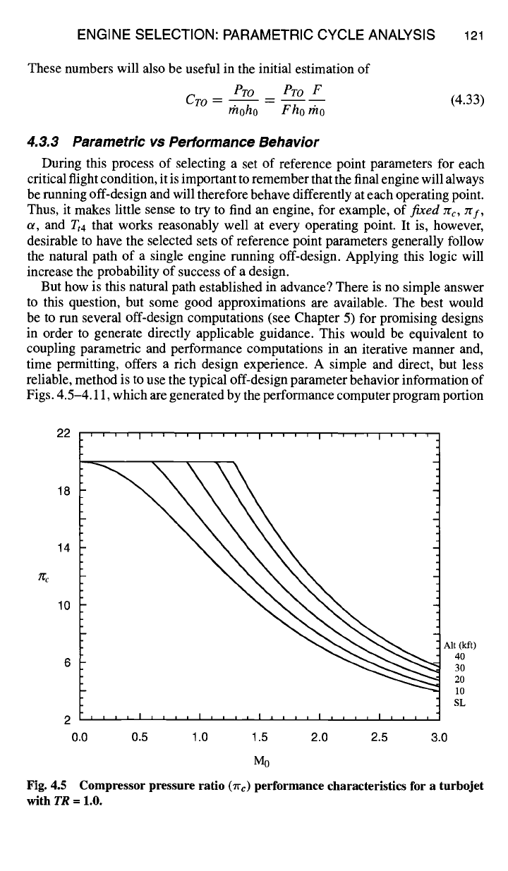
time permitting, offers a rich design experience. A simple and direct, but less
reliable, method is to use the typical off-design parameter behavior information of
Figs. 4.5-4.11, which are generated by the performance computer program portion
22
18
14
10
6
' ' ' ' I ' ' ' ' I '
0.0 0.5 1.0
' ' ' I ' ' ' ' I ' ' ' ' I ' ' ' '
X
\
\
\
' ' ' I I I i I i I I I I
[
I i I I
1.5 2.0 2.5 3.0
Mo
Aft (kft)
40
30
20
I0
SL
Fig. 4.5 Compressor pressure ratio (~'c) performance characteristics for a turbojet
with
TR =
1.0.
22 ''''l''''l''''l''''l
14
18
\
\
\
10
Air (kft)
40
30
20
10
SL
2
, , J = I , , = = I ~ , , , i .... i ....
0.0 0.5 1.0 1.5 2.0 2.5
Mo
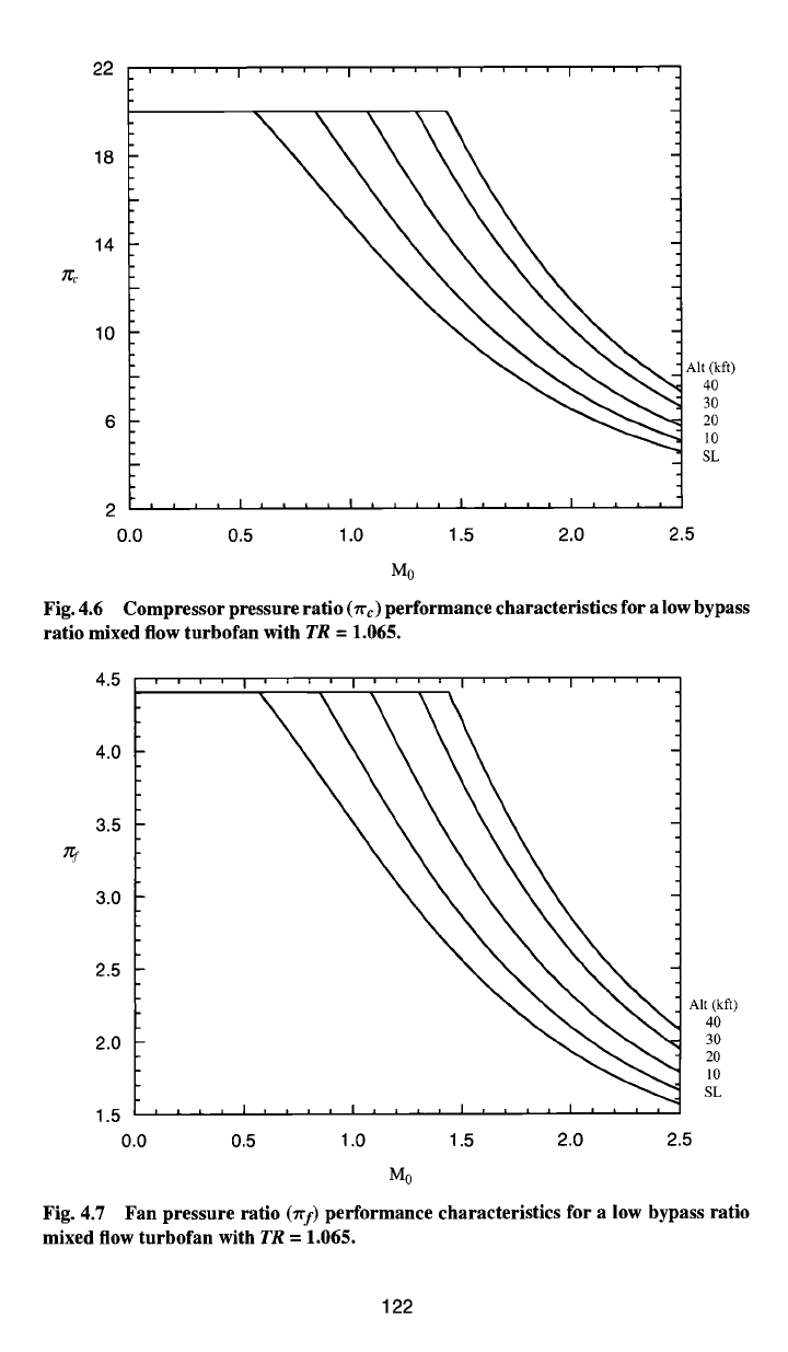
Fig. 4.6 Compressor pressure ratio (Trc) performance characteristics for a low bypass
ratio mixed flow turbofan with TR = 1.065.
4.5
I''''1''''1'
4.0
3.5
3.0
2.5
2.0
I '
Alt (kft)
40
30
20
10
SL
1.5 i i , I , , , , I , , , , I , , , , I , ~ , ,
0.0 0.5 1.0 1.5 2.0 2.5
Mo
Fig. 4.7 Fan pressure ratio
('/l'f)
performance characteristics for a low bypass ratio
mixed flow turbofan with TR = 1.065.
122
1.1
I , , , , I , i , , I ' ' ' ,
Alt (kft)
SL
10
20
1.0
0.9
30
40
0.8
a
0.7
0.6
0.5 .... I ~ , , , I , , ~ , I , , , , I , , , ,
0.0 0.5 1.0 1.5 2.0 2.5
Mo
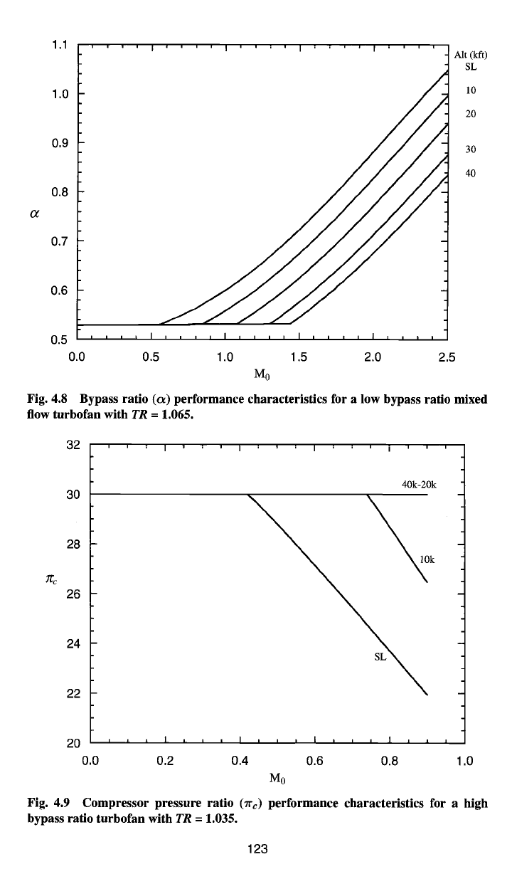
Fig. 4.8
Bypass ratio (c~) performance characteristics for a low bypass ratio mixed
flow turbofan with
TR =
1.065.
32
' I ' I
30
28
26
24
22
I I
40k-20k
~O]Ok
20
, , , I , , , I , , , I , , , I , , ,
0.0 0.2 0.4 0.6 0.8 1.0
Mo
Fig. 4.9 Compressor pressure ratio (Trc) performance characteristics for a high
bypass ratio turbofan with
TR =
1.035.
123
:~l J 120k.40 k
1.52
1.50
1.48
1.46
1.44
1.42
1.40
1.38
rq
1.36 ,
, , I , , , I , , , I , , , I , L ,
0.0 0.2 0.4 0.6 0.8 1.0
Mo
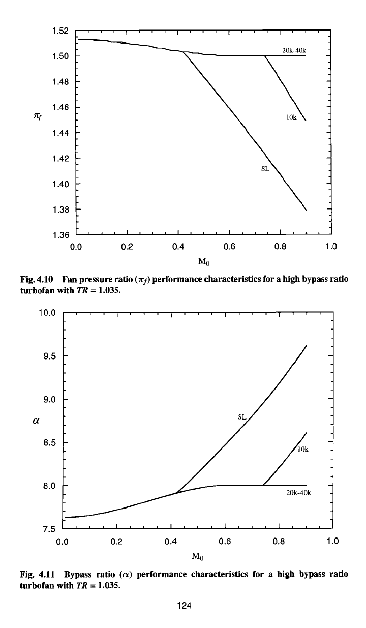
Fig. 4.10 Fan pressure ratio
(Tif)
performance characteristics for a high bypass ratio
turbofan with TR = 1.035.
10.0
I ' I I I '
9.0
a s
8.0
20k-40k
7.5 , i , , , i , , , l , , , I , , ,
0.0 0.2 0.4 0.6 0.8 1.0
Mo
Fig.
4.11 Bypass ratio (c~)
performance characteristics for a high bypass ratio
turbofan with TR = 1.035.
124
ENGINE SELECTION: PARAMETRIC CYCLE ANALYSIS 125
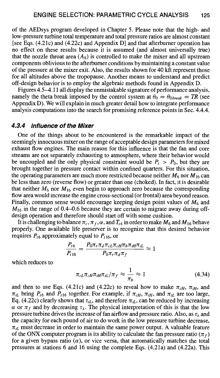
of the AEDsys program developed in Chapter 5. Please note that the high- and
low-pressure turbine total temperature and total pressure ratios are almost constant
[see Eqs. (4.21c) and (4.22c) and Appendix D] and that afterburner operation has
no effect on these results because it is assumed (and almost universally true)
that the nozzle throat area (As) is controlled to make the mixer and all upstream
components oblivious to the afterburner conditions by maintaining a constant value
of the pressure at the mixer exit. Also, the results shown for 40 kft represent those
for all altitudes above the tropopause. Another means to understand and predict
off-design behavior is to employ the algebraic methods found in Appendix D.
Figures 4.5-4.11 all display the unmistakable signature of performance analysis,
namely the theta break imposed by the control system at 00 =
Oooreak = TR
(see
Appendix D). We will explain in much greater detail how to integrate performance
analysis computations into the search for promising reference points in Sec. 4.4.4.
4.3.4 Influence of the Mixer
One of the things about to be encountered is the remarkable impact of the
seemingly innocuous mixer on the range of acceptable design parameters for mixed
exhaust flow engines. The main reason for this influence is that the fan and core
streams are not separately exhausting to atmosphere, where their behavior would
be uncoupled and the only physical constraint would be
Pt > Po,
but they are
brought together in pressure contact within confined quarters. For this situation,
the operating parameters are much more restricted because neither M6 nor M16 can
be less than zero (reverse flow) or greater than one (choked). In tact, it is desirable
that neither M6 nor M16 even begin to approach zero because the corresponding
flow area would increase the engine cross-sectional (or frontal) area beyond reason.
Finally, common sense would encourage keeping design point values of M6 and
MI6 in the range of 0.4-0.6 because they are certain to migrate away during off-
design operation and therefore should start off with some cushion.
It is challenging to balance rrc, try, or, and
Tt4
in order to make M6 and M16 behave
properly. One available life preserver is to recognize that this desired behavior
requires
Pt6
approximately equal to
Ptl6,
or
Pt6 Po~rT"fdYfcLYrcHYrbYrtHrftL
Ptl6 POTfr~dTg f
which reduces to
1
7licLJ~'c.HJ'gtHJ'CtL/Yr f
~ -- ~'~
1 (4.34)
7rb
and then to use Eqs. (4.21c) and (4.22c) to reveal how to make yrc~/, Yrtn, and
ZrtL bring
Pt6
and
Ptl6
together. For example, if Zrc~/, zra4, and
ZrtL are
too large,
Eq. (4.22c) clearly shows that rtL, and therefore rrtL, Can be reduced by increasing
o/or ygf and by decreasing rx. The physical interpretation of this is that the low
pressure turbine drives the increase of fan airflow and pressure ratio. Also, as rx and
the capacity for each pound of air to do work in the low pressure turbine decrease,
zrtL must decrease in order to maintain the same power output. A valuable feature
of the ONX computer program is its ability to calculate the fan pressure ratio (7rf)
for a given bypass ratio (or), or Vice versa, that automatically matches the total
pressures at stations 6 and 16 using the complete Eqs. (4.21a) and (4.22a). This
126 AIRCRAFT ENGINE DESIGN
feature is activated by following the directions at the bottom of the ONX input
data window for the mixed flow turbofan engine.
The final safety net is that the ONX computer program has been arranged to
override the input of M6 if M16 is out of limits in order to obtain a legitimate
solution. Even if the solution is not a useful one (i.e., M16 "~ 0), the results will
indicate the right direction. If no solution is possible, the printout will tell which
of the two mixer entry total pressures was too high.
4.3.5 The Good News
Applying the ONX parametric engine cycle computer program to a new set of
requirements is an exhilarating experience. The tedious work is done so swiftly and
the results are so comprehensive that natural curiosity simply takes over. Almost
any search procedure from almost any starting point quickly leads to the region
of most promising results. The influence of any single input parameter on all of
the output quantities can be immediately determined by changing its value only
slightly. This is the basis of sensitivity analysis (see Sec. 4.4.5). The behavior of
each component can also be clearly traced and the possibility of exceeding some
design limitation (e.g., compression ratio or temperature) easily avoided.
In addition to fun, there is also learning. Armed with computational power and
an open mind, the best solutions made possible by natural laws literally make
themselves known. Simultaneously, the payoff made possible by various tech-
nological improvements or changes in the ground rules is determined. For the
moment, each participant really is like an engine company preliminary design
group, with similar capabilities and limitations. No wonder it is exhilarating.
4.4 Example Engine Selection: Parametric Cycle Analysis
Using the methods of the preceding sections, the search begins for the best com-
binations of engine design parameters for the Air-to-Air Fighter (AAF) described
in the Request for Proposal (RFP) of Chapter 1. Of the three thermodynamic mod-
els available with the ONX program, we have chosen to use for this exercise the
modified specific heat model MSH (constant specific heats through all components
except the combustor and afterburner where variable specific heats give a more
accurate estimate of the fuel consumption). This engine model gives the best of
both worlds--quick and accurate estimates of engine parametric behavior. Possi-
ble combinations of engine design points at selected critical flight conditions will
be investigated in order to narrow the ranges of key engine design parameters.
Once the most promising ranges of these parameters have been found, off-design
or performance analysis (Chapter 5) can proceed and the selected engine sized
(Chapter 6) to produce the installed thrust required.
4.4.1 Selection of Suitable Ranges of Design Point Parameters
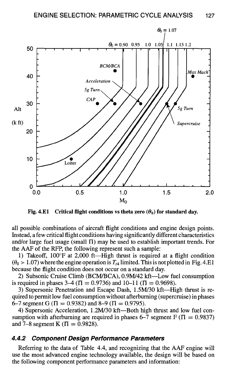
In the constraint analysis of Chapter 2, a preliminary choice was made of the
engine's throttle ratio
(TR),
and a value of 1.07 was selected. The AAF constraint
and mission flight conditions are plotted vs theta zero (00) in Fig. 4.El. Note that
the corresponding flight conditions bracket the 1.07 value of 00. The engine is
Tt4
limited to the right of 00 = 1.07 and zrc limited to the left (see Appendix D).
To shrink the bewilderingly large number of promising reference point choices
to a manageable size, it is not necessary to conduct an exhaustive investigation of
ENGINE SELECTION: PARAMETRIC CYCLE ANALYSIS
190 = 1.07
50
127
40
Alt
(k ft)
30
20
10
0
0.0 0.5 1.0 1.5 2.0
M0
Critical flight conditions
vs theta
zero (00)
for standard
day.
Fig. 4.El
all possible combinations of aircraft flight conditions and engine design points.
Instead, a few critical flight conditions having significantly different characteristics
and/or large fuel usage (small FI) may be used to establish important trends. For
the AAF of the RFP, the following represent such a sample:
1) Takeoff, 100°F at 2,000 ft--High thrust is required at a flight condition
(00 > 1.07) where the engine operation is
Tt4
limited. This is not plotted in Fig. 4.E 1
because the flight condition does not occur on a standard day.
2) Subsonic Cruise Climb (BCM/BCA), 0.9M/42 kftiLow fuel consumption
is required in phases 3-4 (I-I = 0.9736) and 10-11 (FI = 0.9698).
3) Supersonic Penetration and Escape Dash, 1.5M/30 kft--High thrust is re-
quired to permit low fuel consumption without afterburning (supercruise) in phases
6-7 segment G (FI = 0.9382) and 8-9 (FI = 0.9795).
4) Supersonic Acceleration, 1.2M/30 kftiBoth high thrust and low fuel con-
sumption with afterburning are required in phases 6-7 segment F (FI = 0.9837)
and 7-8 segment K (FI = 0.9828).
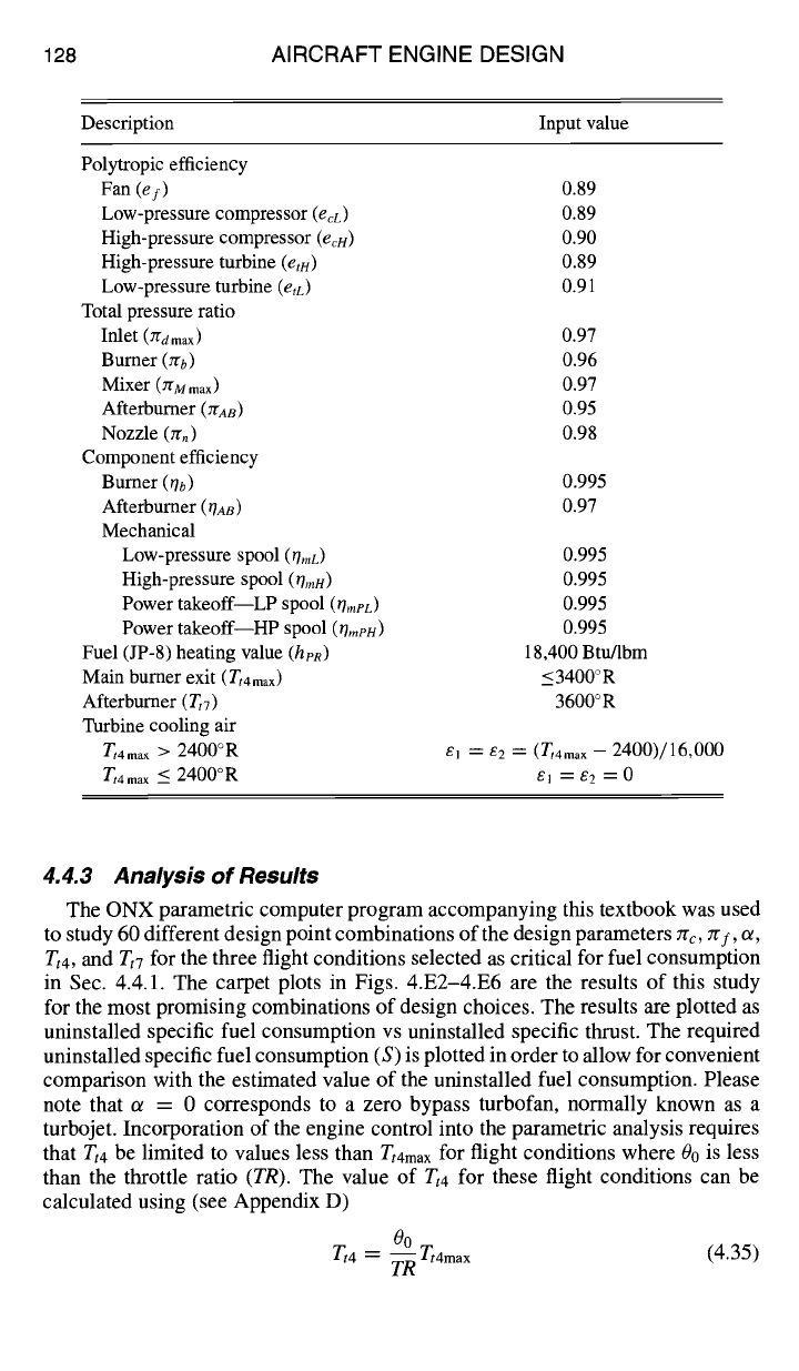
4.4.2 Component Design Performance Parameters
Referring to the data of Table 4.4, and recognizing that the AAF engine will
use the most advanced engine technology available, the design will be based on
the following component performance parameters and information:
128 AIRCRAFT ENGINE DESIGN
Description Input value
Polytropic efficiency
Fan
(ef)
0.89
Low-pressure compressor
(eeL)
0.89
High-pressure compressor (ecu) 0.90
High-pressure turbine (etH) 0.89
Low-pressure turbine (etD 0.91
Total pressure ratio
Inlet (Ygd max) 0.97
Burner (zrb) 0.96
Mixer (ZrM
max)
0.97
Afterburner (ZrAB) 0.95
Nozzle (zrn) 0.98
Component efficiency
Burner
(Ob)
0.995
Afterburner 0/AS) 0.97
Mechanical
Low-pressure spool
(OmL)
0.995
High-pressure spool (0m/4) 0.995
Power takeoff LP spool
(l]meL)
0.995
Power takeoff HP spool
(tlmeu)
0.995
Fuel (JP-8) heating value
(heR)
18,400 Btu/lbm
Main burner exit (Tt4
max )
_~< 3400 ° R
Afterburner (TtT) 3600°R
Turbine cooling air
Tt4max > 2400°R 61 = 62 = (Tt4max - 2400)/16,000
Tt4max
~-~ 2400°R sl = 62 = 0
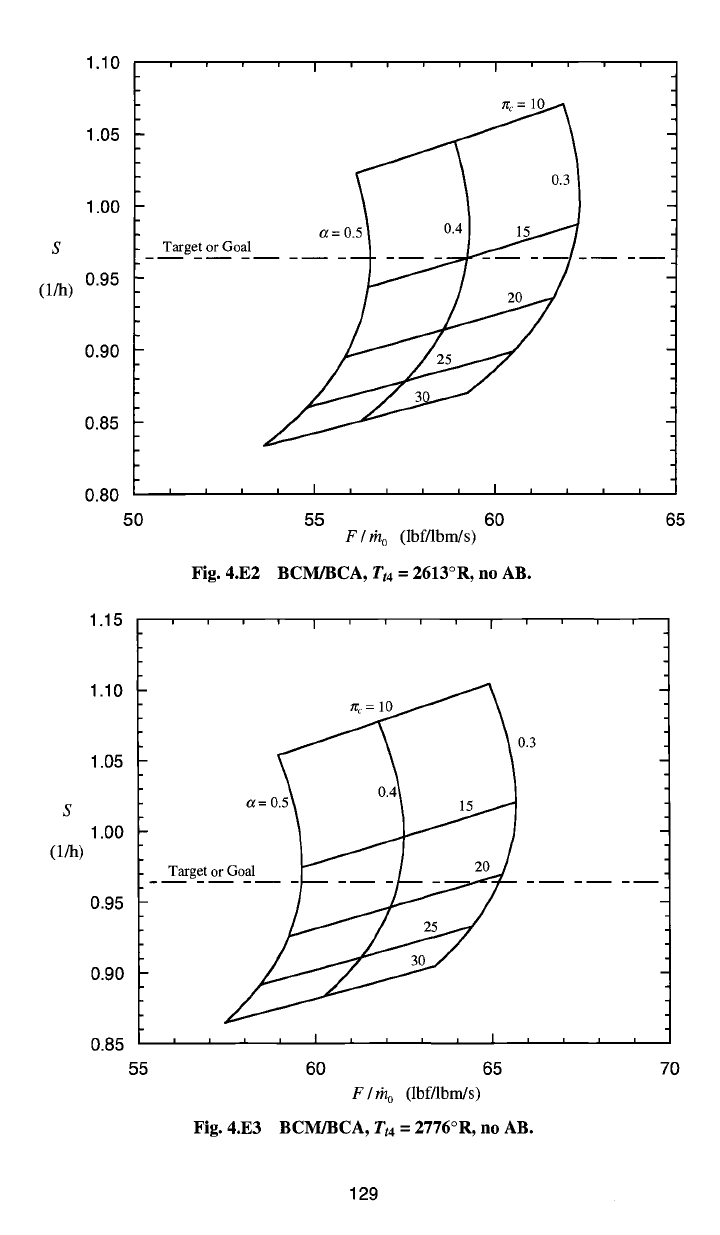
4.4.3 Analysis of Results
The ONX parametric computer program accompanying this textbook was used
to study 60 different design point combinations of the design parameters Zrc, zrf, or,
Tt4, and Tt7 for the three flight conditions selected as critical for fuel consumption
in Sec. 4.4.1. The carpet plots in Figs. 4.E2-4.E6 are the results of this study
for the most promising combinations of design choices. The results are plotted as
uninstalled specific fuel consumption vs uninstalled specific thrust. The required
uninstalled specific fuel consumption (S) is plotted in order to allow for convenient
comparison with the estimated value of the uninstalled fuel consumption. Please
note that ~ = 0 corresponds to a zero bypass turbofan, normally known as a
turbojet. Incorporation of the engine control into the parametric analysis requires
that
Tt4
be limited to values less than
Tt4ma x
for flight conditions where 00 is less
than the throttle ratio
(TR).
The value of
Tt4
for these flight conditions can be
calculated using (see Appendix D)
00 ,~ "max
(4.35)
Zt4 = ~1,4
S
(i/h)
1.10
1.05
1.00
0.95
0.90
0.85
0.80
Target or Goal
I I I
5O
Fig.
4.E2
I ' I
°=05 t
/_
, I , , , , I ,
55 60
F / rh o
(Ibf/lbm/s)
BCM/BCA,
Tt4
= 2613°R, no AB.
1.15
1.10
1.05
E
1.00
(l/h)
0.95
0.90
0.85
55
' I ' ' I '
~
0.3
, , , , I , , , , I ,
60 65
F / rh o
(lbf/lbm/s)
Fig. 4.E3 BCM/BCA,
Tt4
= 2776°R, no AB.
65
70
129
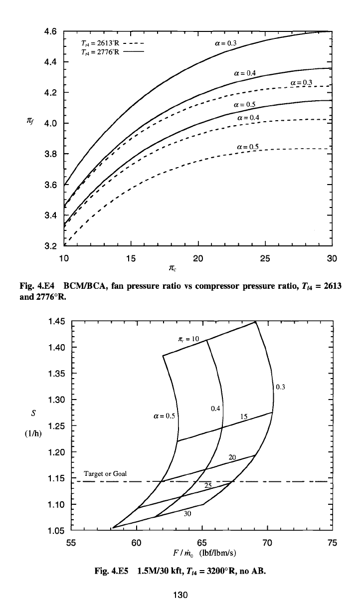
4.6
4.4
4.2
4.0
3.8
3.6
3.4
3.2
Tt4 = 2613°R ....
Tt4 = 2776°R --
a=0.3
r S
J
S
S
S
J a=0.4 o~= 0.3
- ~ o~= 0.4
~ ~ a=0.5
..........
10 15 20 25 30
zcc
Fig. 4.E4 BCM/BCA, fan pressure ratio vs compressor pressure ratio,
Tt4
-- 2613
and 2776°R.
S
(l/h)
1.45
1.40
1.35
1.30
1.25
1.20
1.15
1.10
1.05
55
' ' ' ' I ' ' ' ' I ' ' ~ I '
a=~ 0"3
, , , ,z~,, , ,~~-
~.°
, .... , ,
60 65 70
F / rh o
(lbf/lbm/s)
Fig. 4.E5 1.5M/30 kft,
Tt4
=
3200°R, no AB.
I I I
75
130