Mattingly J.D., Heiser W.H., Pratt D.T. Aircraft Engine Design
Подождите немного. Документ загружается.

ENGINE SELECTION: PARAMETRIC CYCLE ANALYSIS 101
of Secs. 4.2.3 and 4.2.4, and then mark their location carefully so that you can find
them quickly whenever necessary.
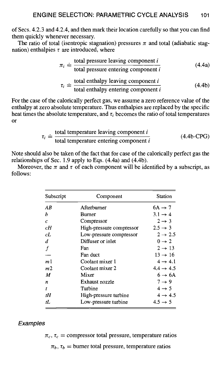
The ratio of total (isentropic stagnation) pressures rr and total (adiabatic stag-
nation) enthalpies r are introduced, where
total pressure leaving component i
zri -- (4.4a)
total pressure entering component i
total enthalpy leaving component i
ri -- (4.4b)
total enthalpy entering component i
For the case of the calorically perfect gas, we assume a zero reference value of the
enthalpy at zero absolute temperature. Thus enthalpies are replaced by the specific
heat times the absolute temperature, and ri becomes the ratio of total temperatures
or
total temperature leaving component i
vi - (4.4b-CPG)
total temperature entering component i
Note should also be taken of the fact that for case of the calorically perfect gas the
relationships of Sec. 1.9 apply to Eqs. (4.4a) and (4.4b).
Moreover, the Jr and v of each component will be identified by a subscript, as
follows:
Subscript Component Station
AB
Afterburner 6A --~ 7
b Burner 3.1 --~ 4
c Compressor 2 ~ 3
cH
High-pressure compressor 2.5 ~ 3
cL
Low-pressure compressor 2 ~ 2.5
d Diffuser or inlet 0 --~ 2
f Fan 2 ~ 13
-- Fan duct 13 --~ 16
m 1 Coolant mixer 1 4 --~ 4.1
m2 Coolant mixer 2 4.4 ~ 4.5
M Mixer 6 -~ 6A
n Exhaust nozzle 7 ~ 9
t Turbine 4 ~ 5
tH
High-pressure turbine 4 --+ 4.5
tL
Low-pressure turbine 4.5 ~ 5
Examples
zrc, rc = compressor total pressure, temperature ratios
zrb, rb = burner total pressure, temperature ratios

102 AIRCRAFT ENGINE DESIGN
Exception. rr and Err are related to adiabatic and isentropic freestream re-
covery, respectively, and are defined by
h,o ho + V~/(2&)
rr "-- -- (4.5a)
ho ho
['to Prto
Er r ~'
-- -- (4.55)
Po go
Thus, freestream total enthalpy hto = horr and freestream total pressure Pro =
Po Err. For the simplifying case of a calorically perfect gas, we have, in accordance
with Sec. 1.9,
rto
v 1
- 1 q- c-=---M~ (4.5a-CPG)
Tr -- TO
Z v
( Y-1 2) ~'--~
Err = Tr r-I =
1 + ----~M;
(4.5b-CPG)
Further exceptions.
It is often desirable to work in terms of design limitations
such as the maximum allowable turbine inlet total temperature, Tt4. The term rx
is thus used and is defined in terms of the enthalpy ratio
ht4
rx -- -- (4.6c)
h0
Similarly, for the afterburner
ht7
r),aB --" -- (4.6d)
h0
For a calorically perfect gas, Eqs. (4.6c) and (4.6d) become
r)~- Cp4Tt4
(4.6c-CPG)
C po To
C p7 Tt7
r)~AB --
(4.6d-CPG)
C po To
Component Er and
r. A complete compilation of total pressure and total
enthalpy ratios follow. Please note in the following that it has been assumed that
Ptl3 = Ptl6, ht13 = htl6
and Pt3 =
Pt3.1, hi3 = ht3.1.
Diffuser (includes ram recovery):
Fan:
Pt2 ht2
Erd = -- rd -- -- 1 (4.7a)
Pro hto
Ptl3
ht13
Erf
=
Pt2 "~f = ht2 (4.7b)
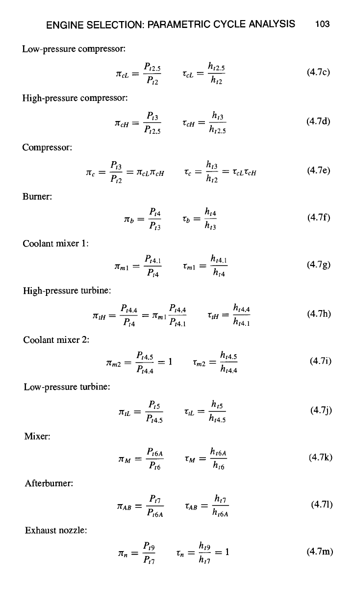
ENGINE SELECTION: PARAMETRIC CYCLE ANALYSIS 103
Low-pressure compressor:
7~cL ~.
et2.5 ht2.5
75cL
P,2 ht2
High-pressure compressor:
2"fcH :
Pt3 ht3
V:cH
Pt2.5 ht2.5
Compressor:
et3
7g c ~- -- ~__ 7~cLYgcH
P,2
~c --
ht3
-- "CcL TcH
ht2
Burner:
et4 hi4
7~b = -- "Cb --
et3 ht3
Coolant mixer 1:
Pt4.1
7"t'ml = ~'ml --
/',4
ht4.1
ht4
High-pressure turbine:
~tH -- --
et4.4 et4.4
-- ~ml--
P,4 Pt4.1
"ftH
ht4.4
ht4.1
Coolant mixer 2:
~m2 -- --
Pt4.5
et4.4
--1
ht4.5
"Cm2 -
ht4.4
Low-pressure turbine:
YrtL =
1'15
Pt4.5
"~tL
ht5
ht4.5
Mixer:
~M
Pt6A
e,6
ht6A
• M --
ht6
Afterburner:
Pt7
2"gAB _
Pt6A
ht7
~AB--
ht6A
Exhaust nozzle:
Pt9
P~7
ht9
-1
ht7
(4.7c)
(4.7d)
(4.7e)
(4.7f)
(4.7g)
(4.7h)
(4.7i)
(4.7j)
(4.7k)
(4.71)
Jr. -- rn -- (4.7m)

104 AIRCRAFT ENGINE DESIGN
For the calorically perfect gas, all of the component r except that of the burner
and afterbumer become total temperature ratios. For example, rc = Tt3/Tt2 and
rtH
= Tt4.n/Tt4.1.
The r for the bumer and afterburner become
C p4 Tt 4
-gb -- (4.7f-CPG)
C p3 Tt3
"gAB-- cp7Tt7 (4.71-CPG)
Cp6A Tt6A
4.2.4 Mass Flow Rates
The mixed-flow turbofan engine with afterbuming, bleed air, and cooling air
is a very complex machine with numerous air and fuel flow rates. The cycle
analysis of this engine includes those mass flow rates that have major importance
in engine performance and, hence, cycle selection. Please note that the mass flow
rate frequently changes between stations as flow is added or removed or fuel is
added (see Fig. 4.2). The symbol rh is used for the mass flow rate with a subscript
to denote the type as follows:
Subscript Description Station
b
C
cl
c2
F
f
fAB
0--+9
Bleed air 3-3.1
Core airflow through engine 2.5, 3
Cooling air for high-pressure turbine nozzle vane 3-3.1, 4-4.1
Cooling air for remainder of high-pressure turbine 3-3.1, 4.1-4.4
Fan air flow through bypass duct 13, 16
Fuel flow to main burner 3.1-4
Fuel flow to afterbumer 6A-7
Flow rate at numbered station
Mass flow ratios. In engine cycle analysis, it is often most effective to cast
the calculations into dimensionless mass flow ratios. The most useful of these for
the engine of Figs. 4.1 a, 4. lb, and 4.2 include the following:
Bypass ratio (or):
Bleed air fraction (fl):
bypass flow rh F
Ct --' -- (4.8a)
core flow rhc
Cooling air fractions (el and e2):
El-
bleed flow rhb
core flow rhc
82 ~"
(4.8b)
mcooll (4.8c)
rhc
rhc°°12 (4.8d)
rhc
ENGINE SELECTION: PARAMETRIC CYCLE ANALYSIS lO5
t • thcfl rhc¢ 2 •
mcEl b.
rhc(fl +el +~ 2 )
rhI[ v~
3.1 • 4 41 high-p ....... turbine 4i4 ,
25~31
,~--~,~--~,~-~ ~----~,~
' i b=:l I iEI I r:= ] I :
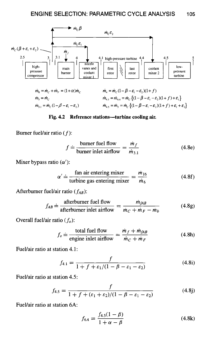
rho=rhc+fh ~ = (l+a)rh c
r~= rh c
~, =mc(1-fl-e,-e2)
m 4 = thc(1- fl -ei -e2)(l+ f)
th4. , = rh4. , = rh c {(1 -/3 -e, - e2)(1 + f)
+e,}
m45 =ms = rhc {(1-fl -e,-e2)(1+ f)+e, +e:}
Fig. 4.2 Reference stations--turbine cooling air.
Burner fuel/air ratio (f):
burner fuel flow
/'hf
f-
burner
inlet airflow rh3.1
Mixer bypass ratio (a'):
o/I --
fan air entering mixer rh 16
turbine gas entering mixer
/'h 6
Afterburner fuel/air ratio (faB):
fAB --"
afterburner fuel flow
rhfAB
afterburner inlet airflow rhc + rhF -- rhb
Overall fuel/air ratio (fo):
fo-
total fuel flow
#if -Jv rhfAB
engine inlet airflow thc ~-
?/'/F
Fuel/air ratio at station 4.1:
f4.1=
f
1-I-f-t-el/(1
--f--E 1 --82)
Fuel/air ratio at station 4.5:
f4.5
f
l+f-k-(el -k-e2)/(1 --~--E 1 --S2)
Fuel/air ratio at station 6A:
f6A --
f4"5(1 -- /~)
l+ot-fl
(4.8e)
(4.8f)
(4.8g)
(4.8h)
(4.8i)
(4.8j)
(4.8k)
106 AIRCRAFT ENGINE DESIGN
Turbine cooling.
The model of turbine cooling incorporated into the engine
analysis is shown in Fig. 4.2. Cooling air is drawn off at the compressor exit
(station 3). A portion of this cooling air
(rhcoon = rhcei)
is used to cool the high-
pressure turbine nozzle guide vanes. The remainder
(rhcool2 = rhce2)
is used to
cool the high-pressure turbine rotor. For cycle purposes, the cooling airflows
mcooll
and rh~oot2 are modeled as being introduced and fully mixed in coolant mixer 1
and coolant mixer 2, respectively. No total pressure loss is assumed for coolant
mixer 2. No cooling air is included for the low-pressure turbine.
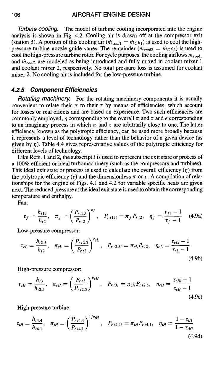
4.2.5 Component Efficiencies
Rotating machinery.
For the rotating machinery components it is usually
convenient to relate their Jr to their r by means of efficiencies, which account
for losses or real effects and are based on experience. Two such efficiencies are
commonly employed, r/corresponding to the overall Jr and r and e corresponding
to an imaginary process in which zr and r are arbitrarily close to one. The latter
efficiency, known as the polytropic efficiency, can be used more broadly because
it represents a level of technology rather than the behavior of a given device (as
given by 0). Table 4.4 gives representative values of the polytropic efficiency for
different levels of technology.
Like Refs. 1 and 2, the subscript i is used to represent the exit state or process of
a 100% efficient or ideal turbomachinery (such as the compressors and turbines).
This ideal exit state or process is used to calculate the overall efficiency (~) from
the polytropic efficiency (e) and the dimensionless zr or 3. A compilation of rela-
tionships for the engine of Figs. 4.1 and 4.2 for variable specific heats are given
next. The reduced pressure at the ideal exit state is used to obtain the corresponding
temperature and enthalpy.
Fan:
ht13
~f=(Prtl3~ ef
"Of
=
hi2 ' \ Prt2 J '
Low-pressure compressor:
ht2.5 ( ert2.5"~ ecL
rcL- ht2 7rcL ~, Pr,2 ,]
High-pressure compressor:
ht3 ( Prt3 ~ ecH
rd-1- ht2.5 , JrcH = \ P---~t2.5 / '
High-pressure turbine:
ht4.4 ( Prt4.4 ) 1/etH '
rtH - ht4.1' YrtH = ~ P~lt4.1,]
rfi -- 1
Prtl3i = 7gfPrt2,
Of -- --
(4.9a)
rf--1
ert2.5i ~- 7gcLert2, T]cL -- --
"EcL i -- 1
VcL- 1
(4.9b)
ert3i ~-- 7gcHert2.5, l']cH --
ZcHi -- 1
VcH-- 1
(4.9c)
Prt4.4i ~ 7gtHPrt4.1, TltH -- --
I -- TtH
1--rtni
(4.9d)
ENGINE SELECTION: PARAMETRIC CYCLE ANALYSIS lO7
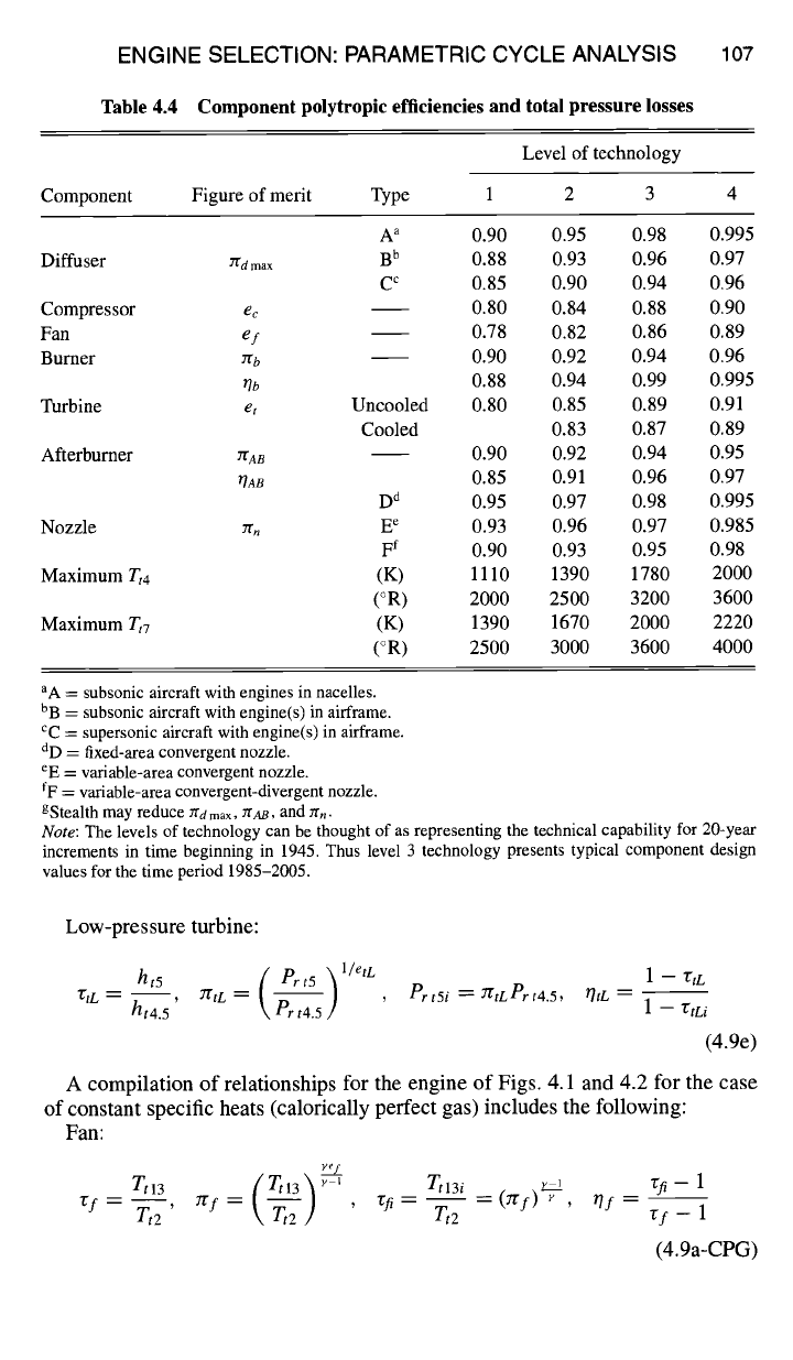
Table 4.4 Component polytropic efficiencies and total pressure losses
Component
Level of technology
Figure of merit Type 1 2 3 4
Diffuser
Compressor
Fan
Burner
Turbine
Afterburner
Nozzle
Maximum
Tt4
Maximum Tt 7
A a 0.90
rrd max B b 0.88
C c 0.85
ec
0.80
ef
0.78
rrb 0.90
r/b 0.88
et
Uncooled 0.80
Cooled
~AB
r/AB
7fn
0.90
0.85
D d 0.95
E e 0.93
F f O.9O
(K) 1110
(°R) 2000
(K) 1390
(°R) 2500
0.95 0.98 0.995
0.93 0.96 0.97
0.90 0.94 0.96
0.84 0.88 0.90
0.82 0.86 0.89
0.92 0.94 0.96
0.94 0.99 0.995
0.85 0.89 0.91
0.83 0.87 0.89
0.92 0.94 0.95
0.91 0.96 0.97
0.97 0.98 0.995
0.96 0.97 0.985
0.93 0.95 0.98
1390 1780 2000
2500 3200 3600
1670 2000 2220
3000 3600 4000
aA = subsonic aircraft with engines in nacelles.
bB = subsonic aircraft with engine(s) in airframe.
cC = supersonic aircraft with engine(s) in airframe.
dD
=
fixed-area convergent nozzle.
eE =
variable-area convergent nozzle.
fF =
variable-area convergent-divergent nozzle.
gStealth may reduce Jrd max, 7rAB, and zrn.
Note:
The levels of technology can be thought of as representing the technical capability for 20-year
increments in time beginning in 1945. Thus level 3 technology presents typical component design
values for the time period 1985-2005.
Low-pressure turbine:
ht5 ( Prr5 ] t/etL
1--rtL
r/tL -- ht4.5' 7ftL = ~Prt4.5J , Prt5i -D- 7rtLPrt4.5, rhL -- 1 -- rtLi
(4.9e)
A compilation of relationships for the engine of Figs. 4.1 and 4.2 for the case
of constant specific heats (calorically perfect gas) includes the following:
Fan:
yes
( __
Ttl3
Jrf = rtl3 y t rtl3i -- (j~I)'T- ~f =
"Of -- Tt2 ' \-~t2 ,] , "rfi -- Tt2 ' r f - 1
(4.9a-CPG)

108 AIRCRAFT ENGINE DESIGN
Low-pressure compressor:
yecL
Tt2.5
{
rt2.5
"~ Y -1 Tt2.5 i ~,-I
"(cLi -- 1
, = ! I - -- - (ZrcL) 7-, ~d. --
rcL -- Zt2 7t'cL ~-~t2 /] ' "CcLi Tt2 "gcL -- 1
High-pressure compressor:
(4.9b-CPG)
Tt3 ( rt3 ~ ~,-1 Zt3 i ×-1 "VcH i --1
= , = ----(JrcH) 7, 0cH=--
"EcH
Tt2.5
7gcH
Ik Tt2.5 /I
, "gcHi
Tt2.5 rcH
--
1
High-pressure turbine:
(4.9c-CPG)
y
Zt4.4 ( Tt4.4 ~ (Y-iSetH
Zt4.4i ~-,
1 -
rtH
,
---(n',H) 7, n~//- ~
"CtH
--
Tt4.1
~t, : Ik ~ ] , ~tHi
T,4.1
_ "Etni
(4.9d-CPG)
Low-pressure turbine:
rt5 (rls~(Y-~)etL
7:tL- Zt4. % , TCtL
=
~ T--~4.5/] '
Tt5i Lz2
1
-- "(tL
"gtLi
-- --
(2"gtL) Y
,
?]tL
-- --
Tt4.5 1 -- "gtLi
(4.9e-CPG)
Combustion components.
For those components in which combustion takes
place, combustion efficiency is used to characterize the degree to which the chem-
ical reactions have gone to completion. The efficiencies are based upon the ratio of
the actual thermal energy rise to the maximum possible thermal energy increase,
as represented by the lower heating value of the fuel
(heR,
see Table 9.2). Thus,
we have the following for a perfect gas with variable specific heats:
Bumer:
lil4ht4 --/h3.1ht3.1
/lb ~--- < 1
(4.10a)
lh f hpg
Afterburner:
#17ht7 -- th6Aht6 A
~AB
= < 1
(4.10b)
rhfaBhpR --
For the case of the calorically perfect gas, these combustion efficiencies are written
as follows:
Burner:
th4cp4Tt4 --
th3.1Cp3.1
Tt3.1
t/b = < 1 (4.10a-CPG)
lf, l fhp R
Afterburner:
l'h7cp7 Tt 7 - l~16ACp6 A Tt6A
OAB
= < 1 (4.10b-CPG)
mfaBheR
ENGINE SELECTION: PARAMETRIC CYCLE ANALYSIS lO9
Power transmission components.
For those components that merely trans-
mit mechanical power by means of shafts, gears, etc., a simple definition of me-
chanical efficiency is used to account for the losses due, for example, to windage,
bearing friction, and seal drag. In such cases
mechanical power output
TIm
=
(4.11)
mechanical power input
so that rlmn, tlmL, Omen, and t/mPL refer to the high-pressure turbine shaft, low-
pressure turbine shaft, and power takeoffs from the high-pressure shaft and low-
pressure shaft, respectively.
4.2.6 Assumptions
Before proceeding with the analysis, the underlying assumptions to be employed
are summarized as follows:
1) The flow is, on the average, steady.
2) The flow is one-dimensional at the entry and exit of each component and at
each axial station.
3) The fluid behaves as a perfect gas (but not necessarily calorically perfect) with
constant molecular weight across the diffuser, fan, compressor, turbine, nozzle, and
connecting ducts.
4) For the case of variable specific heats, the NASA Glenn thermochemical data
and the Gordon-McBride equilibrium algorithm are used to obtain thermochemical
properties of air and combustion gases at any station (see Chapter 9). For the case
of the calorically perfect gas, Cp and F are assigned one set of values from station
0 through stations 3.1 and 1.6 (denoted as Cpc and Fc), a second set of values from
station 4 through 6 (denoted as Cpt and Ft), a third set of values leaving the mixer
at 6A (denoted as CpM and FM), and a fourth set of values from station 7 through
9 (denoted as CpA8 and FAS).
5) The total pressure ratio of the diffuser or inlet is
Ygd = 7"(dmaxT]Rspec
(4.12a)
where Zrd max is the total pressure ratio caused only by wall friction effects and
OR spec is the ram recovery of military specification MIL-E-5008B (Ref. 5) as
given by
17Rspec
=
1 for M0 < 1 (4.12b)
OR~ve¢=I--O.O75(Mo--1) 1"35 forl <M0 <5 (4.12c)
800
for5 <M0 (4.12d)
1"JR spec -- M4 +
935
6) The fan and low-pressure compressor are driven by the low-pressure turbine,
which can also provide mechanical power for accessories, ProL.
7) The high-pressure compressor receives air directly from the low-pressure
compressor and is driven by the high-pressure turbine, which can also provide
mechanical power for accessories, Pron.
8) High-pressure bleed air and turbine cooling air are removed between stations
3 and 3.1.
9) The flow in the bypass duct (from station 13 to 16) is isentropic.
110 AIRCRAFT ENGINE DESIGN
10) The effect of cooling on turbine efficiency is accounted for by a reduction
of etH due to
Filcool 1
and
rhcool 2.
11) The fan and core streams mix completely in the mixer, the total pressure
ratio YEM being
7"(M = 7"gMideal
YEMmax
(4.13)
where
YgMideal
is the total pressure ratio across an ideal constant area mixer and
YEMmax is the total pressure ratio due only to wall friction effects.
4.2.7 Engine Performance Analysis
The definitions and assumptions just catalogued will now be used to analyze
the overall and component performance of the engine cycle of Figs. 4.1a, 4.1b,
and 4.2. We would like to emphasize the fact that the following solution process
may be successfully applied to a wide variety of airbreathing engine cycles. We
recommend that you employ the following sequence of steps whenever a new
engine cycle is to be studied.
Uninstalled specific thrust (F/rho).
Equation (4.1) can be rearranged into
the following nondimensional form for the uninstalled specific thrust (F/m0):
rhoao - 1 +--~ ~o - Me + 1 + fo 1 -~u Re Vg/ao Vo
(4.14)
When the nozzle exit area is chosen for ideal expansion and maximum unin-
stalled specific thrust, then P0 = P9, and the last term in the preceding equation
vanishes. Otherwise,
Po/P9
# 1 is a design choice, and Eq. (4.14) shows that the
nondimensional uninstalled specific thrust depends largely upon the velocity ratio
Vg/ao
and the overall static temperature ratio
T9/To,
which are considered next.
Velocity ratio (Vg/ao).
From
ht = h + V2 /2g¢,
using Eq. (4.6b) and ht9 =
ht7
gives
a-o! = M2 \-Voo J = M2° hto ho
rr-1 ~t9
where
ht9/h9
is a function of the nozzle total exit state (t9) and the total to static
pressure ratio (Pt9/P9) as given by
~9 -m- YEr YEd Y75cL YEcH YEb YEtH 7[tL YEM YEAB YEn
(4.16)
For the case of a calorically perfect gas, the velocity ratio is given directly by
/ /
a~/
~--]- 1 - ~t9 -- ~ --i- 1 - (4.15-CPG)
\P,9/