Mattingly J.D., Heiser W.H., Pratt D.T. Aircraft Engine Design
Подождите немного. Документ загружается.

ENGINE SELECTION: PARAMETRIC CYCLE ANALYSIS 111
Overall static temperature ratio (7"9/To).
The nozzle static exit state (9) can
be determined using the isentropic pressure ratio
(Pt9/Pg)
and the nozzle total exit
state (t9) because
et9 Pr t9
-- (4.17)
P9 Pr9
The static temperature ratio
(T9/To)
directly follows using the reduced pressure at
station 9 to obtain the corresponding temperature.
For the case of a calorically perfect gas, the static temperature ratio is given
directly by
T9 Tt9 / To
TO VAB -1
( Pt9 / P9 ) ×AB
(4.17-CPG)
Burner fuel~air ratio (f).
Applying the definition of burner efficiency
[Eq. (4.10a)] yields
th fhpR17 b qt_
rh3.1ht3 =
th4ht4
which, using the definition of f, Eq. (4.8e), becomes
rz -- rrZcL rcn
f = (4.18)
hpROb/ho -- rz
The equation is written in this form because it is used mainly to compute f from
the cycle design parameters. For the case of a calorically perfect gas, h0 =
cpcTo
in Eq. (4.18).
Afterburner fuel/air ratio (lAB).
Applying the definition of afterburner effi-
ciency [Eq. (4.10b)] yields
thfABhpRrlA B --1- rh6Aht6 A = rn7ht7
which, using the definition of
faB,
Eq. (4.8g), becomes
1 -/~ - s1 - E2)
"('LAB -- rX'CmlrtHTm2rtLrM
(4.19)
fAR = 1 + f 1 q- 0l -- ~ hpROAB/ho -- rXAB
Again, Eq. (4.19) is generally used to compute
fAB
from cycle design parameters.
For the case of a calorically perfect gas, h0 =
cpcTo
in Eq. (4.19).
Coolant mixer temperature ratios
(rml ,rrr~). The first law energy balance
of the mixing process from station 4 to 4.1 yields
(1 - fl - el - e2)(1
+ f) + elZrZc~trc#/Zx
Zml
= (4.20a)
(1 - fl - el - e2)(1 + f) + el
112 AIRCRAFT ENGINE DESIGN
Likewise, the first law energy balance of the mixing process from station 4.4 to
4.5 gives
(1 -/3 - el - e2)(1 + f) + el +
E2{rrrcH'gcH/(r)~rml"CtH)}
TreE ~---
(4.20b)
(1 -/3 - el - e2)(1 + f) + el +
E2
Equations (4.20a) and (4.20b) are unchanged for the case of a calorically perfect
gas.
rtH =
1
--
where
High-pressure turbine total temperature ratio
(rtH). A power balance on
the high-pressure spool gives
rha.l(ht4.1 --
hta.a)rlmH = rhc(ht3 --
ht2.5) -[-
Pron/OmpH
which allows the calculation of the high-pressure turbine total temperature ratio
rrr~L(rcH -- 1) + (1 +
oI)CToH/OmPH
(4.21a)
0m/-/rx{(1 --/3 -- el -- 82)(1
+ f) + elrrrcLrcH/r;~}
CroH = ProH/(rhoho)
(4.21b)
For a calorically perfect gas, Eq. (4.21a) is unchanged, and
ho=cmTo
in
Eq. (4.21b).
For the special case of no bleed air, no turbine cooling, and no power takeoff,
Eq. (4.21a) reduces to
rr r~z ( rcH - 1)
rtH
=
1 (4.21c)
rlmHrx(1 -[-
f)
Low-pressure turbine total temperature ratio
(rtL). A power balance on
the low-pressure spool gives
rh4.5(ht4.5 --
ht5)lTmL = lhc(ht2.5 - ht2) -4- thF(htl3 -- ht2) +
PrOL/~mPL
which allows calculation of the low-pressure turbine total temperature ratio
rr{(rcL --
1) + ct(rf -- 1)} + (1 +
ol)CroL/FlmPL
rtL =
1
-
where
rlmnrXrtH{(1
--/3 -- el -- e2)(1 + f) + (El
-[-
e2/Ztn)rrrcLrcH/rX}
(4.22a)
CroL = ProL/(rhoho)
(4.22b)
For a calorically perfect gas, Eq. (4.22a) is unchanged, and h0 =
cpcTo
in Eq.
(4.22b).
For the special case of no bleed air, no turbine cooling, and no power takeoff,
Eq. (4.22a) reduces to
rr{(rcL --
1) +
a(rf -
1)}
rtL = 1 - (4.22c)
Flm H r~. "EtH
ENGINE SELECTION: PARAMETRIC CYCLE ANALYSIS 113
The mixer.
Application of the conservation equations to a mixer with no wall
friction is a relatively straightforward task. When the fan and core streams have
the same gas properties (i.e.,
Cp, c~, R,
and y), closed-form algebraic solutions are
possible for the cases of the constant area mixer and the constant pressure mixer, as
shown in Ref. 1. For the more general case, where the fan and the core streams have
quite different gas properties and the area or static pressure is not held constant,
a more complex solution is required. Because the constant area mixer provides a
close approximation to the behavior of existing aircraft engine mixers, it is used in
our engine performance analysis. The solution for constant area mixer behavior is
included in its entirety in Appendix G, and it is outlined next for the general case
of a gas with variable specific heats.
There are several important things to keep in mind about the role of the mixer
in the turbofan cycle analysis. To begin with, the solution of the mixer equations
simply reveals the properties of the completely mixed flow at station 6A (i.e.,
rh6A, Pt6A, ht6a, m6a,
Cp6a, and ~'6A)
when the same properties are known for the
fan flow at station 16 and the core flow at station 6. Furthermore, the solution
depends on the design selection of
A6/A16,
which is the equivalent of choosing
either M6, M16, or P6 (provided that P6 = PI6). Finally, and most importantly
in the long run, the mixer can have a first-order effect on cycle properties and
should not be regarded as a passive device despite its harmless appearance (see
Sec. 4.3.4). In many cases, M6 can be chosen to optimize cycle performance at
a chosen reference point, and it is shown in Ref. 6 that the mixer
by itself
can
compensate for wide ranges in fan pressure ratio (zrf) to provide almost constant
performance for turbofans without afterburners. Conversely, the presence of the
mixer can restrict the achievable range of engine operating conditions, as will be
seen in the AAF example used in this textbook. The solution is now given in outline
form for the total temperature and pressure ratios of a frictionless constant area
mixer as presented in Appendix G.
Using the results of the engine performance analysis to this point, values of
ghl6/th 6 (0/'),
Ptl6/Pt6,
and
htl6/ht6 are
easily found from Eqs. (G.1), (G.2), and
(G.3) of Appendix G. A first law energy balance across the mixer then directly
gives Eq. (G.4), the desired mixer total temperature ratio
ht6a
1
q- ol'htl6/ht6
rM = -- -- (4.23)
ht6 1 + ~I
Now all that remains is to find
Pt6A/Pt6.
From the definition of the mass flow
parameter
MFP
(see Sec. 1.9.3),
MFP =
PtA = PV Pt RT Pt/P V R PJP
where R is a function of the fuel/air ratio f and the terms y,
Tt/T, and Pt/P are
functions of the Mach number (M), the static or total temperature (T or
Tt),
and
the fuel/air ratio (f). For convenience, we choose the total temperature
(Tt)
for
expressing the mass flow parameter in its functional form, and we write
rh ~Ff t M . Y/Uf-~ T~t~/ T -- M F P ( M , Tt , X )
(4.24)
MFP -- PrY- V R Pr / P
114 AIRCRAFT ENGINE DESIGN
Solving Eq. (4.24) for
Pt
and forming the ratio
Pt6A/Pt6,
the mixture total pressure
ratio is
Pt6a
t --
A6 MFP(M6,
Tt6, f6) (4.25)
TfMideal -- Pt~ --
(1
+ ot )x/rM ~ MFP(M6A, Tt6a, f6a)
where (1 + d)
=
ri't6a/th 6.
For a constant area mixer with M6 specified, only
M6A
need be determined to find
YrMideal
from Eq. (4.25) because
MI6,
and hence
A
16/A6
and
A6/A6A,
result directly from satisfying the Kutta condition at the end
of the splitter plate (P6 = P16).
For an ideal (no wall friction) constant area mixer, application of the momen-
tum equation provides an algebraic solution for
M6A
and, hence, for
zrMideal.
The
momentum equation in terms of the impulse function I (see Sec. 1.9.5) is, for an
ideal constant area mixer,
16 if- 116 =
I6A
(4.26)
where
I =- PA(1 +
yM 2) (4.27)
The product
PA
in Eq. (4.27) can be replaced by
PA
= (4.28)
ygc
which follows from rh =
pAV, P = pRT,
and V = M~, to give
R6/~a 1
+ Y6aM2a = R/R~
(1 -~- )/6 M2) +
A16/A6(1 +
Y16M26)
V G M6A
V Y6 M6(1 +
a') (4.29)
where the right hand side is a known constant. This is a nonlinear equation for
M6A
that can be solved by functional iteration in combination with the compressible
flow functions (f, Tt, and
M6A
known; find
T6A).
The resulting value of
M6A
is
placed in Eq. (4.25) to give
7rMide,,t
and, finally,
2"gM = Y'gMrnax
7"(Mideal
(4.30)
where ~Mmax is the mixer total pressure ratio caused by wall friction only (no
mixing losses).
Uninstalled thrust specific fuel consumption (S).
Equation (4.2) can be
rearranged into the following forms for the uninstalled thrust specific fuel con-
sumption:
S -- rhf + rhfaB _ (rhf + rhfaB)/rho _ fo
(4.31)
F F/mo F/mo
The input for this equation is derived from Eqs. (4.14), (4.8h), (4.18), and (4.19).
ENGINE SELECTION: PARAMETRIC CYCLE ANALYSIS 115
Propulsive efficiency
(r/p),
thermal efficiency
(17 TH) ,
and overall efficiency
(~o). Three cycle concepts usually presented early in the development of propul-
sion theory are propulsive efficiency (the ratio of thrust power to the rate of kinetic
energy generation of the engine gas flow), thermal efficiency (the ratio of the rate
of kinetic energy generation of the engine gas flow plus shaft takeoff power to the
rate at which thermal energy is made available by the fuel), and overall efficiency
(the ratio of the thrust power to the rate at which thermal energy is made available
by the fuel). Since these concepts retain much of their original meaning even for
the most complex cycles, they are included in our calculations. They are described
and examined in detail for the classical case of no bleed air extraction or shaft
takeoff power in Appendix E. For the general case,
r/p=2 ~ l+fo- \~ooJ-1
and
(4.32a)
,TT. = ,VooJ 1
- + ,,o
(4.32b)
and
Vo(F/rho) Vo 1
rio -- fohpR -- her S
(4.32c)
4.2.8 Computational Inputs and Outputs
It is only reasonable to assume that many design parameters must be selected
before the cycle performance equations may be solved in the sequence just outlined
and detailed in Appendix H and the parametric performance of the corresponding
engine predicted. This is, of course, what makes engine design both fascinating and
perplexing, for finding the right combination for a given task requires ingenuity
and persistence. At the outset, it is not even certain that a successful combination
can be found.
The greatest ally in this potentially overwhelming situation is the AEDsys soft-
ware, which enables your computer to execute the job of repetitive, complex cal-
culations without delay or error. The parametric design computer program ONX
is arranged to accept a traditional list of inputs and provide all of the necessary en-
gine performance outputs. You should be able to convince yourself that the inputs
listed as follows, with the help of the definitions and efficiency relationships given
in this chapter, will indeed allow the system of equations listed in Appendix H to
be solved. Please notice that Table 4.1 and Eq. (4.1) can be used to make an initial
estimate for rh0, which is required for the power extraction input term.
The AEDsys cycle analysis programs have three different models of the gas
properties available for your use. In increasing order of complexity, accuracy, and
computational time they are the following:
116 AIRCRAFT ENGINE DESIGN
Constant specific heat (CSH) model The air and conbustion gases at inlet
and exit of each component are modeled as perfect gases with constant specific
heats (calorically perfect gases). The values of the specific heats are allowed to
change from inlet to exit of combustion processes (main burner and afterburner)
and the mixing of two air streams. Representative values of the specific heats must
be judiciously chosen for the engine inlet, main burner exit, and afterburner exit.
The mixer exit specific heat properties are calculated from basic thermodynamics.
This is the basic model used in the first edition of this textbook and the equations
are included on the accompanying CD-ROM.
Modified specific heat (MSH) model This model uses the constant specific
heat (CSH) model to calculate all engine properties except the fuel used. Using
input exit total temperatures (Tt4 and T,7) and the total temperatures obtained from
the CSH model for the inlet to the main burner (Tt3) and afterburner (Tt6A), the
amounts of fuel burned and calculated using Eqs. (4.10a) and (4.10b), where the
total enthalpies (ht) come directly from the variable specific heat (VSH) model and
h e~ is given. For the purpose of these estimates,
C12H23
is used as the representative
fuel. This improvement over the CSH model gives better estimates of the fuel used
with few additional calculations.
Variable specific heat (VSH) model The air and combustion gases at in-
let and exit of each component are modeled as perfect gases in thermodynamic
equilibrium and their properties are based on the NASA Glenn thermochemical
data and the Gordon-McBride equilibrium algorithm. For the purpose of these es-
timates, C12H23 is used as the representative fuel. This is the most complex model
and requires considerable computing power. It is possible that performance cal-
culations may not converge with a preset number of iterations due to the iterative
nature of some solution schemes.
To strengthen your confidence in and deepen your understanding of the para-
metric analysis, we strongly encourage you to do one reference point calculation
completely by hand, and demonstrate to yourself that the algebraic equations re-
duce to those given in Ref. 2 for a more restrictive case, such as the afterburning
turbojet or the nonafterbuming mixed flow turbofan.
Inputs
Flight parameters:
Aircraft system parameters:
Design limitations:
Fuel heating value:
Component figures of merit:
Design choices:
Mo, To, Po
fl, Cror, CTOH
hpR
S1, $2
-Trb, ~d max, 7rMmax,
7"(AB, ~n
e f, ecL , ecH, et14, etL
T]b, I~AB, l~mL, OmH, Y]mPL, OmPH
7r f , rCcL , rrcH , or, Tt4, Tt7, m6, Po/ P9
The inputs have been arranged in the order of increasing designer control but
greater possible range of variation. The search boils down to finding the best
combination of the 8 design choices on the bottom line while making sure that the
other 25 parameters are realistic. One of the strengths of this approach that should
ENGINE SELECTION: PARAMETRIC CYCLE ANALYSIS 117
be used is to perform a sensitivity study (see Sec. 4.4.5) in order to determine
which of the 25 parameters must be accurately known. You may wonder why theta
break/throttle ratio and the
Tt3max
limit (see Appendix D) are missing from this set
of inputs. This happens because the TR and OObreak are relevant to performance
away from the reference point and because Tt3 is a simple function of Mo, To, and
:re that can be separately tested against T,3max.
Considering all of the intermediate and supporting parameters, there is a vast
array of possible outputs, and a judicious selection must be made. The basis of their
selection is primarily, of course, to reveal overall engine parametric performance,
but a variety of internal quantifies are provided in order to check for consistency
and permit easy hand calculation of those quantities not presented.
Outputs
Overall performance:
F/mo, S, fo
~ ~" , nr~, Vg / Vo, P,9 / Pg , Tg / To
Component behavior: Jrt,9, zctL
"If, "CcL , "IcH, "ItH, "ItL, "I)~, "I)~AB
f, fAB
M16, M6A, M9
There follows next a sample case of input and output for a typical mixed flow
aflerbuming turbofan engine cycle. This calculation was performed for the mod-
ified specific heat (MSH) model described above where the specific heats are
constant through all components except the combustor and afterburner. The first
step in becoming familiar with the use of the ONX computer program should be
to reproduce these results.
Before closing this section, we need to bring to your attention the fact that you
are now in a position to generate an almost uncontrollable amount of information
about parametric engine performance. It is therefore essential that you henceforth
maintain clear and consistent records of your computations. To help you achieve
this goal, we have provided both the means to insert individual file names and
an automatic date/time mark for each computation. You will find it valuable to
prepare a separate document summarizing the purpose of each computation.
4.3 Finding Promising Solutions
The parametric calculations described in detail in the preceding section and
embodied in the accompanying ONX computer program must be used repeatedly
in order to find the best combinations of design parameters for an engine. Basically,
a search must be conducted to find the influence of each of the design parameters
and from that to find the combinations that work well at each of the important
flight conditions. Selecting the flight conditions for study of a complex mission
requires some judgment. As a minimum, one should examine engine behavior at
the extreme conditions as well as at those conditions that play the greatest role in
the constraint analysis or the mission analysis.
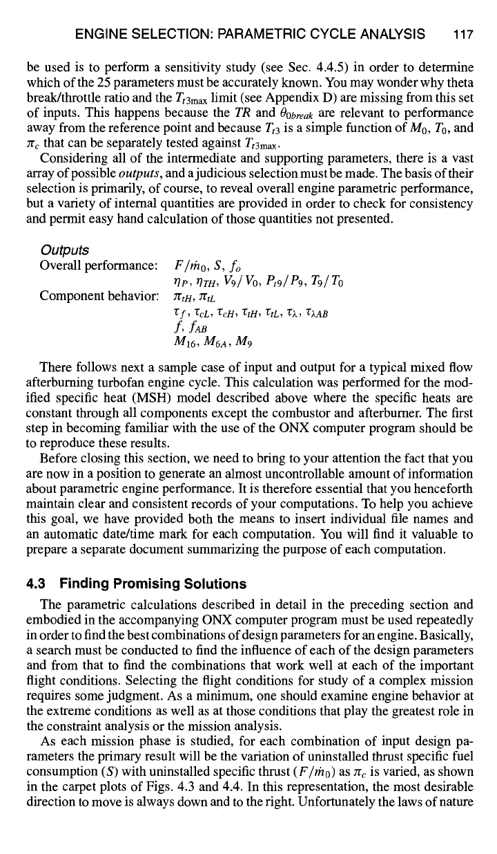
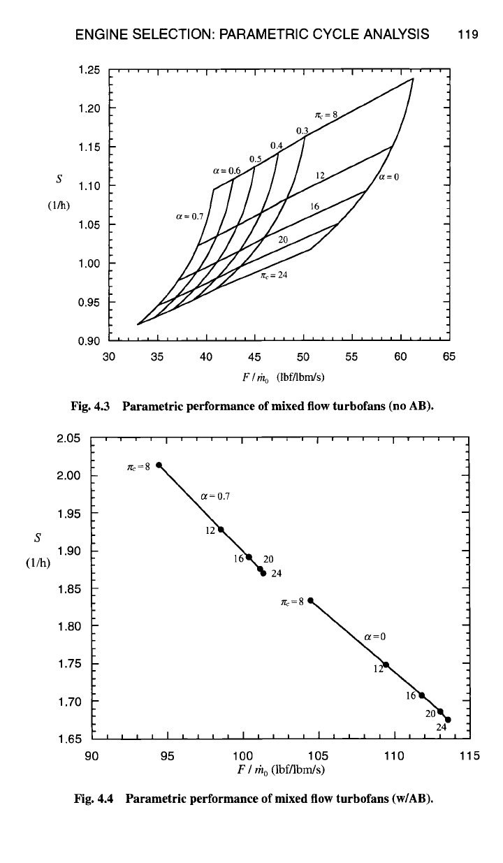
As each mission phase is studied, for each combination of input design pa-
rameters the primary result will be the variation of uninstalled thrust specific fuel
consumption (S) with uninstalled specific thrust (F/rho) as nc is varied, as shown
in the carpet plots of Figs. 4.3 and 4.4. In this representation, the most desirable
direction to move is always down and to the right. Unfortunately the laws of nature

Sample ONX Computer Output
On-Design Calcs (ONX V5.00) Date: X/XX/XX X:XX:XX PM
File: E1ON.onx
Turbofan Engine with Afterburning
using Variable Specific Heat (VSH) Model
******************* Input Data *************************
Mach No = 1.600 Alpha = 0.400
Alt(ft) = 35000 Pif/PicL = 3.800/3.800
TO (R) = 394.10 Pi d (max) = 0.960
P0 (psia) = 3.467 Pi b = 0.950
Density = .0007352 Pin = 0.970
(Slug/fl^3) Efficiency
Burner = 0.999
Mech Hi Pr = 0.995
Mech Lo Pr = 0.995
Fan/LP Comp = 0.890/0.890 (ef/ecL)
Tt4 max = 3200.0 R HP Comp = 0.900 (ecH)
h - fuel = 18400 Btu/lbm HP Turbine = 0.890 (etH)
CTO Low = 0.0000 LP Turbine = 0.900 (etL)
CTO High = 0.0150 Pwr Mech Eft L = 1.000
Cooling Air #1 = 5.000 % Pwr Mech Eft H = 0.990
Cooling Air #2 = 5.000 % Bleed Air = 1,000 %
P0/P9 = 1.0000
** Afterburner **
Tt7 max = 3600.0 R Pi AB = 0.950
Eta A/B = 0.990
*** Mixer *** Pi Mixer max = 0.970
********************** RESULTS *************************
Tau r = 1.510
Pi r = 4,237
Pi d = 0.924
Tt4/T0 = 8.120
PTO Low = 0,00 KW
PTO High = 301.34 KW
Ptl6/P0 = 14.876
Pt6/P0 = 13.792
Pi c = 16,000
Pi f = 3.8000
Tan f = 1.5372
Etaf = 0.8681
Pi cL = 3.800
EtacL = 0.8681
Pi cH = 4.2105
Tau cH = 1.5734
Eta cH = 0.8795
PitH = 0.4693
Tau tH = 0.8457
Eta tH = 0.8980
Pi tL = 0.4939
Tau tL = 0.8504
Without AB
Pt9/P9 = 12.745
f = 0.03127
F/mdot
S
T9/T0
V9/V0
M9/M0
A9/A0
A9/A8
= 62.859 lbf/(lbm/s)
= 1.1386 (lbm/hr)/lbf
= 2.5428
= 2.268
= 1,439
= 1.136
= 2.372
Thrust = 12572 lbf
Thermal Eft = 55.89 %
Propulsive Eft = 61.62 %
a0 (ft/sec) = 974.7
V0 (ft/sec) = 1559.4
Mass Flow = 200.0 lbm/sec
Area Zero = 5.422 sqfi
Area Zero* = 4.336 sqft
Tt16ff0 = 2.3124
Tt6/T0 = 5.7702
Tau ml = 0.9684
Tan m2 = 0.9742
Tan M = 0.8206
Pi M = 0.9771
Tau cL = 1.5372
M6 = 0.4000
M16 = 0.5159
M6A = 0.4331
AI6/A6 = 0.1844
Gamma M = 1.3165
CP M = 0.2849
Eta tL = 0.9070
With AB
Pt9/P9 = 12.418
f = 0.03127
f AB = 0.03222
F/mdot = 110.634 lbf/(lbm/s)
S = 1.6878 (lbmlhr)/lbf
T9/T0 = 5.3364
V9/V0 = 3.142
M9/M0 = 1.416
A9/A0 = 1.775
A9/A8 = 2.489
Thrust = 22127 lbf
Thermal Eff = 47.40 %
Propulsive Eft = 49,01%
118
ENGINE SELECTION: PARAMETRIC CYCLE ANALYSIS 119
S
(l/h)
1.25 .... i .... i .... i .... i .... i .... i ....
1.20 ~'~ -- S~
0.3
1.15 0.4
0.5
s
1.10
O,'h)
1.05 a~
1.00
f~,.=
24
(.=
0.95
0,90 i i t i I i i , , I .... I .... I .... I .... I ....
30 35 40 45 50 55 60 65
F / rh o
(lbf/lbm/s)
Fig. 4.3 Parametric performance of mixed flow turbofans (no AB).
2.05
2.00
1.95
1.90
1.85
1.80
1.75
1.70
1.65
90
''''1''''1 I''''1''''
'2 4
~=0
12
16
24
I I I I I I I I ' I , , i , l J , , , I , , , ,
95 100 105 110
F / th o (lbf/lbm/s)
Fig. 4.4 Parametric performance of mixed flow turbofans (w/AB).
115
120 AIRCRAFT ENGINE DESIGN
do not always fully cooperate, and there is usually a tradeoff between S and
F/rho,
where one can be improved only at the expense of the other. Be prepared for intu-
ition to go wrong at this point because increases in cycle temperatures (e.g., rz) and
component pressure ratios (e.g., zrc) do not always lead to improved performance.
You may find recourse to propulsive, thermal, and overall efficiency and Eq. (4.32)
to be helpful in discovering the root cause of parametric performance trends. This
explains why they are always included in the output quantities. To make use of the
computed results, initial goals must be established for S and
F/rho,
as described
next.
4.3.1 Uninstalled Specific Fuel Consumption (S)
Clear targets can be set for S because of the initial expectations already es-
tablished by mission analysis. The main caution to be raised is that the mission
analysis is based on
installed
specific fuel consumption (TSFC), while the cycle
analysis yields
uninstalled
specific fuel consumption (S). A good rule of thumb
is that installed exceeds uninstalled by 0 to 10%, depending on the situation (see
Chapter 6), or a conservative average value of about 5%. Hence, the most revealing
way to display the parametric analysis results is to plot the target or goal value of
S on the carpet plot of S vs
F/rho.
The totality of results must be used with care. On the one hand, reference point
values of S may be different than the corresponding off-design values that will
be computed later. Also, installation effects will vary with distance from the final
reference point. On the other hand, it is needlessly restrictive to require that the
specific fuel consumption be less than or equal to the target value at
every
flight
condition. It is necessary only that the total fuel consumption, integrated over the
entire mission, meets its goal. Therefore, a higher fuel consumption on one leg may
be traded for a lower fuel consumption on another, provided that the integrated gains
equal or outweigh the losses. A good general rule is to concentrate on reducing S
for those legs using the most fuel (i.e., smallest 17) in the mission analysis.
4.3.2 Uninstalled Specific Thrust (F/mo)
Because the physical size of the engine (i.e., rho design) is not known at this
point, no stated target for
F/rho
exists. Although the size of the engine can always
be increased to provide the needed total thrust, it is always desirable to achieve large
values of
F/rho
in order to decrease the size (as well as the initial and maintenance
cost, volume, and weight) of the engine. Once again, it should be noted that a
constraint analysis is based on
installed
thrust (T), while the cycle analysis yields
uninstalled
thrust (F), with F exceeding T by 0 to 10% depending on the situation
and distance from the final design point.
A good general rule here is to concentrate on increasing
F/rho
for those legs that
formed the boundary of the solution space in the constraint analysis. The lower
thrust required for flight conditions away from that boundary will be attained by
reducing Tt7 and/or Tt4. In fact, for flight conditions that require considerably less
than the available thrust, it is more realistic to run these parametric computations
at less than the maximum values of Tt7 and/or Tt4.
Even though no precise goal for
F/rho
is available, ballpark figures can be easily
generated using ONX, a representative sample of which is given in Table 4.1.