Mattingly J.D., Heiser W.H., Pratt D.T. Aircraft Engine Design
Подождите немного. Документ загружается.

80 AIRCRAFT ENGINE DESIGN
The conclusion, then, is that the AAF can have a practical (and affordable) size,
but only if reliable nonmetallics having competitive strength, durability, and repara-
bility become available according to schedule. Because the choices of
TsL/Wro =
1.25 and
Wro/S
= 64.0 lbf/ft a have already been made, the description of the
AAF at this stage of design, in dimensional terms to three significant figures,
using
WF/WTo =
0.2787, is
WTo
= 24,000 lbf
TsL
= 30,000 lbf
S = 375
ft 2
We = 26601bf
WE = 14,650 lbf
Wv = 6,6901bf
This information can be used to generate a number of perspectives on the na-
ture and shape of the corresponding aircraft. For example, because afterbuming
military engines ordinarily have
TsL
in the range of 15,000-35,000 lbf, the deci-
sion may remain open as to whether the AAF is a single- or twin-engine design.
Further, if it is assumed that the wing is a delta planform with an aspect ratio
of 2, the total wing span will be approximately 27 ft. Because the takeoff pay-
load fraction
(Hip~ WTo)
of fighter aircraft is usually in the range of 0.05-0.10,
the AAF value of 0.111 shows that it is quite a workhorse. For further refer-
ence,
We / Wzo
for the largest cargo and transport aircraft is in the range of only
0.15-0.25.
3.4.3 First Reprise
This is the first opportunity to evaluate some of the key assumptions that have
been made along the way. Hopefully, they will be found to be sufficiently accurate
that the present results are acceptable. Otherwise, it may be necessary to reiterate
the process up to this point with new assumptions.
During the calculation of various other boundaries on the constraint diagram,
it was necessary to assume values for the weight fraction (fl). In fact, /3 was
taken to be 1.0 at takeoff, 0.56 at landing, and 0.78 everywhere else (an estimate
of the aircraft maneuver weight). The maneuver weight (50% fuel, 2 AIM-9Ls,
1 ammunition) and its associated fl can be estimated now that the aircraft
and
takeoff weight has been determined. The easiest method is to subtract the weight of
1 ammunition from the takeoff weight
(Wro)
to obtain
_12 fuel, AMRAAMs, and
a maneuver weight of 19,730 lbf or/3 = 0.8221. Because this weight fraction
is greater than the estimated 0.78 used in the constraint analysis of Chapter 2,
the associated constraint lines will require a larger thrust loading for each wing
loading. In addition the results of the mission analysis give a better estimate of
the takeoff and landing weight fractions (see Table 3.E3). The new estimates for
/3 resulting from the mission analysis and the estimate of the maneuver weight
encourage a reconsideration of the legs that bound the solution space of Fig. 2.E3,
as summarized next:
1) Takeoff, Mission Phase 1-2: Because the real/3 must be less than 1.0, the
takeoff constraint boundary is conservative and is less critical than originally es-
timated.
MISSION ANALYSIS 81
2) Combat Acceleration: The maneuver fl value of 0.8221 is greater than the
initial estimate of 0.78, and therefore this constraint requires a larger thrust loading
of 0.969 at a wing loading of 64 lbf/ft 2, more than originally estimated.
3) Supercruise, Mission Phase 6-7 and Maneuver Weight: Here the initial fl
value for mission phase 6-7 of 0.8880 is higher than the initial estimate, and the
required thrust loading increases to 0.934 at a wing loading of 64 lbf/ft 2, much less
than the selected thrust loading of 1.25. The maneuver fl value requires a thrust
loading of 0.930 at a wing loading of 64 lbf/ft 2, less than that of mission phase
6-7.
4) 5g turn at 0.9M/30 kft, Maneuver Weight: Here the maneuver fl value for
turn is higher than the initial estimate, and the required thrust loading increases to
1.261 at a wing loading of 64 lbf/ft 2, slightly more than the selected thrust loading
of 1.25. If the difference were larger, a reconsideration of the thrust loading would
be appropriate, but this small change does not warrant a reselecfion. Chapter 6 will
better define the required thrust loading.
5) 5g turn at 1.6M/30 kft, Maneuver Weight: Here the maneuver fi value for
turn is higher than the initial estimate, and the required thrust loading increases to
0.931 at a wing loading of 64 lbf/ft 2.
6) Landing, Mission Phase 13-14: In the calculation of landing distance using
a drag chute (Sec. 2.4, Mission Phase 13-14), it was assumed that the wing area
(S) was 500 f12, whereas the presently derived value is 375 ft 2. Substituting the
new value would have the effect of increasing the chute drag coefficient to 0.7131.
When combined with the new fl value of 0.6668, the
Wro/S
boundary is moved
to 64 lbfffl 2.
7) 1.8M/40 kft, Maneuver Weight: Here the maneuver fi value for turn is higher
than the initial estimate, and the required thrust loading increases to 0.728 at a
wing loading of 64 lbf/ft 2, much less than the selected thrust loading of 1.25.
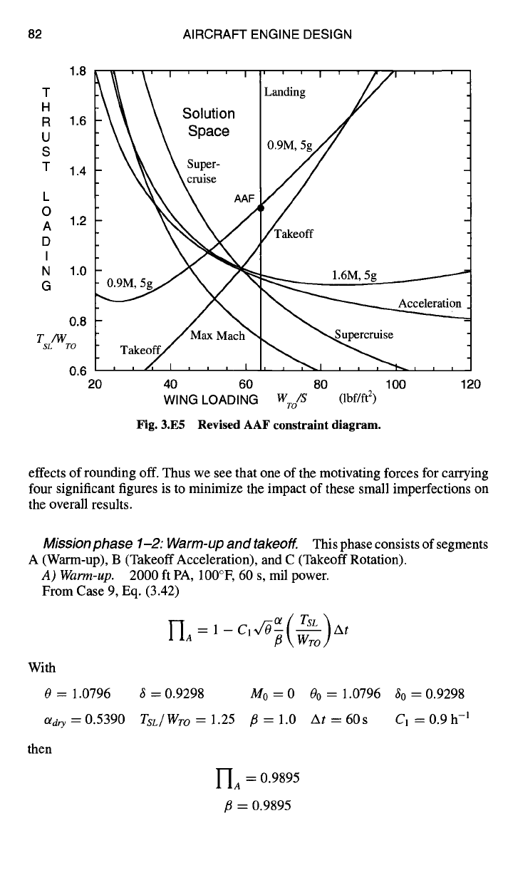
A revised constraint, diagram is given in Fig. 3.E5. Note that the AAF design
point is now on the landing constraint line, slightly below the 0.9M/30 kft 5g turn
line, and above the other constraint lines. Further work in this textbook will focus
on the engine and the design thrust loading
(TsL/Wro)
may change from its current
design value of 1.25. However the wing loading
(WTo/S)
is assumed to remain at
64 lbf/fl 2.
3.4.4 Complete AAF Weight Fraction Computations
The RFP mission of the AAF is flown in this section to find the weight fraction
of each mission segment and phase. These calculations are the source of the data
given in Table 3.E3 and Fig. 3.E3. The same procedure is used in each weight
fraction calculation. First, the applicable weight fraction equation from Sec. 3.2 is
written. Next, data are given to determine the values of all quantities in the order
they appear from right to left in the weight fraction equation. Finally, the weight
fraction and the accumulated fl are calculated. Please note that for all mission legs
we shall use
fli
for
[~avg
and K2 = 0.
Careful note should be taken of the fact that these hand calculations com-
pletely duplicate the AEDsys Mission Analysis computations obtained by using
the AAEAED file. Any minor differences are simply the result of the cumulative
82 AIRCRAFT ENGINE DESIGN
1.8
T
H
R 1.6
U
S
T 1.4
L
O
A 1.2
D
I
N 1.0
G
0.8
T/W
SL TO
0.6
20
~
~I ' ' ' I ' ' ' I ' ' I
Solution
Landing
'/
\
\
\ Supe -
\\\
~ruise AAF
r Takeoff
40 60
WING LOADING
Fig. 3.E5
5g~
ce at
80 100 120
W /S
(lbf/ft 2)
TO
Revised AAF constraint diagram.
effects of rounding off. Thus we see that one of the motivating forces for carrying
four significant figures is to minimize the impact of these small imperfections on
the overall results.
Mission phase 1-2: Warm-up and takeoff.
This phase consists of segments
A (Warm-up), B (Takeoff Acceleration), and C (Takeoff Rotation).
A) Warm-up.
2000 ft PA, 100°E 60 s, mil power.
From Case 9, Eq. (3.42)
With
0 = 1.0796
ad~ = 0.5390
then
UA -~- 1- Cl~/-O~(-~o)mt
3=0.9298
M0=0
00=1.0796 30=0.9298
TsL/Wro=l.25
fl=l.0 At=60s Cl=0.9h -a
1--IA "~" 0.9895
fl = 0.9895
MISSION ANALYSIS 83
B) Takeoff acceleration.
2000 ft PA, 100°F,
kro
= 1.2,/Zro = 0.05,
CDR =
0.07,
C L
max =
2.0,
Macce I
= 0.1,
max power.
From Case 4, Eqs. (3.21) and (3.22)
1-I" = exp [ -(C' + C2M)~/-O \ ~- u,l ~ [
With
Vro
evaluated from Eq. (2.21), the takeoff estimate of~ro from Chapter 2,
Sec. 2.4.3, and a evaluated at
Maccel,
and with
/~ = 0.9895 a = ll60ft/s /Zro = 0.05
Wro/S
= 641bf/ft 2
CLmax =
2.0
kro
= 1.2
Mro
= 0.1819 0 = 1.0796 6 = 0.9298
0o = 1.0818 60 = 0.9363
Otwet
= 0.9006
TsL/Wro
= 1.25 u = 0.2725
C1 + C2M
= 1.627h -1
then
C) Takeoff rotation.
From Case 10, Eq. (3.44)
I-Ic = 1--(C1
"}-C2M)~IIo~-~(~o)tR
With
tR
=3S
6 = 0.9298
TSL/Wro
= 1.25
then
I
-I8 = 0.9958
/~ = 0.9853
Mro/2000
ft PA, 100°F,
tR
= 3 s, max power.
/3 = 0.9853 0 = 1.0796
6o = 0.9515
Olwe t
= 0.9003
I
-Ic = 0.9984
The weight fraction for mission phases 1-2 is the product of the weight fractions
for segments A, B, and C.
I"I : I-IA FIB I"Ic :
0.9837
12
/3 = 0.9837
Macce I = O. 1
Vro
= 211.1 ft/s
q = 45.601bf/ft 2
~ro = 0.3612
Mro
= 0.1819
00 = 1.0867
C1 --k C2M =
1.649 h -1
84 AIRCRAFT ENGINE DESIGN
Mission phase 2-3: Accelerate and climb.
This phase consists of segments
D (Horizontal Acceleration) and E (Climb and Acceleration).
D) Horizontal acceleration. Mro -+ Mct/2000
ft PA, 100°E mil power.
For this Mach number change of 0.1819 to 0.70, a single interval calculation will
suffice. The Climb/Acceleration Weight Fraction Calculation Method of Sec. 3.4.1
is used with properties evaluated at the middle state point (M = 0.4410, 2000
ft PA, 100°F) and fl = fli.
With
(a/astd)i
= 1.039
V/ = 211.1 ft/s
(a/a~td)f
= 1.039
Vf
= 812.0ft/s
A(vZ/2go)
= 9555 ft
Ah = 0.0ft
AZ e ~---
9555 ft
/3 = 0.9837
Wro/S
= 64 lbf/ft 2
8 = 0.9298
M = 0.4410
CL = 0.2351
Ka =0.18, K2=0.0
CDo = 0.014
CD = 0.02395
CD/CL
= 0.1019
0 = 1.0796
0o = 1.1215
8o = 1.0627
Otd~y = 0.5264
Tsz/Wro
= 1.25
u = 0.1524
TAs/W
= ll,270ft
(a/astd)
= 1.039
V = 511.5 ft/s
At = 32.97 s
As = 2.775 n miles
C1/M
+ C2 = 2.340 h -1
then
H
e = 0.9935
fl = 0.9773
Note that
Aso
= 2.775 n miles and AtD = 32.97 S.
E) Climbandacceleration. McL/2OOOftPA,
100°F--+
BCM/BCA, milpower.
The weight fraction of this mission segment is calculated along the minimum
time-to-climb path depicted in Fig. 3.E2. In our illustrative example of Sec. 3.4.1,
we found the weight fraction of this segment, using a single gross interval, to
be 0.9812. Here we shall use the three successive integration intervals given in
Table 3.E4 for our calculations, applying Eq. (3.20) to each. We use/3 =/3i and
the values of the state properties (or, 0,
Co/CL,
and V) at the mid state point of each
interval to obtain an appropriate average value of the required properties. The fli of
each succeeding interval is obtained by multiplying the fli of the preceding interval
by I-I. By comparing the final result with that of Sec. 3.4.1, we can determine
whether it is necessary for sufficient accuracy to break the climb/acceleration
calculations into still smaller intervals.
Following this approach, the Climb/Acceleration Weight Fraction Calculation
Method of Sec. 3.4.1 was used to obtain the results given in Table 3.E5.
HE = Ha Hb Hc = 0.9806
MISSION ANALYSIS 85
Table 3.E4 Segment F,---schedule and intervals
Integration interval
Climb schedule (state points)
Altitude, fl
Mach number a b c
2,000 (100 °F) 0.70
9,000 0.775
16,000 0.85
23,000 0.875
30,000 0.90
36,000 0.90
42,000 0.90
Initial
Mid
Final
Initial
Mid
Final
Initial
Mid
Final
This result differs insignificantly from the earlier result of the single gross in-
terval calculations for the illustrative example in Sec. 3.4.1. The amount of fuel
consumed for this phase has changed by only 3%. We should therefore not con-
sider breaking this phase into even finer intervals. Summarizing, then, we have the
following results for Mission Phase 2-3:
As23 =
Asp + Ase
= 23.04 n miles
At23 =
Ato
+ AtE = 2.906 min.
H = HD HE = 0.9742
23
fi = 0.9584
Mission phase 3-4: Subsonic cruise climb. BCM/BCA,
As23 -}- As34 =
150 n miles, mil power.
This is a type B (Ps = 0, T = D + R) mission leg for which full thrust is not
usually applied. Even so, we shall use a conservative full thrust value of
TSFC
from Sec. 3.4.1 for all type B legs in these calculations.
From Case 7, Eq. (3.29), with
COR = K2 = 0
{ ~ (C1-'[- C2McRIT)AS34 I
]7.. = exp
MCRIT as----~d I
34
Table 3.E5 Segment E----climb/acceleration results
Ah,
AV2/2gc,
AZe,
TAs/W,
At,
As, C]/M +
C2,
Interval ft ft ft
CD/C L lg
ft min n miles h-
1 I-I
a 14,000 2210 16,210 0.1601 0.1962 20,170 0.4915 4.067 1.462 0.9927
b 14,000 2.254 14,000 0.1384 0.2696 19,170 0.6913 6.119 1.329 0.9937
c 12,000 -662.4 11,340 0.1111 0.3755 18,150 1.1728 10.086 1.3 0.9941
40,000 1550 41,550 57,490 2.356 20.27
86
with
then
AIRCRAFT ENGINE DESIGN
As34 = 127.0n miles K1 = 0.18
Coo
= 0.016
Mcmr
= 0.9
C1 -+- C2McRIT
---- 1.1700 h -1
I
-I= 0.9736
34
fl = 0.9331
Note should be taken of the fact that fuel consumption could be further reduced
for this phase by capitalizing on the range factor as described in Sec. 3.2.7, Case 7.
Consequently, the preceding result may regarded as conservative.
with
then
Mission phase 4-5: Descend. BCM/BCA --~ MCAp/30
kfc
-I = 1.0
45
fl = 0.9331
Mission phase 5-6: Combat air patrol.
30 kft, 20 min., mil power.
From Case 8, Eq. (3.40), with
CoR = K2 = 0
I-'I = exp{-(C1
+ C2McAP)W/O~At}
56
At = 1200s 0 = 0.7941 8 = 0.2976
K1 = 0.18
Coo
= 0.014 C~ = 0.2789
MCA P =
0.6970
C1 + C2M
= 1.1091h -1
--I= 0.9675
56
/~ = 0.9027
At the end of combat air patrol
MCA P =
0.6856 from Case 8, Eq. (3.38).
Note should be taken of the fact that fuel consumption could be further reduced
for this phase by capitalizing on the endurance factor as described in Sec. 3.2.8,
Case 8. Consequently, the preceding result may regarded as conservative.
Mission phase 6-7: Supersonic penetration.
This phase consists of seg-
ments F (Horizontal Acceleration) and G (Supersonic Penetration).

MISSION ANALYSIS
Table 3.E6 Segment F--horizontal acceleration
87
AZe, TAs/W, At, As, CI/M + C2,
Interval
Mi Mf Mavg
ft
Co/CL u
ft min n miles h -I
a 0.6856 0.95 0.8178 6,652 0.1085 0.1697 8,011 0.2567 2.062 2.227 0.9956
b 0.95 1.23 1.0900 9,389 0.2537 0.2907 13,240 0.2332 2.496 1.738 0.9943
c 1.23 1.5 1.3650 11,340 0.4192 0.3552 17,590 0.1828 2.452 1.442 0.9937
-- E 27,380 -- 38,840 -- 0.6727 7.010 -- --
F) Horizontal acceleration. MCAP
--+
1.5M/30 kft, max power.
This acceleration calculation is divided into the three intervals shown in
Table 3.E6. The initial, final, and average Mach number of each interval and h =
30,000 ft are used in the Climb/Acceleration Weight Fraction Calculation Method
of Sec. 3.4.1. The calculated results are given in Table 3.E6.
Then
I-IF = I--Ia Ub Uc =
0.9837
/3 = 0.8880
It is interesting to note from Table 3.E6 that the total mission weight specific
work is 38,840 ft with 70.49% used to increase the mechanical kinetic energy
of the airplane. The remaining 29.51% is dissipated into nonmechanical energy
of the airplane/atmosphere system. A single gross interval calculation for this
segment gives higher values of total time and total ground distance by 1.16% and
4.22%, respectively, and lower values of weight fraction and specific thrust work
by 0.024% and 0.33%, respectively. Also note that Ass = 7.01 n miles.
G) Supersonic penetration.
1.5M/30 kft, AsF + Asc =100 n miles, no after-
burning.
From Case 5, Eq. (3.23), with
CoR = 0
with
then
Asa = 92.99 n miles
CL = 0.05731
CD
= 0.02889
C1/M
-t-
C2 :
0.9 h -1
K1 : 0.27
CD/CL
: 0.5040
-Ic = 0.9382
Segments F and G together yield
U = U F 1--IG =
0.9231
67
/3 = 0.8331
6 = 0.2976
Coo
= 0.028
88 AIRCRAFT ENGINE DESIGN
Mission phase 7-8: Combat.
This phase consists of segments H (Fire
AMRAAMs), I (Combat Turn 1), J (Combat Turn 2), K (Horizontal Accelera-
tion), and L (Fire A1M-9Ls and ½ ammo).
H) Fire AMRAAMs.
652 lbf.
From Eq. (3.47), and since fl
Wro
= W7 here,
t ~ WTO -- WpE1 WpE1
- 1 - --
Wro ~ Wro
with
then
WpE 1 =
652 lbf
= 0.8331
Wro
= 24,0001bf
fl WTO -- WpE1
--
0.9674 and fl = 0.8060
Wro
I) Combat turn
1. 1.6M/30 kft, one 360 deg 5g sustained turn, with after-
burning.
From Case 6, Eq. (3.25), with
CDR = 0
nfD
I-II=exp{_(CI+C2M)~/-~(___~_L ) 2zrNV ]
g0 /
with
0 = 0.7941
[ 0.7821 wet }
ot = 0.4444 dry
K1 = 0.290
nCo/CL
Co/CL
= 0.1883
Olreq
= ~~ - 0.6070
CI + C2M
= 1.693 h -1 linearly interpolated
then
3 = 0.2976
I
CI + CzM =
1.380
Coo
= 0.028
0o = 1.201
CL = 0.2286
Co = 0.04305
%AB
= 48.15
V = 1592ft/s
--II = 0.9753
J) Combat turn 2.
burning.
From Case 6, Eq. (3.25), with
Cog = 0
1--i:=exp{_(Cl+C2M)v/-~(n~_~D L / go n2~/~--I
3o = 1.265
fl = 0.7860
0.9M/30 kft, two 360 deg 5g sustained tums, with after-
MISSION ANALYSIS
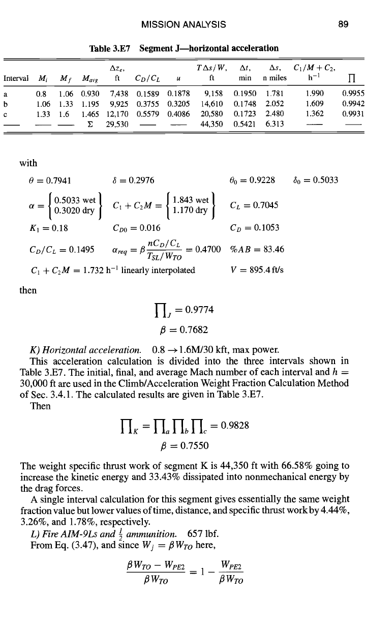
Table 3.E7 Segment J--horizontal acceleration
89
Aze, TAs/W, At,
As,
C1/M + C2,
Interval
Mi Mf Mavg ft CD/CL
u ft min n miles h-I ]7
a 0.8 1.06 0.930 7,438 0.1589 0.1878 9,158 0.1950 1.781 1.990 0.9955
b 1.06 1.33 1.195 9,925 0.3755 0.3205 14,610 0.1748 2.052 1.609 0.9942
c 1.33 1.6 1.465 12,170 0.5579 0.4086 20,580 0.1723 2.480 1.362 0.9931
E 29,530 44,350 0.5421 6.313
with
0 = 0.7941 3 = 0.2976 00 = 0.9228
{ 0"5033 wet/dry _ { 1.843 wet }dry
ot = 0.3020 | CI +C2M = 1.170 Cc = 0.7045
K1 = 0.18 Coo = 0.016 Co = 0.1053
nCD/CL
Co/ CL = 0.1495 Otreq = P ~---"-/'~U-~,, -- 0.4700 %AB = 83.46
ISL/ vvTO
C1 + C2M = 1.732 h -l linearly interpolated V = 895.4 ft/s
then
-'L = 0.9774
30 = 0.5033
fl = 0.7682
0.8 --+ 1.6M/30 kft, max power.
K) Horizontal acceleration.
This acceleration calculation is divided into the three intervals shown in
Table 3.E7. The initial, final, and average Mach number of each interval and h =
30,000 ft are used in the Climb/Acceleration Weight Fraction Calculation Method
of Sec. 3.4.1. The calculated results are given in Table 3.E7.
Then
VIK = rio I-Ib I-If =
0.9828
fl = 0.7550
The weight specific thrust work of segment K is 44,350 ft with 66.58% going to
increase the kinetic energy and 33.43% dissipated into nonmechanical energy by
the drag forces.
A single interval calculation for this segment gives essentially the same weight
fraction value but lower values of time, distance, and specific thrust work by 4.44%,
3.26%, and 1.78%, respectively.
L) Fire AIM-9Ls and ~ ammunition. 657 lbf.
From Eq. (3.47), and since Wj = fl Wro here,
fl Wro - Wpz2 Wpe2
3 Wro 3 Wro