Mattingly J.D., Heiser W.H., Pratt D.T. Aircraft Engine Design
Подождите немного. Документ загружается.

ENGINE SELECTION: PARAMETRIC CYCLE ANALYSIS 131
S
(l/h)
2.00
1.95
1.90
1.85
1.80
1.75
1.70
1.65
1.60
~=5
a=
0.4
c¢=0
15
Target or Goal
25~m _m
95 100 105 110 115 120
F / rh 0 (lbfflbrrds)
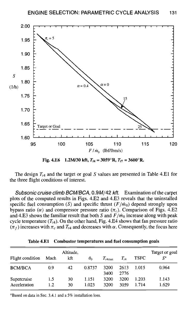
Fig. 4.E6 1.2M/30 kft, Tt4
--
3059°R, Tt7 = 3600°R.
The design Tt4 and the target or goal S values are presented in Table 4.El for
the three flight conditions of interest.
Subsonic cruise climb BCM/BCA,
0.9M/42 kft.
Examination of the carpet
plots of the computed results in Figs. 4.E2 and 4.E3 reveals that the uninstalled
specific fuel consumption (S) and specific thrust
(F/rho)
depend strongly upon
bypass ratio (or) and compressor pressure ratio (Trc). Comparison of Figs. 4.E2
and 4.E3 shows the familiar result that both S and
F/rho
increase along with peak
cycle temperature (Tt4). On the other hand, Fig. 4.E4 shows that fan pressure ratio
(:rf) increases with Jrc and
Tt4
and decreases with ~. Consequently, the focus here
Table 4.El Combustor temperatures and fuel consumption goals
Altitude, Target or goal
Flight condition Mach kft 0o
Tt4ma x Tt4
TSFC S a
BCM/BCA 0.9 42 0.8737 3200 2613 1.015 0.964
3400 2776
Supercruise 1.5 30 1.151 3200 3200 1.203 1.143
Acceleration 1.2 30 1.023 3200 3059 1.714 1.629
aBased on data in Sec. 3.4.1 and a 5% installation loss.
132 AIRCRAFT ENGINE DESIGN
will be upon the selection of useful ranges of t~ and Zrc, and consideration of
Tt'f
and Tt4 will be delayed pending later results.
Increasing ot alone causes both
F/rho
and S to decrease, in accordance with
normal expectations for subsonic turbofan engines, as the available exhaust kinetic
energy is spread over more incoming air. Because the slope of the line of constant
Zrc shows that
F/rho
is decreasing percentage-wise roughly twice as fast as S, it
does not seem advisable to choose an ot greater than 0.5. Conversely, because S
meets the target or goal for moderate to high pressure ratios, no a less than 0.3
should be considered. Thus, the best ~ for this flight condition is probably in the
range of 0.3-0.5.
Increasing Zrc alone produces a more complex behavior of
F/rho
and S because a
maximum of
F/rho
occurs while S continuously decreases. This behavior is typical
of turbine engines, as demonstrated in Refs. 1 and 2. The maximum value of
F/rho
is due to the simple fact that increasing values of Jrc (and thus
Tt3)
eventually limit
the amount of fuel than can be added before the allowable
Tt4
is reached. One should
logically select values of Zrc that are located below the knee of the curve, but not
so far below that
F/rho
is falling rapidly for slight reductions in S. Moreover, no
Zrc should be chosen that exceeds reasonable expectations, with that value today
being in the range of 35-40. Computations reveal, however, that Zrc cannot reach
that limit at high Mach flight conditions before
Tt3
exceed s current capabilities
(Zt3max >
1700°R). Taken together, these reasons indicate that Zrc should be held
in the range of 20-30 for this flight condition.
Supersonic penetration and escape dash,
1.5M/30 kft. Very similar re-
marks to those just stated, both qualitative and quantitative, can be made about the
influence of zrc, zrf, a, and
Tt4 on
S and
F/rho
at this flight condition. The main
differences, as illustrated by the carpet plot of Fig. 4.E5, are that
F/rho
decreases
more rapidly with zrc as well as less rapidly with a in the critical area below the
knee and that there is no sign of choking of the core flow at the highest allowable
values of zr¢. Taking these factors into account, including the special need for high
thrust at this flight condition, the useful ranges of parameters are 15 < Zrc < 25
and 0.3 < a < 0.4.
Supersonic acceleration,
1.2M/30 kft. The carpet plot of the computed
results in Fig. 4.E6 reveal that both S can be reduced and
F/mo
increased by
increasing 7r¢ and reducing ~. Again, changing either Tt4 or Tt7 would have the
usual effect of increasing both S and
F/rno.
By this time it has become clear that the desired fuel consumption goals can
be achieved at some flight conditions, but not all. Consequently, the focus of our
search must continue to be on reduced fuel consumption over the entire mission.
Otherwise, the takeoff weight
(WTo)
of the AAF will certainly grow beyond the
initial estimate of Chapter 3 and, because Eq. (3.49), which determines
Wro,
is extremely nonlinear,
Wro
could become unacceptably large. While it is still
possible that S will be reduced when the engine is throttled back to the required
thrust, or the installation penalties will be less than estimated, or the TSFC models
of Table 4.El are conservative, nothing may yet be taken for granted.
Consequently, the engine performance information generated at this flight condi-
tion shows that 20 < zr¢ < 30 and 0 < ~ < 0.4. The results obtained so far suggest
ENGINE SELECTION: PARAMETRIC CYCLE ANALYSIS 133
that Tt4 and
Tt7
must be limited in order to achieve acceptable fuel consumption,
even though increasing them will increase specific thrust and thereby reduce the
size of the required engine. Their limits will be arbitrarily selected
as
Zt4
~--
3200°R
and T,7 = 3600°R because even these values will push the material and cooling ca-
pabilities expected to be available for the AAF (see Table 4.4). These assumptions,
as well as any others, can be changed if later calculations indicate a positive benefit.
4.4.4 Integrated Results: Range of Design Choices
Before the final ranges of interest for key engine reference point parameters are
selected, two facts must be recognized. First, it makes sense to state them only in
conjunction with a specific flight condition (i.e., P0, To, and M0), preferably one
that will be near the final reference point. Because the AAF must operate well
over the 0.9 < M0 < 1.8/30-45 kft range, it is reasonable to conclude that the
reference point will be in the vicinity of 1.5M/35 kft. Second, any selection must
take into account the normal behavior of parameters when the engine is operating
off-design. A sensible goal is for the key engine parameters to be in their best
ranges at all critical operating points. Thus, the engine will appear to be properly
designed for each.
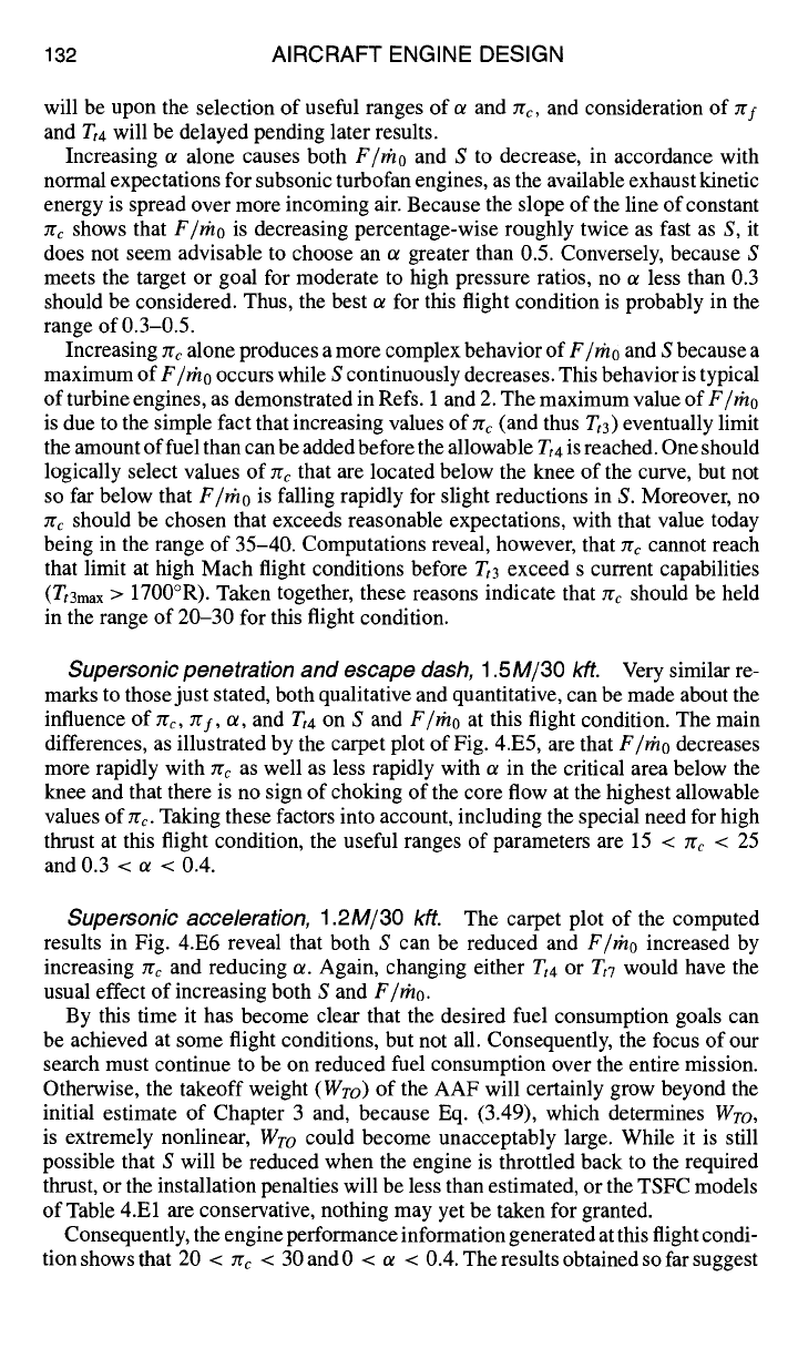
The three critical operating points were therefore added to scaled Figs. 4.6
and 4.8, which are representative of the type of engine emerging for the AAF
application, and the results reproduced here as Figs. 4.E7 and 4.E8.
30
25
Ec
20
15
10
5
0.0
I'''~1 'I'' I
I I , , I , J , ,
I
, , , ,
0.5 1.0 1.5 2.0 2.5
Mo
Alt (kft)
40
30
20
10
SL
Fig. 4.E7 Compressor integrated results.
134 AIRCRAFT ENGINE DESIGN
a
0.6
0.5
0.4
0.3
I ' ' ' ' I ' ' ' ' I ' ' ' '
0.2 .... I .... I ,
~ , t , ~ , ~ I , ~ t
0.0 0.5 1.0 1.5 2.0 2.5
MO
Alt (kft)
SL
10
2O
3O
4O
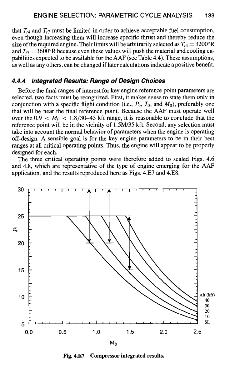
Fig. 4.E8 Bypass ratio integrated results.
Referring to Fig. 4.E7, it can be seen that both the desired and available 7rc
decrease with M0, so that selecting the range 15 < :re < 25 at 1.5M/35 kft will
provide the desired zrc at other flight conditions. In other words, using the trends
of Fig. 4.E7 and imagining that the reference point is moved through the range
15 < Zrc < 25 at 1.5M/35 lift, one sees that the desirable 7rc at other flight conditions
will be included.
Referring to Fig. 4.E8, it can be seen that the situation is different, and that only
the relatively small range of 0.3 < ot < 0.4 at the reference point of 1.5M/35 kft
will provide desirable ot at the other critical flight conditions.
The foregoing reasoning leads to the final choices for the most promising ranges
of key engine design parameters:
1.2_<Mo_< 1.6
30<h <45kft
15 < zr~ _< 25
0.3 <¢z <0.4
3_<7r/ ~5
Tt4 < 3200°R
Tt7 <
3600°R
0.35 < M6 < 0.45
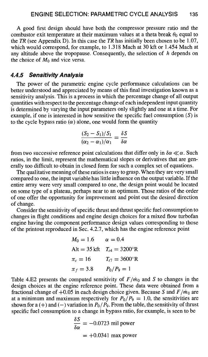
ENGINE SELECTION: PARAMETRIC CYCLE ANALYSIS 135
A good first design should have both the compressor pressure ratio and the
combustor exit temperature at their maximum values at a theta break 00 equal to
the TR (see Appendix D). In this case the TR has initially been chosen to be 1.07,
which would correspond, for example, to 1.318 Mach at 30 kft or 1.454 Mach at
any altitude above the tropopause. Consequently, the selection of h depends on
the choice of M0 and vice versa.
4.4.5 Sensitivity Analysis
The power of the parametric engine cycle performance calculations can be
better understood and appreciated by means of this final investigation known as a
sensitivity analysis. This is a process in which the percentage change of all output
quantities with respect to the percentage change of each independent input quantity
is determined by varying the input parameters only slightly and one at a time. For
example, if one is interested in how sensitive the specific fuel consumption (S) is
to the cycle bypass ratio (~) alone, one would form the quantity
($2 - $1)/$1 ~S
(ot2 - o~1)/Oll got
from two successive reference point calculations that differ only in 6or << or. Such
ratios, in the limit, represent the mathematical slopes or derivatives that are gen-
erally too difficult to obtain in closed form for such a complex set of equations.
The qualitative meaning of these ratios is easy to grasp. When they are very small
compared to one, the input variable has little influence on the output variable. If the
entire array were very small compared to one, the design point would be located
on some type of a plateau, perhaps near to an optimum. Those ratios of the order
of one offer the opportunity for improvement and point out the desired direction
of change.
Consider the sensitivity of specific thrust and thrust specific fuel consumption to
changes in flight conditions and engine design choices for a mixed flow turbofan
engine having the component performance design values corresponding to those
of the printout reproduced in Sec. 4.2.7, which has the engine reference point
M0= 1.6 ~ = 0.4
Alt = 35k~
~4 =
3200 °R
~c = 16 ~7 = 3600 °R
~f = 3.8 Po/P9 = 1
Table 4.E2 presents the computed sensitivity of F/rho and S to changes in the
design choices at the engine reference point. These data were obtained from a
fractional change of +0.05 in each design choice given. Because S and F/rho are
at a minimum and maximum respectively for Po/P9 = 1.0, the sensitivities are
shown for a (+) and (-) variation in P0/P9. From the table, the sensitivity of thrust
specific fuel consumption to a change in bypass ratio, for example, is seen to be
3S
- 0.0723 mil power
got
= +0.0341 max power
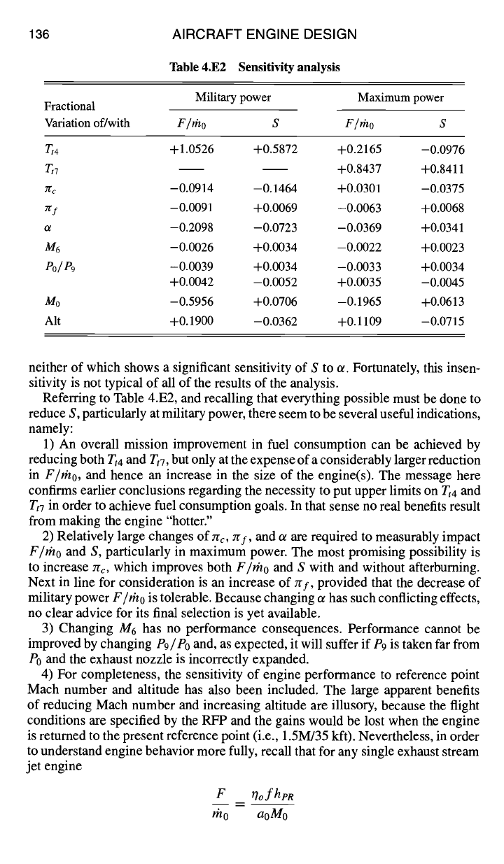
136
AIRCRAFT ENGINE DESIGN
Table 4.E2 Sensitivity analysis
Military power Maximum power
Fractional
Variation of/with F /rho S F /rho S
Tt 4
+1.0526 +0.5872 +0.2165 -0.0976
Tt7 +0.8437 +0.8411
rrc -0.0914 -0.1464 +0.0301 -0.0375
7/'f -0.0091 +0.0069 -0.0063 +0.0068
ot -0.2098 -0.0723 -0.0369 +0.0341
M6 -0.0026 +0.0034 -0.0022 +0.0023
Po/P9 -0.0039 +0.0034 -0.0033 +0.0034
+0.0042 -0.0052 +0.0035 -0.0045
Mo -0.5956 +0.0706 -0.1965 +0.0613
Alt +0.1900 -0.0362 +0.1109 -0.0715
neither of which shows a significant sensitivity of S to or. Fortunately, this insen-
sitivity is not typical of all of the results of the analysis.
Referring to Table 4.E2, and recalling that everything possible must be done to
reduce S, particularly at military power, there seem to be several useful indications,
namely:
1) An overall mission improvement in fuel consumption can be achieved by
reducing both
Tt4
and TtT, but only at the expense of a considerably larger reduction
in F/rho, and hence an increase in the size of the engine(s). The message here
confirms earlier conclusions regarding the necessity to put upper limits
on
Tt4
and
Tt7
in order to achieve fuel consumption goals. In that sense no real benefits result
from making the engine "hotter."
2) Relatively large changes of zr¢, zrf, and ot are required to measurably impact
F/rho and S, particularly in maximum power. The most promising possibility is
to increase Zrc, which improves both F/rho and S with and without afterburning.
Next in line for consideration is an increase of zrf, provided that the decrease of
military power F/rho is tolerable. Because changing ot has such conflicting effects,
no clear advice for its final selection is yet available.
3) Changing M6 has no performance consequences. Performance cannot be
improved by changing P9/Po and, as expected, it will suffer if P9 is taken far from
P0 and the exhaust nozzle is incorrectly expanded.
4) For completeness, the sensitivity of engine performance to reference point
Mach number and altitude has also been included. The large apparent benefits
of reducing Mach number and increasing altitude are illusory, because the flight
conditions are specified by the RFP and the gains would be lost when the engine
is returned to the present reference point (i.e., 1.5M/35 kft). Nevertheless, in order
to understand engine behavior more fully, recall that for any single exhaust stream
jet engine
F ~7ofh?R
mo aoMo

ENGINE SELECTION: PARAMETRIC CYCLE ANALYSIS 137
and
S- l'h f __
aoMo
F 7ohl, R
where 770 is the overall cycle energy conversion efficiency from fuel energy to thrust
work (see Appendix E). Because 7o varies relatively slowly with flight conditions,
the overwhelming effect of decreasing M0 or decreasing a0 (i.e., increasing alti-
tude) is to improve both F/mo and S. Thus, the ranges of M0 and h are retained
in the parameters only to allow the effects of different mission balance points to
be examined.
These sensitivity analysis results lead to the conclusions that 7gf and 7rc should
be selected from the high ends of their respective ranges, while
Tt4
and/or Tt7
should be allowed to drift down from their limiting values. Meanwhile, changes of
o~ and M16 will not have a significant impact on the leading propulsion performance
parameters.
References
IOates, G. C., The Aerothermodynamics of Gas Turbine and Rocket Propulsion, 3rd ed.,
AIAA Education Series, AIAA, Reston, VA, 1997.
2Mattingly, J. D., Elements of Gas Turbine Propulsion, McGraw-Hill, New York, 1996.
3"Gas Turbine Engine Performance Station Identification and Nomenclature." Society of
Automotive Engineers, Aerospace Recommended Practice (ARP) 755A, Warrendale, PA,
1974.
4Reynolds, W. C., and Perkins, H. C., Engineering thermodynamics, 2nd ed., McGraw-
Hill, New York, 1977.
5U.S. Dept. of Defense, "Model Specification for Engines, Aircraft, Turbojet," Military
Specification MIL-E-5008B, Washington, DC, Jan. 1959.
6Oates, G. C., "Performance Estimation for Turbofans with and Without Mixers," Journal
of Propulsion and Power, Vol. 1, No. 3, 1985, pp. 252-256.
7 Gordon, S., and McBride, B., "Computer Program for Calculation of Complex Chemical
Equilibrium Compositions," NASA SP-273, 1971.
5
Engine Selection: Performance Cycle Analysis
5.1 Concept
The parametric cycle analysis of Chapter 4 showed how reference point (design
point or on-design) engine performance was determined by design choices. This
made it possible to examine trends in engine specific performance (specific thrust
and thrust specific fuel consumption) with changes in design variables and to begin
to narrow the desirable range for each design parameter. Now that the first steps
have been taken toward finding an optimum engine for a particular application, it
is time to determine an engine's steady state operating performance.
The object of performance cycle analysis is to determine the engine's perfor-
mance over its operating envelope. The performance of several different engines
can then be compared to reveal trends in engine performance with design choices.
Thus, it is possible to focus in on the most promising designs and to ultimately
find the engine reference point that has the best balanced performance over the
whole mission spectrum. Once an engine cycle and its design choices are made,
the results of the performance cycle analysis are used to size the engine by the
methods presented in Chapter 6. The performance of a selected engine can also
serve to determine how well the thrust lapse model and the fuel consumption es-
timates, used in the constraint and mission analyses of Chapters 2 and 3, are met
by the engine.
Performance analysis differs significantly from parametric analysis. In paramet-
ric (reference or design point) cycle analysis all of the design choices (including the
flight conditions) are free to be selected by the designer, and the engine performance
characteristics per unit mass flow are determined for each selected set of choices.
In contrast, in performance cycle analysis the design choices have been made, and
the performance of this specific reference point engine is needed at all possible
operating conditions. The independent variables in performance analysis are flight
conditions, throttle settings, and nozzle settings. Once the engine is sized and the
mass flow rate specified, performance analysis is employed to determine how a
selected engine performs at all operating conditions within its flight envelope.
The mental image usually attached to this stage of development is that of an
engine of fixed configuration that we have manufactured for testing in a facility
that can simulate the desired flight conditions (see Appendix E). Although the
absolute size of the engine may be arbitrary during performance analysis, and we
may lack most of the details of the geometry of the individual components, it is
still best to think of it as a piece of hardware that we have built in order to explore
the behavior of this reference point engine.
For performance analysis, individual component performance can be modeled
as a function of operating conditions or actual component characteristics can
be obtained from component hardware performance data. These two approaches
139
140
A~
AIRCRAFT ENGINE DESIGN
bleed air
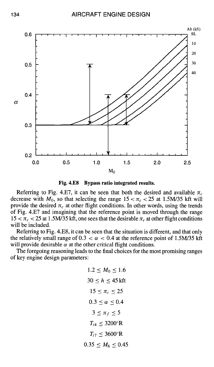
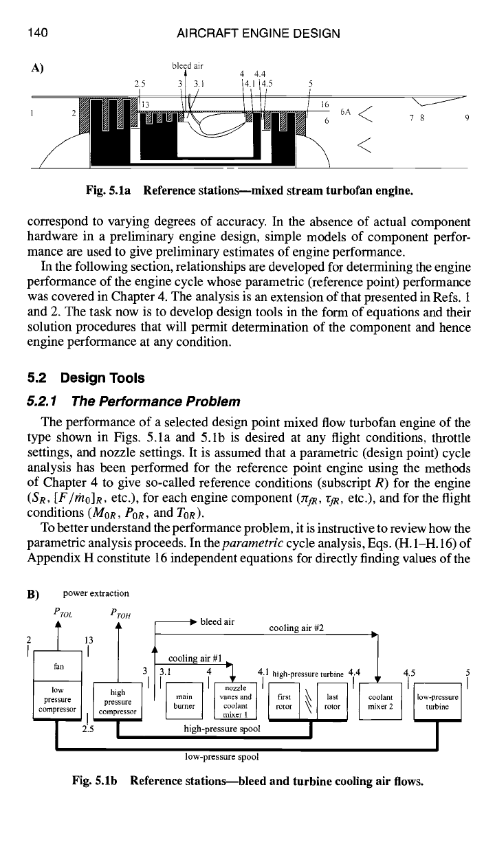
Fig. 5.1a Reference stations---mixed stream turbofan engine.
correspond to varying degrees of accuracy. In the absence of actual component
hardware in a preliminary engine design, simple models of component perfor-
mance are used to give preliminary estimates of engine performance.
In the following section, relationships are developed for determining the engine
performance of the engine cycle whose parametric (reference point) performance
was covered in Chapter 4. The analysis is an extension of that presented in Refs. 1
and 2. The task now is to develop design tools in the form of equations and their
solution procedures that will permit determination of the component and hence
engine performance at any condition.
5.2 Design Tools
5.2.1
The Performance Problem
The performance of a selected design point mixed flow turbofan engine of the
type shown in Figs. 5.1a and 5.1b is desired at any flight conditions, throttle
settings, and nozzle settings. It is assumed that a parametric (design point) cycle
analysis has been performed for the reference point engine using the methods
of Chapter 4 to give so-called reference conditions (subscript R) for the engine
(SR, [F/FnO]R, etc.), for each engine component (TrfR, r/R, etc.), and for the flight
conditions (MoR, POR, and TOR).
To better understand the performance problem, it is instructive to review how the
parametric analysis proceeds. In the parametric cycle analysis, Eqs. (H. 1-H. 16) of
Appendix H constitute 16 independent equations for directly finding values of the
B)
power extraction
PTOL PFOH
2
r
I~ bleed air
13
ire t
i corn
2.5
I cooling air #2 I~
cooling air #1
3.1 4 ~.L 4. l high-pre ..... turbine 4.4 J. 4.5 5
high-pressure spool I /
low-pressure spool
Fig. 5.1b Reference stations--bleed and turbine cooling air flows.
ENGINE SELECTION: PERFORMANCE CYCLE ANALYSIS
Table 5.1 Engine performance variables
141
Independent Constant Dependent
Component variable or known quantity variable
Engine M0, To, P0 /3 rn0,
Diffuser zra =
f(Mo)
Fan Of 2gf, "~f
Low-pressure compressor 0eL rrcL, r~c
High-pressure compressor
Ocn ZrcH, rc~
Burner T,4 ~rb f
Coolant mixer 1 e~
"Cm 1
High-pressure turbine 0tin M4 zr,H, rt~
Coolant mixer 2 e 2 rm2
Low-pressure turbine r/tL,
M4,5
rCtg, rtL
Mixer zrM
max,
A6,
JI'M, "gM, fit,
AI6,
A6A
m6, M16,
mra
Afterburner
T, 7 Yr aBdry, JT AB f AB
Exhaust nozzle
Po/ P9 re,, As a,y Ms, M9
Total number 6 24
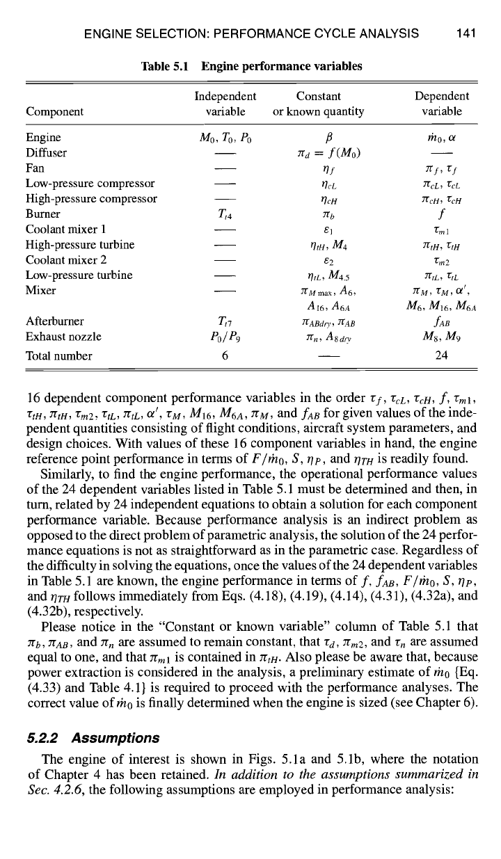
16 dependent component performance variables in the order rf,
rcL, r.cH,
f,
rml,
rtH, zrtH, rm2, rtC, ZrtL, Or', rM, MI~, M6A, zrM, and fAB
for given values of the inde-
pendent quantities consisting of flight conditions, aircraft system parameters, and
design choices. With values of these 16 component variables in hand, the engine
reference point performance in terms of
F/rho, S, tip,
and tire/is readily found.
Similarly, to find the engine performance, the operational performance values
of the 24 dependent variables listed in Table 5.1 must be determined and then, in
turn, related by 24 independent equations to obtain a solution for each component
performance variable. Because performance analysis is an indirect problem as
opposed to the direct problem of parametric analysis, the solution of the 24 perfor-
mance equations is not as straightforward as in the parametric case. Regardless of
the difficulty in solving the equations, once the values of the 24 dependent variables
in Table 5.1 are known, the engine performance in terms of
f, fAB, F/mo, S, tie,
and tirH follows immediately from Eqs. (4.18), (4.19), (4.14), (4.31), (4.32a), and
(4.32b), respectively.
Please notice in the "Constant or known variable" column of Table 5.1 that
Tgb, gAB,
and zr, are assumed to remain constant, that "Cd, 7rm2 , and rn are assumed
equal to one, and that 7gml is contained in rrtH. Also please be aware that, because
power extraction is considered in the analysis, a preliminary estimate of rn0 {Eq.
(4.33) and Table 4.1} is required to proceed with the performance analyses. The
correct value of rn0 is finally determined when the engine is sized (see Chapter 6).
5.2.2 Assumptions
The engine of interest is shown in Figs. 5.1a and 5.1b, where the notation
of Chapter 4 has been retained.
In addition to the assumptions summarized in
Sec. 4.2.6,
the following assumptions are employed in performance analysis: