Mattingly J.D., Heiser W.H., Pratt D.T. Aircraft Engine Design
Подождите немного. Документ загружается.

142 AIRCRAFT ENGINE DESIGN
1) The flow areas are constant at stations 4, 4.5, 6, 16, 6A, and 8 dry (afterburner
off).
2) The flow is choked at the high-pressure turbine entrance nozzles (choking
area 4), at the low-pressure turbine entrance nozzles (choking area 4.5), and at the
exhaust nozzle (station 8). Because the exhaust nozzle may unchoke at low throttle
settings and affect the fan operating line (see Fig. 7.E 10), the case of the unchoked
exhaust nozzle (station 8) is also included in this analysis.
3) The component efficiencies
(Of, OcL, OcH, Oh, OtH, rltL, 1TAB, OmL, rlml-l, ~]mPL,
and
rlmeH)
and total pressure ratios (rOb, Zrgmax,
rCaBary,
and rrn) do not change
from their design values.
4) Bleed air and cooling air fractions are constant. Power takeoffs are constant.
5) The air and combustion gases are modeled as perfect gases in thermody-
namic equilibrium, and their properties are based on the NASA Glenn thermo-
chemical data and the Gordon-McBride equilibrium algorithm reference, s
6) The simplifying gas model of a calorically perfect gas is included in the
analysis. It assumes that the gases are calorically perfect upstream and downstream
of the bumer and afterburner and values of gt,
Cpt, FAB, and CpZ B
do not vary with
throttle setting, but included is the variation of g and
Cp
due to mixing with bypass
ratio. For this model, fuel-air ratios f and
faB are
ignored when compared with
unity.
7) The exit
area A9
of the exhaust nozzle is adjustable so that the pressure ratio
Po/P9
can be set to a predetermined value.
8) The area at each engine station is constant. However the area of station 8
changes with the afterburner setting to maintain constant pressure at the mixer exit
or nozzle entrance.
9) The diffuser total pressure ratio, 7rd, is given by Eqs. (4.12a-4.12d).
5.2.3 Referencing and the Mass Flow Parameter (MFP)
Two techniques are worthy of discussion at this point to prepare the path for their
efficient and frequent use in the analysis to follow. The first is called referencing
and involves the use of reference point conditions to evaluate constants appearing
in equations for the dependent performance variables. The second exploits the mass
flow parameter, introduced in Sec. 1.9.3, to capitalize on the law of conservation
of mass.
Referencing.
The functional relations for engine cycle analysis are based on
the application of mass, energy, momentum, and entropy considerations to the
one-dimensional steady flow of a perfect gas at an engine reference or off-design
steady state operating point. Thus, if at any off-design point
f(r, zr) = constant
represents a relationship between the two performance variables r and Jr at a steady
state operating point, then the constant can be evaluated at the reference point, so
that
f(r, 7r) =
f(re,
ZrR) = constant
ENGINE SELECTION: PERFORMANCE CYCLE ANALYSIS 143
because f(v, zr) applies to both on-design and off-design points. This technique
for replacing constants with reference point values is used frequently in the per-
formance analysis to follow.
Mass flow parameter.
The mass flow parameter
(MFP)
is defined as the
grouping rn 4~t/Pt
A
that can be written as
MFP-- p----~ V R Pt V T
The static to total pressure and temperature ratios
(P/Pt, T~ Tt) are
functions of the
total temperature of gas, chemical equilibrium properties, and the Mach number.
Thus the mass flow parameter can be written in the following functional form:
FnVr~t -- M. V/-~ P./~ = MFP(M, Tt, f)
(4.24)
MFP-- ~tA V R P,V T
The subroutine RGCOMP that is used to calculate the compressible flow functions
(P/Pt, T/Tt, and MFP)
is given in Appendix F. For the simplifying case of the
calorically perfect gas, the properties
P/Pt, T/Tt,
and
MFP are
given by
T 1 + Y - (1.1)
T, 2
P ( Y- 1M2) #'
= 1 + 2 (1.2)
y+l
~'~ ~/~-t ~/~( 1) 2(1-)/)
MFP-- Pt~--M
l+Y2- M2 (1.3)
5.2.4 Performance of Turbines with~without Coolant Mixers
The first step in determining the performance of the entire engine at conditions
away from the reference point is to analyze the behavior of the high- and low-
pressure turbines. This is greatly expedited by the fact that they are both deliberately
designed to be choked in their entrance stator airfoil or vane passages, and that
the static pressure downstream of the low-pressure turbine is tied to the mixer
entrance conditions. As you will see in the development that follows, this both
restricts turbines to a very narrow range of operation and furnishes us with a
straightforward method of solution. The remainder of the engine performance
analysis flows directly from this step because the turbines, in conjunction with
the throttle setting (i.e., T,4), provide the power for the fan and compressors and
control the fan and compressor mass flows (see Sec. 5.2.5).
The performance (rrt and rt) of a turbine at off-design is primarily determined
by the efficiency and mass conservation relationships. It is shown in Ref. 1 that
zrtH and VtH
remain constant for an uncooled turbine with constant specific heats
(calorically perfect gas). Similarly, as shown below, these ratios can be considered
constant for a cooled turbine with constant specific heats (calorically perfect gas).
144 AIRCRAFT ENGINE DESIGN
When a cooled turbine with variable specific heats is modeled, it is found that Zrtn
and Ttn
vary only slightly with engine operating condition.
It is also shown in Ref. 1 that
7rtL
and
TtL are
constant in an uncooled low-
pressure turbine with calorically perfect gas for a turbofan engine having choked
separate (unmixed) fan and core streams. For a mixed flow turbofan, on the other
hand, these ratios cannot be considered constant because
~rtL
(and hence rtL) must
modulate at off-design conditions to maintain P6 = P16, the Kutta condition, at
the mixer entrance.
Variable specific heats.
Consider a high-pressure turbine with cooling air
fractions el and e2 modeled as in Fig. 5.lb. Let the nozzle throat stations just
downstream of stations 4 and 4.5 be denoted by 4' and 4.5'. With choked flow at
stations 4 t and 4.5', Eq. (4.24) yields, assuming
Pt4 = Pt4'
and
Pt4.5 = Pt4.5,
l~t4' Pt4.5/Pt4
A4.5,
MFP(M4,, Tt4,
f)
rh4.5' T~-~-t4.5/Tt4 a4,
MFP(M4.5,, Tt4.5,
f4.5)
or,
since Y/'m2 = l,
7rJtH = Pt4.4/Pt4
and
rn4.5,
rh4
then
YgtH
[ 1
+
I
/4/4 @ /'hC(E'I +
e2) (el + e2)
= =1+
/h 4 (1 -/5 - el - e2)(1 + f)
(_~l -~_ 82 A I A4, MFP(M4,, Tt4, f)
(1 - fl - el - e2)(1 + f) J A4.5,
MFP(M4.5,,
Tt4.5, f4.5)
(5.1)
where the right-hand side of the equation is essentially constant for the assumptions
of this analysis, namely
An,/A4.5, =
constant, M4, = 1, M4.5, = 1, and constant
bleed and cooling airflow fractions. Since
f
f4.5 = (4.8j)
1 + f + (el + e2)/(1 - fl -- el
--
E2)
then for a specific value of Tt4 and f, Eq. (5.1) can be used to calculate Jrtn for an
assumed value of Tt4.5.
Likewise, for given values of
Tt4, f, rrtn,
and Orn, the resultant turbine exit
temperature (Tt4.5) can be determined as follows:
1) The total enthalpy at state t4.1(ht4.1) follows from that at state
t4(ht4)
and
the total enthalpy ratio of coolant mixer 1 (rml).
~rn l
and
ht4.1
ht4.1 = ht4~-'- = ht4"~ml
nt4
where r,,i is given by
(1 - fl - el - e2)(1
+ f) + elrrrcLrcH/rX
(1 -/3 - el - e2)(1 + f) +
el
f
(5.2a)
(4.20a)
f4.1 = (4.8i)
1 + f + el/(1 -- 13
- s1 -
S2)
ENGINE SELECTION: PERFORMANCE CYCLE ANALYSIS 145
2) With state t4.1 known and using Eq. (4.9d), the reduced pressure at the ideal
exit state
t4.4i (Pr
t4.4i)
follows from its value at state t4.1 (Pr t41) and the turbine
total pressure ratio (zrtH).
Pr t4.4i ~-- ~tHPr
t4.1
(4.9d)
3) With
Prt4.4i
known and noting that f4.4 =
f4.1,
then
ht4.4 i
is known using
the subroutine FAIR. The total enthalpy ratio of the ideal turbine (rim) follows
directly using its definition
rtHi = ht4.4i/ ht4.1
(4.9d)
4) By the assumption of constant efficiency of the high-pressure turbine,
Eq. (4.9d) can be solved for the high-pressure turbine enthalpy ratio
(rtn)
~tH
=
1 - rhn(1
-
"CtHi)
(5.2b)
5) With the total enthalpy ratio of coolant mixer 2 (rm2) given by
(1 - ~6 -- el - e2)(1 + f) + el +
e2{rrrcHrcL/(rZ'rmlrtit)}
rm2 = (4.20b)
(1 -/3 - el - e2)(1 + f) +
E1 n t-
e2
and f4.5 given by Eq. (4.8j), the total enthalpy at station 4.5 (ht4.5) can be calculated
using
ht4.5 = ht4
hJ 4"1
ht4"4 ht4"----~5 - ht4rml'Ctnrm2
(5.2c)
t'It4 ht4.1 ht4.4
6) With
ht4.5
and f4.5 known,
Tt4.5
follows directly using the subroutine FAIR.
We will refer to this system of equations used to determine
Tt4.5
as Eq. (5.2).
Equations (5.1) and (5.2) give us a system of equations to satisfy that determine
the high-pressure turbine performance
rtH and rctH.
This system of equations is
programmed into the cooled turbine subroutine TURBC outlined in Appendix E
Subroutine TURBC solves this system by first assuming an initial value of
Tt4.5
and using Eq. (5.1) to find ~rtH. Using this value of zrtH, Eq. (5.2) gives a new
value of total temperature at station 4.5 called
Tt4.5,.
This new value is input into
Eq. (5.1) and calculations are repeated until successive values are within 0.01.
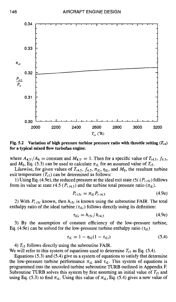
Figure 5.2 shows the variation of rrtn with throttle setting
(Tt4)
for a typical mixed
flow turbofan engine. Note that
7rtn
only varies 0.9%, which shows the common
assumption used in the constant specific heat analysis that
zrtrl
= constant is a very
good approximation.
A similar, but simpler, set of equations can be solved for the uncooled low
pressure turbine. Writing Eq. (5.1) for the low-pressure turbine gives
rrtL A4.5, MFP(M4.5,,
Tt4.5,
f4.5)
,V/~/Tt4.5
A5 MFP(M5, Tt5,
f4.5)
Because the flow is assumed to be isentropic from engine station 5 to station 6 and
we know the area at station 6, we use the Mach number and area at engine station
6 for the low-pressure turbine exit and write
YrtL
A4.5'
MFP(M4.5,, Tt4.5,
f4.5)
(5.3)
~¢/~/Tt4.5 A6 MFP(M6, Tt5,
f4.5)
146 AIRCRAFT ENGINE DESIGN
et4.5
e,4
0.34
0.33
0.32
0.31
' I I I I
Fig. 5.2 Variation of high pressure turbine pressure ratio with throttle setting
(Tt4)
for a typical mixed flow turbofan engine.
where
A4.5,/A6
---- constant and M4.5, = 1. Then for a specific value of
Tt4.5,
f4.5,
and M6, Eq. (5.3) can be used to calculate :rtL for an assumed value of
Tts.
Likewise, for given values of Tt4.5, f4.5, 7rtL, ~tL, and Mo, the resultant turbine
exit temperature (Tts) can be determined as follows:
1) Using Eq. (4.9e), the reduced pressure at the ideal exit state
t5i (Pr tsi)
follows
from its value at state t4.5
(Pr
t4.5) and the turbine total pressure ratio (TrtL).
Pr t5i : 3TtL Pr
t4.5
(4.9e)
2) With
Pr
t5i
k_rlown,
then
ht5i
is known using the subroutine FAIR. The total
enthalpy ratio of the ideal turbine (~Li) follows directly using its definition:
"~tLi : ht5i / ht4.5
(4.9e)
3) By the assumption of constant efficiency of the low-pressure turbine,
Eq. (4.9e) can be solved for the low-pressure turbine enthalpy ratio (rtD
rtt = 1 - tilL(1
-- "CtLi)
(5.4)
4) Tt5 follows directly using the subroutine FAIR.
We will refer to this system of equations used to determine Tt5 as Eq. (5.4).
Equations (5.3) and (5.4) give us a system of equations to satisfy that determine
the low-pressure turbine performance rrtL and rtL. This system of equations is
programmed into the uncooled turbine subroutine TURB outlined in Appendix E
Subroutine TURB solves this system by first assuming an initial value of
Tts
and
using Eq. (5.3) to find ZrtL. Using this value of :rtt, Eq. (5.4) gives a new value of
0.30 = i i I i
2000 2200 2400 2600 2800 3000 3200
T~ 4 (°R)
ENGINE SELECTION: PERFORMANCE CYCLE ANALYSIS 147
total temperature at station 5 called
Tthn.
This new value is input into Eq. (5.3),
and calculations are repeated until successive values are within 0.01.
Constant specific heats.
In the case of a perfect gas with constant specific
heats [calorically perfect gas (CPG)], the equations that model the performance of
the high-pressure and low-pressure turbines are simplified. The mass flow para-
meter for a CPG is given by Eq. (1.3). Since the
MFP
is the same at stations 4' and
4.5' when
M4, : M4.5' =
1, Y4'
: Y4.5' ~---
~/t, and
R4' = R4.5' -----
gt,
then Eq. (5.1)
becomes
7Z't/4 --{1+
(81q"82)
} aA~4'~ (5.1-CPG)
(1
-- ~ --71
--~-2)(1 + f)
za4.5'
where
A4'
= constant
A4.5,
and where, by the assumptions of Sec. 5.2.2,
(El + E2)
1 + = constant
(1
- 13 - 81 - e2)(1 + f)
and where, combining Eqs. (4.20a) and (4.20b),
rmlrm2 = 1 + (1 -~ -el - e2)(1 +f).] (1 -~ --e-i ~- e-2)(1 +f)
(5.1 b-CPG)
Consider the order of magnitude of the second term in the numerator of
Eq. (5. lb-CPG) compared with unity. Noting that, for the performance operation
of interest,
7JtH ~
0.85 and
r~. -- cptTt4 ~
2 ---> 4
12r12cL12cH Cpc Tt3
the second term in the numerator of Eq. (5. lb-CPG) will be of the order of e or less
and its variation at engine off-design can be considered small in comparison with
unity. The denominator is constant, whence the product
72mllhm2
can be considered
constant and Eq. (5.1-CPG) becomes
712tH
-- constant (5.1c-CPG)
when e is an order of magnitude less than unity.
For a calorically perfect gas, Eq. (5.2b) can be written as
"CtH : 1 -- thrill -- 7r~H Y'-I)/y' }
and, by the assumption of constant efficiency of the high-pressure turbine, can be
rewritten as
1 -- "~tn
(e,-1)/y, -- r/tH = constant (5.2b-CPG)
1 - 7rtH
148 AIRCRAFT ENGINE DESIGN
To satisfy both Eqs. (5. lc-CPG) and (5.2b-CPG), the total pressure ratio and the
total temperature ratio of the high-pressure turbine must be constant, or
2"gtH ~
constant
75tH ~
constant
When the same order of magnitude analysis used with Eq. (5. lb-CPG) is applied
to Eqs. (4.20a) and (4.20b) separately for rml and rm2, the coolant mixer total
temperature ratios are found to be approximately constant, or
rml = constant
Z'm2 ~
constant
For the low-pressure turbine with a CPG and M4.5 = 1, Eq. (5.3) can be written
as
• y~+l
{ ( 62)/"'"
~rtL A4.y 1 2 ?'t -- 1 M (5.3-CPG)
A6M y-T 1+ 2
where
A4.5, / A 6 =
constant
Likewise, Eq. (5.4) can be written as
(×,-b/×,
/
rtL = 1 -- OtL{ 1 -- ZrtL I
and, by the assumption of constant efficiency of the low-pressure turbine, can be
rewritten as
1 - "(tL
(×,-1)/×, -- OtL
= constant (5.4-CPG)
1
- 7rtL
For a given value of the Mach number at station 6 (M6) and the constant values of
the area ratio
(A4.5,/A6)
and the turbine efficiency (rhD, there is only one set of
low-pressure turbine total properties (rtL,
rCtL)
that satisfies both Eqs. (5.3-CPG)
and (5.4-CPG).
5.2.5 Component Performance Analysis
The performance of the mixed flow turbofan engine in Figs. 5.1a and 5.1b
can now be analyzed using the assumptions of Sec. 5.2.2 and the techniques of
Secs. 5.2.3 and 5.2.4. The goal is to obtain the 24 independent equations required
to determine the dependent performance variables of Table 5.1. To underscore the
logic of the iteration solution sequence that follows in Sec. 5.2.6, the required equa-
tions will be developed in the order that each arises in the solution flowcharts of
Figs. 5.3a and 5.3b. The equations to be developed next are represented in turn by
the following 24 functional relationships between the 24 dependent performance
ENGINE SELECTION: PERFORMANCE CYCLE ANALYSIS 149
A)
Calculate new
value of a'
using Newtonian
iteration
Initial values of f,a', M6, M 8 , th o
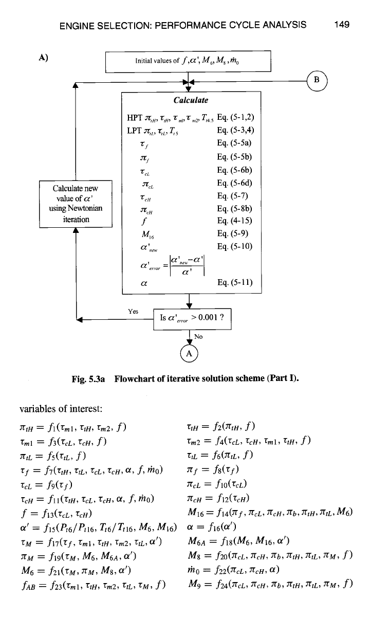
Fig. 5.3a
Calculate
HPT ~,, rtn, ~:ml, r.,2' T,4.5 Eq. (5-1,2)
LPT ~,L, "r,L, T,s Eq. (5-3,4)
~r s Eq. (5-5a)
~j Eq. (5-5b)
~'~L Eq. (5-6b)
:rL Eq. (5-6d)
"t'cH Eq. (5-7)
~H Eq. (5- 8b)
f Eq. (4-15)
M~6 Eq. (5-9)
a ',e,' Eq. (5-10)
, _ a'°ew-a'l
a er~o~ --
a Eq. (5-11)
' > 0.001 9
Yes
Is
~ error "
~
O
Flowchart of iterative solution scheme (Part I).
©
variables of interest:
Zrtn = fl(Zml, rtn, Tin2, f)
Zml = f3(rcL, rcn, f)
ZrtC = fs(rtL, f)
Tf = f7(rtH, rtL, TcL, rcn, Ol, f, l~lo)
"rcL
= f9(rf)
rcH = fll(rtH, rcL, r.cH, Or, f, fnO)
f = f13(rd,,
ZcH)
Ol t = f l5( Pt6/ Ptl6, Tt6/ Ttl6, m6,
m16)
rM = fl7('gf, "gml,
~TtH, rm2, rtL, O lt)
ZrM = fl9(rM, M6,
M6A, or')
M6 = f21(rM, JrM, M8,
a')
fAB =
f23('~ml,
rtn, rm2, rtL, rM, f)
rtH = f2(zrtu, f)
rm2 =
f4(rcL,
rcm rml, r~n, f)
r,/~ = f6(~r,L, f)
~rl = f8(rD
zr~L = flo(r~D
~r~/ = flz(r~H)
M16 = f14(:rrf,
~rcL, 7rcH, Zrb, 7rtn, ZrtL,
M6)
a = fl6(Ot')
M6A =
fls(M6, MI6, o~ t)
M8 = f20(zrcL, ZrcH, 7rb, zr,n, zrtL, JrM, f)
rho = fz2(ZrcL, zr~/~, a)
M9 = f24(TrcL, zr~H, Zrb, :r,m zrtL, rrM, f)
150
B)
AIRCRAFT ENGINE DESIGN
If M 6 > M 6"ew then
M 6 = M 6 -0.0001
else
M 6 =M 6 +0.002
I Yes
z" M Eq. (5-12)
M6A Eq. (5-13)
~M Eq. (5-14)
M8 Eq. (5-15)
M6,,e w
Eq. (5-16)
M
.......
=IM6,e~.-M6[
Is M 6 ..... > 0.0005 ?
No
rh 0 ..... Eq. (5-17)
t~/0new --~/o
th0error =
Is rn o ..... > 0.001 ?
No
Remainder of Calculations
(Appendix I)
Yes
?nO = mo new
Is an engine control limit (~., ~ Reduce
Tt4 ]
/
Tt3, Pt3, etc.) exceeded?
I t
J
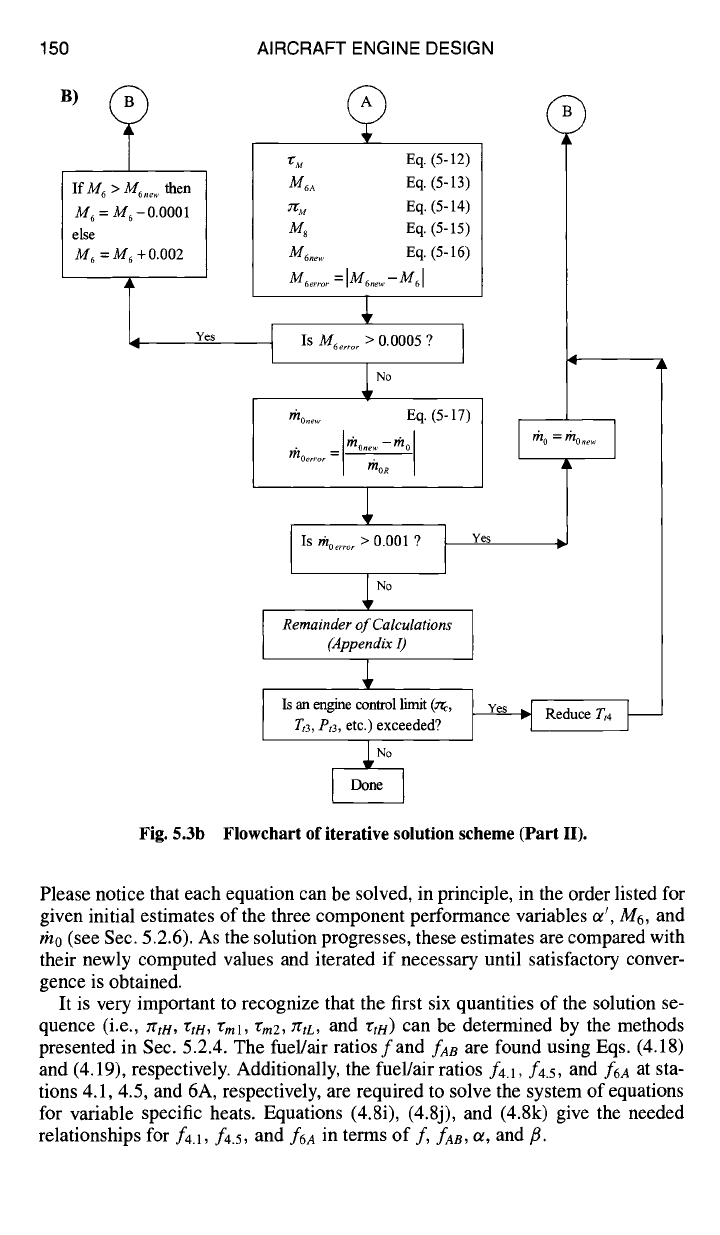
Fig. 5.3b Flowchart of iterative solution scheme (Part II).
Please notice that each equation can be solved, in principle, in the order listed for
given initial estimates of the three component performance variables or', M6, and
rn0 (see Sec. 5.2.6). As the solution progresses, these estimates are compared with
their newly computed values and iterated if necessary until satisfactory conver-
gence is obtained.
It is very important to recognize that the first six quantities of the solution se-
quence (i.e.,
rCt~l, rtH,
~'ml, "gm2,
~tL,
and
rtH ) can
be determined by the methods
presented in Sec. 5.2.4. The fuel/air ratiosfand
fAB are
found using Eqs. (4.18)
and (4.19), respectively. Additionally, the fuel/air ratios faA, f4.5, and
f6a
at sta-
tions 4.1, 4.5, and 6A, respectively, are required to solve the system of equations
for variable specific heats. Equations (4.8i), (4.8j), and (4.8k) give the needed
relationships for f4.1, f4.5, and
f6a
in terms of
f, faB, Or, and ft.
ENGINE SELECTION: PERFORMANCE CYCLE ANALYSIS 151
Fan temperature ratio
(rt)
and low-pressure compressor temperature
ratio
(rcL). From the low-pressure spool power balance, we have
rtL = 1--
rr{(rcC - 1) + u(rf - 1)} + (1 +
ot)CToL/rlmPL
rlmnrXrta{(1
-- fl -- el -- 62)(1 + f) + (el +
F-.2/'EtH)'Er'~cLTEcH/~3.}
which can be rearranged to yield
rf=l+
(1--'CtL)rlmL{th~'4CC r:x'rtH+(61"~tH-I-62)'ccL~:cH }rr
(4.22a)
(1 + ot ) PTOL
~r OmPL rhoho
{(rcL -- 1)/(rf -- 1) + Or}
where, from Fig. 4.2,
th4/thc =
(1 -/~ - el - 62)(1 + f)
Because the low-pressure compressor and the fan are on the same shaft, it
is reasonable to assume that the ratio of the enthalpy rise across the fan to the
enthalpy rise across the low-pressure compressor is constant. Using referencing,
we can therefore write
htl3 --ht2 ~f -- 1 (Tf --
1)R
ht2.5
--ht2
"EcL- 1 (Z'cL --
1)R
Thus the fan enthalpy ratio can be written as
~:f = 1+
{ r~t4
"E~"CtH _1¢_
(,Sl-Ct H ..1- e2)-CcLr;cH}
(1
+ or)
PTOL
(1-- rtL)TlmL I'h C r''~ rrrlmPL fnoho
{(ZcL -- 1)R/(rf --
1)R
+ or}
(5.5a)
and the low-pressure compressor enthalpy ratio can be written as
rcL = 1 + (zf -
1)[(ZcL --
1)g/(rf --
1)R] (5.5b)
For a calorically perfect gas, h0 =
cpcTo
in Eq. (5.5a) and Eq. (5.5b) is
unchanged.
Fan pressure ratio (~f) and low-pressure compressor pressure ratio
(~cL),
From the definition of fan efficiency, Eq. (4.9a),
htl3i =
ht2{1 q-
rlf('gf --
1)} (5.6a)
Given
htl3i ,
the subroutine FAIR will give the reduced pressure
Pr tl3i.
Thus the
fan pressure ratio is calculated using Eq. (4.9a) written as
ert
13i
(5.6b)
~ f -- Pr t2
Likewise, from the definition of low-pressure compressor efficiency, Eq. (4.9b),
ht2.fi
=
ht2{1 +
17cL(ZcL --
1)} (5.6c)