Mattingly J.D., Heiser W.H., Pratt D.T. Aircraft Engine Design
Подождите немного. Документ загружается.

172 AIRCRAFT ENGINE DESIGN
40 kft
7
Compressor
Pressure
Ratio (z~)
6
3 J L ~ L I ~ ~ i ~ I ~ , , , I ~ ~ , ,
0.0 0.5 1.0 1.5
M0
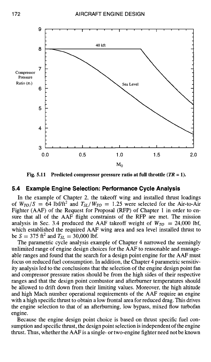
Fig. 5.H Predicted compressor pressure ratio at full throttle
(TR
=
]).
2.0
5.4 Example Engine Selection: Performance Cycle Analysis
In the example of Chapter 2, the takeoff wing and installed thrust loadings
of
WTo/S
= 64 lbf/ft 2 and
TsL/Wro
= 1.25 were selected for the Air-to-Air
Fighter (AAF) of the Request for Proposal (RFP) of Chapter 1 in order to en-
sure that all of the AAF flight constraints of the RFP are met. The mission
analysis in Sec. 3.4 produced the AAF takeoff weight of
WTO
= 24,000 lbf,
which established the required AAF wing area and sea level installed thrust to
be S = 375 ft 2 and
TsL
= 30,000 lbf.
The parametric cycle analysis example of Chapter 4 narrowed the seemingly
unlimited range of engine design choices for the AAF to reasonable and manage-
able ranges and found that the search for a design point engine for the AAF must
focus on reduced fuel consumption. In addition, the Chapter 4 parametric sensitiv-
ity analysis led to the conclusions that the selection of the engine design point fan
and compressor pressure ratios should be from the high sides of their respective
ranges and that the design point combustor and afterburner temperatures should
be allowed to drift down from their limiting values. Moreover, the high altitude
and high Mach number operational requirements of the AAF require an engine
with a high specific thrust to obtain a low frontal area for reduced drag. This drives
the engine selection to that of an afterburning, low bypass, mixed flow turbofan
engine.
Because the engine design point choice is based on thrust specific fuel con-
sumption and specific thrust, the design point selection is independent of the engine
thrust. Thus, whether the AAF is a single- or two-engine fighter need not be known
ENGINE SELECTION: PERFORMANCE CYCLE ANALYSIS 173
until the engine is sized. When the engine is sized, however, in Chapter 6, the
number of engines must be specified by the airframe and propulsion design teams.
With the detailed results of the preceding examples and the parametric
(on-design) and performance (off-design tools) embedded in the textbook's com-
puter programs ONX and AEDsys, the systematic search begun in Chapter 4 for
an optimum combination of engine design choices that satisfy the AAF mission
requirements will now be extended. In the search here, the influence of each of
the design parameters on the engine performance at the off-design critical flight
conditions of the mission is determined. The goal is to find the best combination
of design choices for the AAF engine. The search is well on its way as a result of
the extensive work accomplished in Sec. 4.4.
5.4.1 Critical Flight Conditions
The first engine to be selected in the search for the optimum AAF design point
engine will serve as the baseline engine. The performance of this engine over the
critical legs of the mission forms a basis for comparison of other engine candidates.
It is necessary at the outset, therefore, to establish which mission legs are to be
judged as critical for the search. Any leg that 1) has a high fuel consumption
(low Iq) as determined from Table 3.E3 and Sec. 3.4.4; 2) represents a boundary
of the solution space in the revised constraint diagram of Fig 3.E5; or 3) is an
extreme operating condition should be considered critical. Based on these criteria,
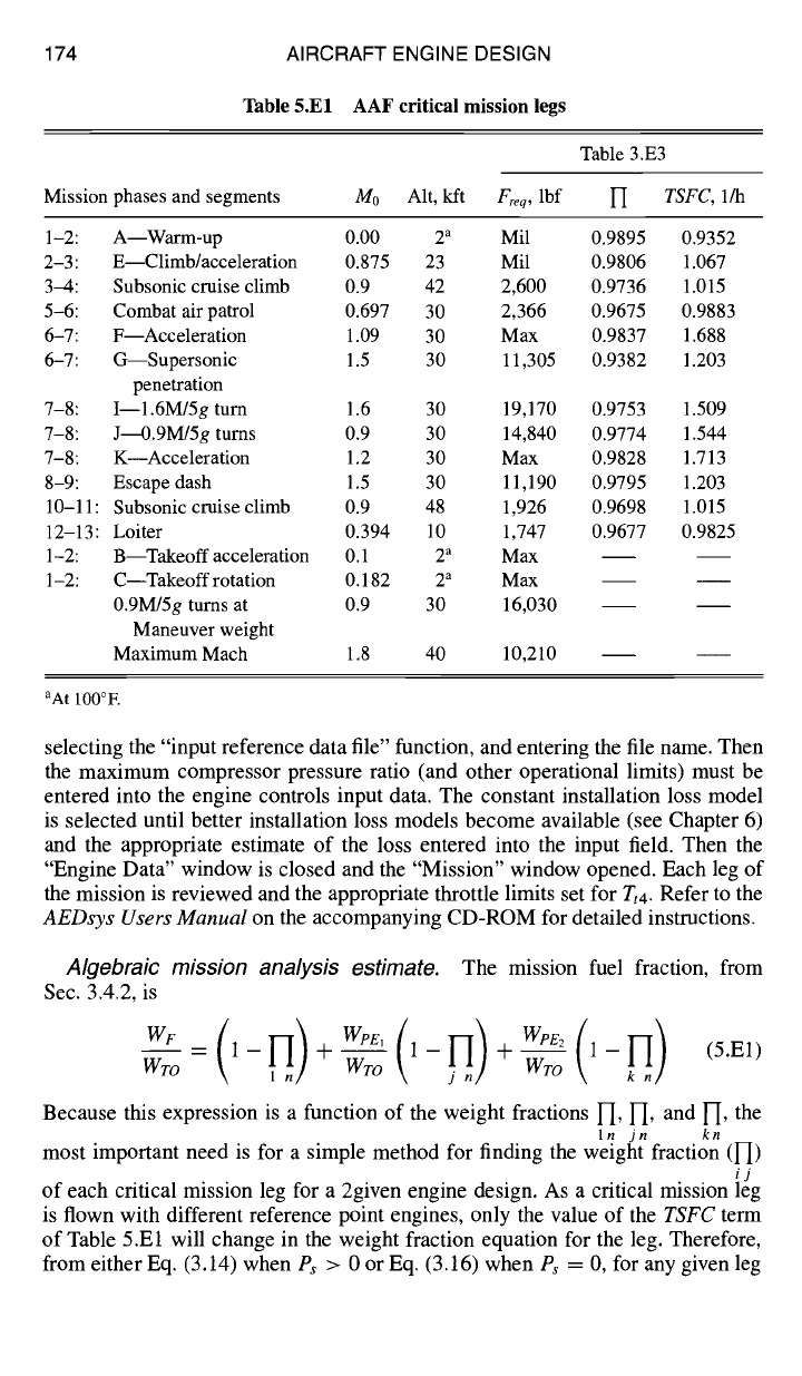
the flight conditions listed in Table 5.El are considered critical for this study. The
power setting or, if the leg is at constant speed, the required uninstalled thrust
[Freq
= D/0.95, allowing in Eq. (6.1) for 5% installation losses] is given in the
table for each mission leg listed. The required thrust can be used in the AEDsys
performance analysis to find the requisite throttle setting (i.e.,
Tt4
and TtT) for type
B, Ps
= 0 legs. The weight fraction and the estimated installed thrust specific fuel
consumption
(TSFC)
obtained in Sec. 3.3 are also listed for those legs considered
fuel critical. The last four legs given in the table represent the takeoff constraint
boundary limit, Combat Turn 2 constraint (0.9/30 kft, 5g), and the maximum Mach
number extreme operating condition.
5. 4.2 Mission Fuel Consumption
Mission fuel usage plays a dominant role in the selection of the AAF engine
design. There are two methods for calculating the fuel used: 1) the mission analysis
portion of the AEDsys computer program, or 2) an estimate based on the algebraic
analysis of Sec. 3.4.2.
Computer calculated mission analysis.
Based on an input takeoff weight,
the mission analysis portion of the AEDsys computer program flies the aircraft
and reference point engine through the mission and determines the fuel used for
each leg and the overall fuel used. This powerful tool includes the engine per-
formance engine model described in this chapter. All you need to do to begin is
design an engine using the ONX computer program's "single point" calculation
capability and save the resulting reference engine as a reference data file (*.REF).
The reference data file is then input into the AEDsys program by selecting "Cycle
Deck" from the Engine pull-down menu (or opening the "Engine Data" window),
174 AIRCRAFT ENGINE DESIGN
Table 5.El AAF critical mission legs
Mission phases and segments
Table 3.E3
M0 Alt, kft
Freq,
lbf
1-'[ TSFC, 1/h
1-2: A--Warm-up 0.00 2 a Mil 0.9895 0.9352
2-3: E--Climb/acceleration 0.875 23 Mil 0.9806 1.067
3-4: Subsonic cruise climb 0.9 42 2,600 0.9736 1.015
5-6: Combat air patrol 0.697 30 2,366 0.9675 0.9883
6-7: F--Acceleration 1.09 30 Max 0.9837 1.688
6-7: G--Supersonic 1.5 30 11,305 0.9382 1.203
penetration
7-8: I--1.6M/5g turn 1.6 30 19,170 0.9753 1.509
7-8: J----O.gM/5g turns 0.9 30 14,840 0.9774 1.544
7-8: K Acceleration 1.2 30 Max 0.9828 1.713
8-9: Escape dash 1.5 30 11,190 0.9795 1.203
10-11: Subsonic cruise climb 0.9 48 1,926 0.9698 1.015
12-13: Loiter 0.394 10 1,747 0.9677 0.9825
1-2: B--Takeoff acceleration 0.1 2 a Max
1-2: C--Takeoff rotation 0.182 2 a Max
0.gM/5g turns at 0.9 30 16,030
Maneuver weight
Maximum Mach 1.8 40 10,210
aAtl00°F.
selecting the "input reference data file" function, and entering the file name. Then
the maximum compressor pressure ratio (and other operational limits) must be
entered into the engine controls input data. The constant installation loss model
is selected until better installation loss models become available (see Chapter 6)
and the appropriate estimate of the loss entered into the input field. Then the
"Engine Data" window is closed and the "Mission" window opened. Each leg of
the mission is reviewed and the appropriate throttle limits set for Tt4. Refer to the
AEDsys Users Manual
on the accompanying CD-ROM for detailed instructions.
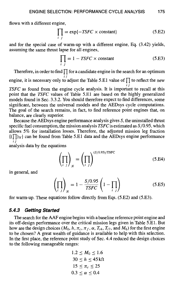
Algebraic mission analysis estimate.
The mission fuel fraction, from
Sec. 3.4.2, is
WF
1-- +-- 1-- +-- 1-- (5.El)
WTO Wro Wro
Because this expression is a function of the weight fractions l-i, l-i, and l-I, the
In jn kn
most important need is for a simple method for finding the weight fraction (I-[)
ij
of each critical mission leg for a 2given engine design. As a critical mission leg
is flown with different reference point engines, only the value of the
TSFC
term
of Table 5.El will change in the weight fraction equation for the leg. Therefore,
from either Eq. (3.14) when Ps > 0 or Eq. (3.16) when
Ps
= 0, for any given leg
ENGINE SELECTION: PERFORMANCE CYCLE ANALYSIS 175
flown with a different engine,
H = exp{-TSFC x constant} (5.E2)
ij
and for the special case of warm-up with a different engine, Eq. (3.42) yields,
assuming the same thrust lapse for all engines,
U = 1 - TSFC x constant (5.E3)
ij
Therefore, in order to find 1-[ for a candidate engine in the search for an optimum
ij
engine, it is necessary only to adjust the Table 5.El value of l--[ to reflect the new
ij
TSFC as found from the engine cycle analysis. It is important to recall at this
point that the TSFC values of Table 5.El are based on the highly generalized
models found in Sec. 3.3.2. You should therefore expect to find differences, some
significant, between the universal models and the AEDsys cycle computations.
The goal of the search remains, in fact, to find reference point engines that, on
balance, are clearly superior.
Because the AEDsys engine performance analysis gives S, the uninstalled thrust
specific fuel consumption, the mission analysis TSFC is estimated as S/0.95, which
allows 5% for installation losses. Therefore, the adjusted mission leg fraction
{(I-DN} can be found from Table 5.El data and the AEDsys engine performance
ij
analysis data by the equations
N \i j/
in general, and
1
N
for warm-up. These equations follow directly from Eqs. (5.E2) and (5.E3).
(5.E4)
(5.E5)
5.
4.3 Getting Started
The search for the AAF engine begins with a baseline reference point engine and
its off-design performance over the critical mission legs given in Table 5.El. But
how are the design choices (M0, h, zrc, ~rf, or, Tt4, TtT, and Mr) for the first engine
to be chosen? A great wealth of guidance is available to help with this selection.
In the first place, the reference point study of Sec. 4.4 reduced the design choices
to the following manageable ranges:
1.2<M0< 1.6
30<h<45kft
15 </rc < 25
0.3 <ot<0.4
176 AIRCRAFT ENGINE DESIGN
3<7rf <5
Tt4 ~ 3200°R
T,7 < 3600°R
0.35 < M6 < 0.45
In addition, the conclusions of the sensitivity study of Sec. 4.4.5 indicated that Tgf
and 7rc should be selected from the high ends of their respective ranges, while,
Tt4
and/or To should be allowed to drift down from their limiting values in order to
reduce fuel consumption. Moreover, as shown in Sec. 4.3.4, the selections of 7rc
and 2"/'f are interdependent. Because we will select cycles for which
try ~ ZrcL (5.E6)
then, from Eq. (4.34)
1
7Ccn ~ -- (5.E7)
7rtHTgtL
Finally, because zra4 and zrtL must be less than about 0.5 in order to ensure that the
turbine entrance nozzles are choked, we conclude that
rrd4 > 4 (5.E8)
Simultaneously, note that the requirement that zrtH and
7"gtL
be less than 0.5
requires
"CtH
and rtL to be less than about 0.87 [see Eqs. (4.9d) and (4.9e)]. This
impacts on the selection of try and a because Jrf, or, ra4, and
rtL are
related through
the low pressure spool power balance. As an approximation for the purposes here,
consider the low spool power balance for a turbofan with no bleed air, no turbine
cooling, and no power takeoff. Solving the low-pressure spool power balance
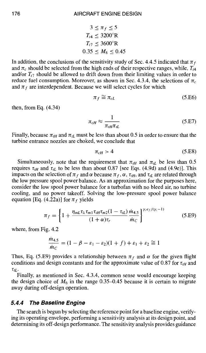
equation [Eq. (4.22a)] for 7rf yields
{ r]mL rgk VSml r:tHTgm2(1-- 72tL) lh4.5 } g'e/ /(Y'-l)
try = 1 + (1 + oe)rr the- (5.E9)
where, from Fig. 4.2
rh4.5
= (1 - fl - el
- e2)(1
+ f) + el + e2 ~ 1
rhc
Thus, Eq. (5.E9) provides a relationship between zrf and a for the given flight
conditions and design constants and for the approximate value of 0.87 for rtH and
r2tL.
Finally, as mentioned in Sec. 4.3.4, common sense would encourage keeping
the design choice of M6 in the range 0.354).45 because it is certain to migrate
away during off-design operation.
5.4.4 The Baseline Engine
The search is begun by selecting the reference point for a baseline engine, verify-
ing its operating envelope, performing a sensitivity analysis at its design point, and
determining its off-design performance. The sensitivity analysis provides guidance
ENGINE SELECTION: PERFORMANCE CYCLE ANALYSIS 177
in selecting subsequent engines to be studied, while the detailed off-design perfor-
mance of the baseline engine will illustrate the off-design analysis to be followed
for other candidate engines in the search. As noted in Sec. 4.2.8, the MSH (Mod-
ified Specific Heat) model is used in all of the ensuing AAF engine performance
calculations.
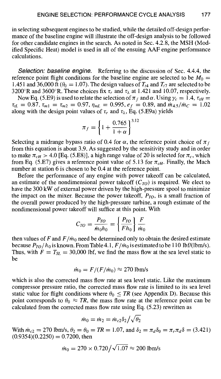
Selection: baseline engine.
Referring to the discussion of Sec. 4.4.4, the
reference point flight conditions for the baseline engine are selected to be M0 =
1.451 and 36,000 ft (00 = 1.07). The design values of Tr4 and
Tt7 are
selected to be
3200°R and 3600°R. These choices fix rr and rz at 1.421 and 10.07, respectively.
Now Eq. (5.E9) is used to relate the selection
ofYr/ande.
Using Fc = 1.4, vtt-/=
rtL =
0.87,
Vml ---- rm2 =
0.97,
OraL =
0.995,
ef
----
0.89, and
lh4.5/tn C
----
1.02
along with the design point values of rr and rz, Eq. (5.E9a) yields
{ 0.765} 3'2
~f=
1 + 1---~
Selecting a midrange bypass ratio of 0.4 for or, the reference point choice of
2Tf
from this equation is about 3.9. As suggested by the sensitivity study and in order
to make
Zrcn
> 4.0 [Eq. (5.E8)], a high range value of 20 is selected for 7rc, which
from Eq. (5.E7) gives a reference point value of 5.13 for erie. Finally, the Mach
number at station 6 is chosen to be 0.4 at the reference point.
Before the performance of any engine with power takeoff can be calculated,
an estimate of the nondimensional power takeoff
(CTo)
is required. We elect to
have the 300 kW of external power driven by the high-pressure spool to minimize
the impact on the mixer. Because the power takeoff,
Pro,
is a small fraction of
the overall power produced by the high-pressure turbine, a rough estimate of the
nondimensional power takeoff will suffice at this point. With
PTO _ I Pr° } F
CTO -- thoh~o [ Fho rh---oo
then values of F and
F/tho
need be determined only to obtain the desired estimate
because
Pro / ho
is known. From Table 4.1,
F/Fno
is estimated to be 110 lbf/(lbm/s).
Thus, with F =
TSL
= 30,000 lbf, we find the mass flow at the sea level static to
be
Fno = F/(F/r'no) ~
270 lbm/s
which is also the corrected mass flow rate at sea level static. Like the maximum
compressor pressure ratio, the corrected mass flow rate is limited to its sea level
static value for flight conditions where 00 <
TR
(see Appendix D). Because this
point corresponds to 00 .-~
TR,
the mass flow rate at the reference point can be
calculated from the corrected mass flow rate using Eq. (5.23) rewritten as
mo = ,h2 =
With rnc2 = 270 Ibm/s, 02 -- 00 =
TR
= 1.07, and 62 = 7rd3o = zrrrra6 = (3.421)
(0.9354)(0.2250) = 0.7200, then
rho = 270 × 0.720/l~/L~.07 ~ 200 lbm/s
178 AIRCRAFT ENGINE DESIGN
Hence, the nondimensional power takeoff, with
Pro
= 300 kW and h0 =
93.72 Btu/lbm
[Cp¢
= 0.24 Btu/(lbm-°R), To = 390.5°R, and h0 =
cpcTo],
is
estimated to be 0.01517 or in round figures, say, 0.0152, which makes
Pro =
300.6 kW ,~ 300 kW.
All engines to be examined in the search will use this design point value of
0.0152 for
Cro. In
addition, the mixer inlet design point Mach number (M6) will
be 0.4 for all engines to be studied.
Please bear in mind the fact that the size or scale of the engine, as represented
here by th0, can and will be easily changed within AEDsys to match the precise
requirements of the aircraft system over the entire mission. Moreover, the scale of
the engine has no effect on any specific performance properties, which includes
the vast majority of the engine cycle quantities of interest.
In summary, the reference point parameters for the baseline engine are as
follows:
M0 = 1.451 2"{f = 3.9
Tt4 =
3200°R
CroH
= 0.0152
h = 36 kft a = 0.4487
Tt7
= 3600°R
zrc = 20 M6 = 0.4 m0 = 200 lbm/s
Note that the bypass ratio has increased from its initial assumed value of 0.4 to
0.4487. This is mainly caused by the decreases in
"CtH
and
TtL
from their assumed
values of 0.87 (see the following).
The reference point performance of this engine at military power is summarized
next. Performance results of particular interest are
F/tho and S.
These and other
data, which are of interest because they are the cumulative result of many approxi-
mations and arguments (Sec. 5.4.3) used as guidance in the selection of the design
choices, are as follows:
F/rho
= 62.49 lbf/(lbm/s)
7rtH = 0.4231 < 0.5
zrtL = 0.4831 < 0.5
rtH = 0.8381 < 0.87
S = 1.0863 (lbm/h)/lbf
7JtL
=
0.8598 < 0.87
et6/ etl6 =
1.0
MI6 = 0.394 ,-~ M6 = 0.4
Operating envelope: baseline engine.
Before examining the performance
of the baseline engine, it is important to first ascertain the Mach number and altitude
ranges over which the engine can operate at full throttle (Tt4max with or without
afterburning), i.e., its full throttle operating envelope. It may come as a surprise at
first that an engine might not be able to operate at certain combinations of Mach
number and altitude. The full throttle Mach number and altitude operational limits
of a mixed flow turbofan engine are caused by the requirement that both the Kutta
condition (P6
= P16)
in the fixed area mixer and the power balance between the
fan plus low-pressure compressor and the low-pressure turbine (which fixes P6)
must be satisfied simultaneously. There are Mach number/altitude combinations
where both of these conditions cannot be met simultaneously, as indicated by the
inability of the Engine Test feature of the AEDsys computer program to converge
on a solution for
MI6
and]or
TtL.
To find these boundaries for the baseline engine, a performance analysis is
performed using the Engine Test feature of the AEDsys program with full throttle
ENGINE SELECTION: PERFORMANCE CYCLE ANALYSIS 179
0.90
0.80
0.70
M6
MI 6
0.60
"E tL
0.50
0.40
0.30 '
0.0
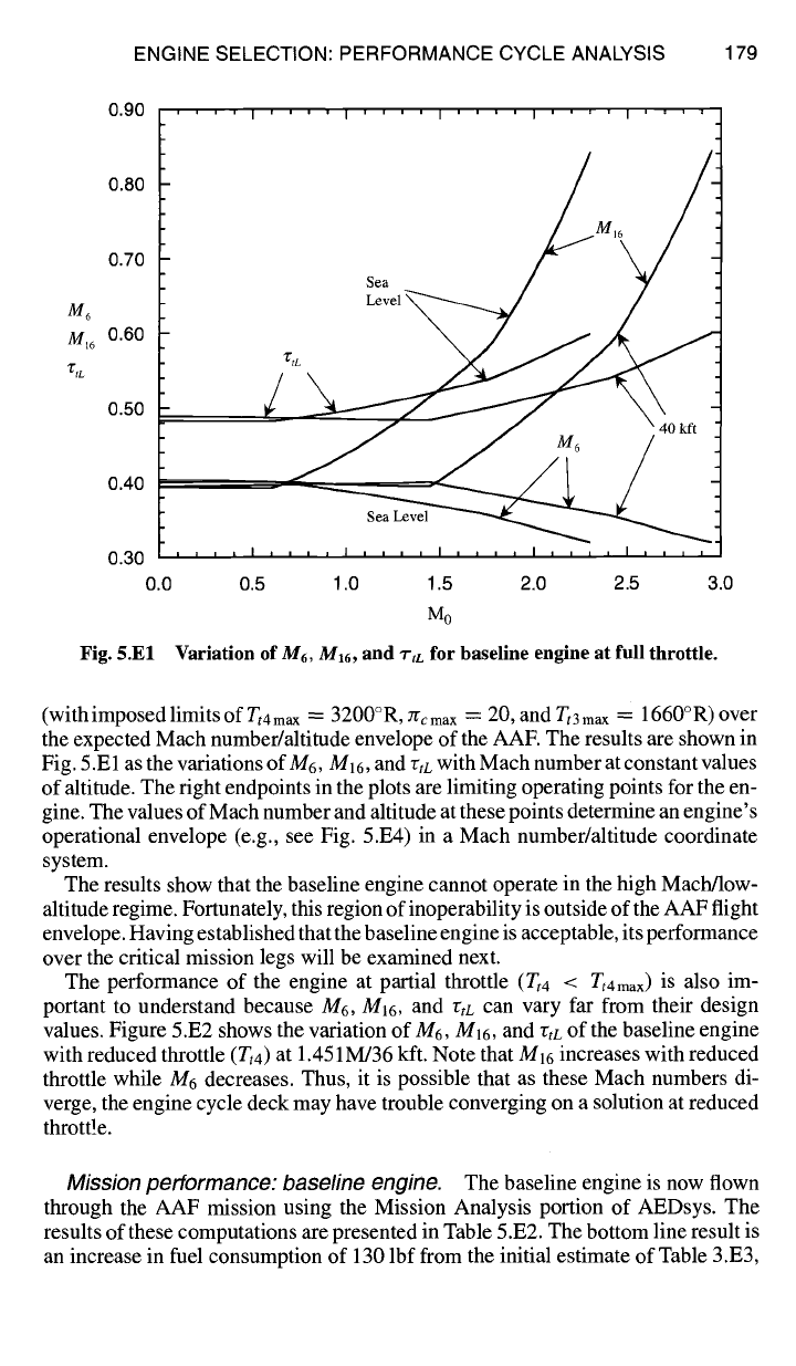
Fig. 5.El
' ' ' ' I ' ' ' ' I ' ' ' ' I ' ' ' ' I ' ' ' '
/
' ' ' r
I
, , , , I , , , , I , , , , I D , , ,
0.5 1.0 1.5 2.0 2.5 3.0
M0
Variation of
M6, M16,
and
"i'tL
for baseline engine at full throttle.
(with imposed limits of Tt4
max m_
3200°R, 7rc
max -~-
20, and T,3
max =
1660°R) over
the expected Mach number/altitude envelope of the AAE The results are shown in
Fig. 5.E 1 as the variations of M6, M]6, and rtL with Mach number at constant values
of altitude. The right endpoints in the plots are limiting operating points for the en-
gine. The values of Mach number and altitude at these points determine an engine's
operational envelope (e.g., see Fig. 5.E4) in a Mach number/altitude coordinate
system.
The results show that the baseline engine cannot operate in the high Mach/low-
altitude regime. Fortunately, this region of inoperability is outside of the AAF flight
envelope. Having established that the baseline engine is acceptable, its performance
over the critical mission legs will be examined next.
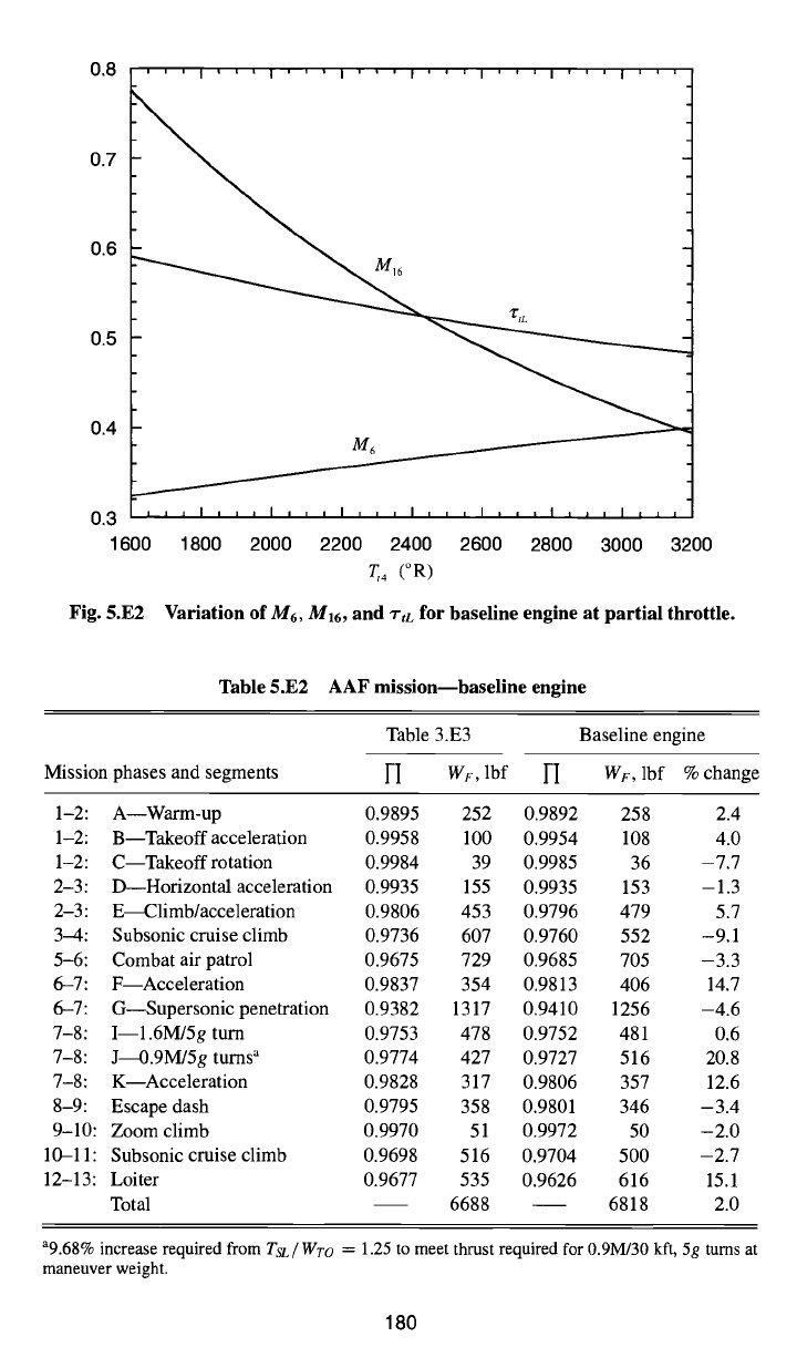
The performance of the engine at partial throttle (Tt4 < Tt4max) is also im-
portant to understand because M6, MI6, and rtc can vary far from their design
values. Figure 5.E2 shows the variation of M6,
M16,
and rtr of the baseline engine
with reduced throttle (Tt4) at 1.451M/36 kft. Note that M16 increases with reduced
throttle while M6 decreases. Thus, it is possible that as these Mach numbers di-
verge, the engine cycle deck may have trouble converging on a solution at reduced
thrott!e.
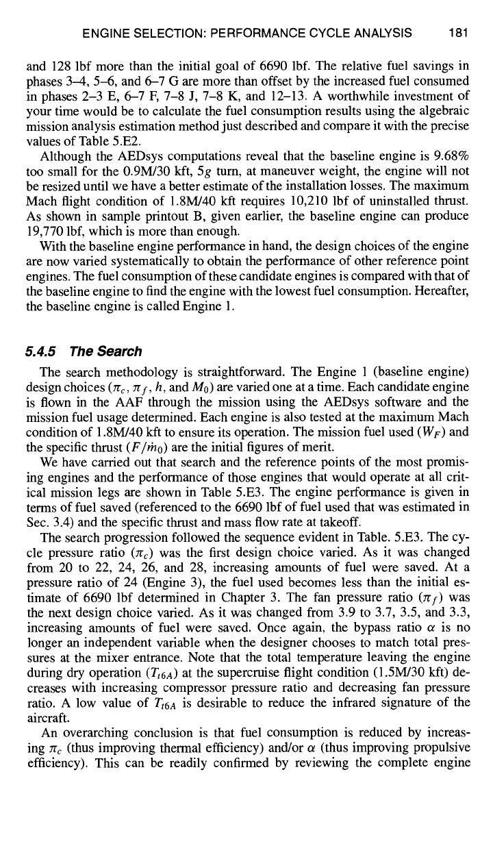
Mission performance: baseline engine. The baseline engine is now flown
through the AAF mission using the Mission Analysis portion of AEDsys. The
results of these computations are presented in Table 5.E2. The bottom line result is
an increase in fuel consumption of 130 lbf from the initial estimate of Table 3.E3,
0.8
0.7
0.6
0.5
0.4
0.3
' I ' I ' ' ' I ' ' ' I ' ' ' I ' ' ' I ' ' ' I ' ' ' I ' ' '
M6
,,,l,,,l,,,l,,,l,,,l,,,llliltl i
1600 1800 2000 2200 2400 2600 2800 3000 3200
~,4 (°R)
Fig. 5.E2 Variation of M6, M16, and ~-tL for baseline engine at partial throttle.
Table 5.E2 AAF mission--baseline engine
Mission phases and segments
Table 3.E3 Baseline engine
l-I WF,
lbf l--I
WF,
lbf % change
1-2: A Warm-up 0.9895 252 0.9892 258 2.4
1-2: B Takeoff acceleration 0.9958 100 0.9954 108 4.0
1-2: C--Takeoff rotation 0.9984 39 0.9985 36 -7.7
2-3: D--Horizontal acceleration 0.9935 155 0.9935 153 -1.3
2-3: E~limb/acceleration 0.9806 453 0.9796 479 5.7
3--4: Subsonic cruise climb 0.9736 607 0.9760 552 -9.1
5-6: Combat air patrol 0.9675 729 0.9685 705 -3.3
6-7: F Acceleration 0.9837 354 0.9813 406 14.7
6-7: G--Supersonic penetration 0.9382 1317 0.9410 1256 -4.6
7-8: I--1.6M/5g turn 0.9753 478 0.9752 481 0.6
7-8: J~.9M/5g turns a 0.9774 427 0.9727 516 20.8
7-8: K--Acceleration 0.9828 317 0.9806 357 12.6
8-9: Escape dash 0.9795 358 0.9801 346 -3.4
9-10: Zoom climb 0.9970 51 0.9972 50 -2.0
10-11: Subsonic cruise climb 0.9698 516 0.9704 500 -2.7
12-13: Loiter 0.9677 535 0.9626 616 15.1
Total 6688 6818 2.0
a9.68% increase required from
TsL/Wro
= 1.25 to meet thrust required for 0.9M/30 kft, 5g turns at
maneuver weight.
180
ENGINE SELECTION: PERFORMANCE CYCLE ANALYSIS 181
and 128 lbf more than the initial goal of 6690 lbf. The relative fuel savings in
phases 3-4, 5-6, and 6-7 G are more than offset by the increased fuel consumed
in phases 2-3 E, 6-7 F, 7-8 J, 7-8 K, and 12-13. A worthwhile investment of
your time would be to calculate the fuel consumption results using the algebraic
mission analysis estimation method just described and compare it with the precise
values of Table 5.E2.
Although the AEDsys computations reveal that the baseline engine is 9.68%
too small for the 0.9M/30 kft, 5g tum, at maneuver weight, the engine will not
be resized until we have a better estimate of the installation losses. The maximum
Mach flight condition of 1.8M/40 kft requires 10,210 lbf of uninstalled thrust.
As shown in sample printout B, given earlier, the baseline engine can produce
19,770 lbf, which is more than enough.
With the baseline engine performance in hand, the design choices of the engine
are now varied systematically to obtain the performance of other reference point
engines. The fuel consumption of these candidate engines is compared with that of
the baseline engine to find the engine with the lowest fuel consumption. Hereafter,
the baseline engine is called Engine 1.
5.4.5 The Search
The search methodology is straightforward. The Engine 1 (baseline engine)
design choices (Jrc, zrf, h, and M0) are varied one at a time. Each candidate engine
is flown in the AAF through the mission using the AEDsys software and the
mission fuel usage determined. Each engine is also tested at the maximum Mach
condition of 1.8M/40 kft to ensure its operation. The mission fuel used (WF) and
the specific thrust (F//no) are the initial figures of merit.
We have carried out that search and the reference points of the most promis-
ing engines and the performance of those engines that would operate at all crit-
ical mission legs are shown in Table 5.E3. The engine performance is given in
terms of fuel saved (referenced to the 6690 lbf of fuel used that was estimated in
Sec. 3.4) and the specific thrust and mass flow rate at takeoff.
The search progression followed the sequence evident in Table. 5.E3. The cy-
cle pressure ratio (Zrc) was the first design choice varied. As it was changed
from 20 to 22, 24, 26, and 28, increasing amounts of fuel were saved. At a
pressure ratio of 24 (Engine 3), the fuel used becomes less than the initial es-
timate of 6690 lbf determined in Chapter 3. The fan pressure ratio (zrf) was
the next design choice varied. As it was changed from 3.9 to 3.7, 3.5, and 3.3,
increasing amounts of fuel were saved. Once again, the bypass ratio ~ is no
longer an independent variable when the designer chooses to match total pres-
sures at the mixer entrance. Note that the total temperature leaving the engine
during dry operation
(Zt6a)
at the supercruise flight condition (1.5M/30 kft) de-
creases with increasing compressor pressure ratio and decreasing fan pressure
ratio. A low value of
Tt6 A
is desirable to reduce the infrared signature of the
aircraft.
An overarching conclusion is that fuel consumption is reduced by increas-
ing zr¢ (thus improving thermal efficiency) and/or ot (thus improving propulsive
efficiency). This can be readily confirmed by reviewing the complete engine