Mattingly J.D., Heiser W.H., Pratt D.T. Aircraft Engine Design
Подождите немного. Документ загружается.

,,,=
==
==
==
=1
¢,
o~
¢-q
~o~
I-
~ I ~ I,~ _
I ~1
I I I I~1 I I i~r i i f~l f i]~ ~ . .._, ~
,._=
I I I I~1 I I I~1 I I I~1 I I I,~
I I I I~1 I I I~-I I I I~1 I I I~-I~
ddddddddddddddddddddddd
E
E
2
;=
,..5
~=
$
H
..j
E
b
182
Fuel
Saved
(lbf~
ENGINE SELECTION: PERFORMANCE CYCLE ANALYSIS 183
300
200
100
-100
-200
20
J
21 22 23 24 25 26 27 28
Compressor Pressure Ratio (~c)
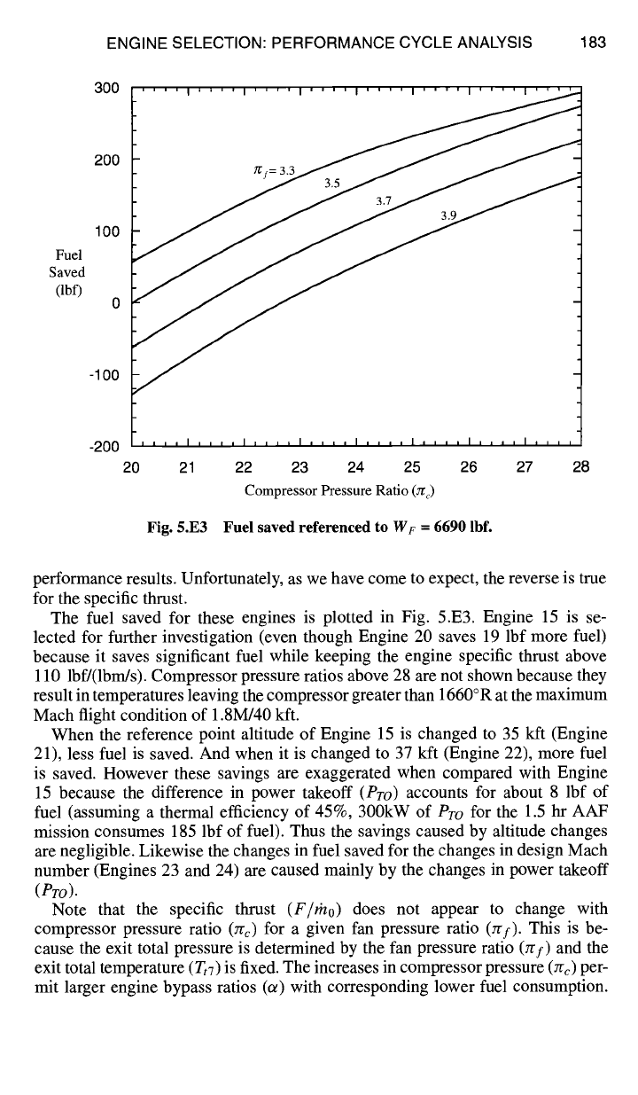
Fig. 5.E3 Fuel saved referenced to Wr = 6690 lbf.
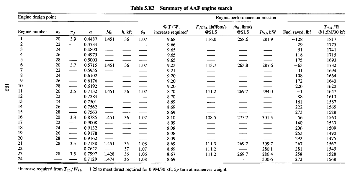
performance results. Unfortunately, as we have come to expect, the reverse is true
for the specific thrust.
The fuel saved for these engines is plotted in Fig. 5.E3. Engine 15 is se-
lected for further investigation (even though Engine 20 saves 19 lbf more fuel)
because it saves significant fuel while keeping the engine specific thrust above
110 lbf/(lbm/s). Compressor pressure ratios above 28 are not shown because they
result in temperatures leaving the compressor greater than 1660°R at the maximum
Mach flight condition of 1.8M/40 kft.
When the reference point altitude of Engine 15 is changed to 35 kft (Engine
21), less fuel is saved. And when it is changed to 37 kft (Engine 22), more fuel
is saved. However these savings are exaggerated when compared with Engine
15 because the difference in power takeoff
(Pro)
accounts for about 8 lbf of
fuel (assuming a thermal efficiency of 45%, 300kW of
Pro
for the 1.5 hr AAF
mission consumes 185 lbf of fuel). Thus the savings caused by altitude changes
are negligible. Likewise the changes in fuel saved for the changes in design Mach
number (Engines 23 and 24) are caused mainly by the changes in power takeoff
(Pro).
Note that the specific thrust
(F/mo)
does not appear to change with
compressor pressure ratio (7rc) for a given fan pressure ratio (~rf). This is be-
cause the exit total pressure is determined by the fan pressure ratio (7~f) and the
exit total temperature (T~7) is fixed. The increases in compressor pressure (~rc) per-
mit larger engine bypass ratios (o0 with corresponding lower fuel consumption.
184 AIRCRAFT ENGINE DESIGN
The Engine 15 design parameters are as follows:
M0 = 1.451 7/'f = 3.5
Tt4 =
3200°R Crow = 0.0152
h = 36 kft c¢ = 0.7563 Tt7 = 3600°R
Zrc = 28 M6 = 0.4 rh0 = 200 lbm/s
The results of the reference point calculations for the Engine 15 engine were
given earlier in sample printout A. Sample printout B and sample printout C give
the performance of this engine at one full throttle and partial throttle operating
condition, respectively.
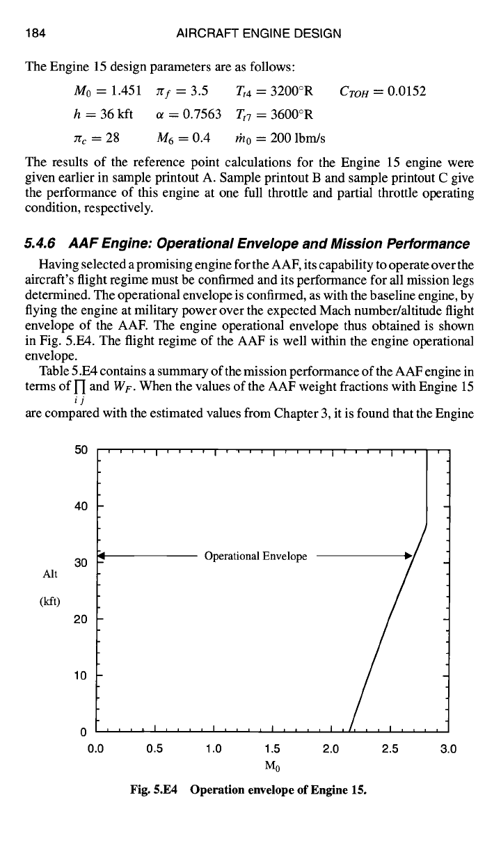
5.4.6 AAF Engine: Operational Envelope and Mission Performance
Having selected a promising engine for the AAF, its capability to operate over the
aircraft's flight regime must be confirmed and its performance for all mission legs
determined. The operational envelope is confirmed, as with the baseline engine, by
flying the engine at military power over the expected Mach number/altitude flight
envelope of the AAE The engine operational envelope thus obtained is shown
in Fig. 5.E4. The flight regime of the AAF is well within the engine operational
envelope.
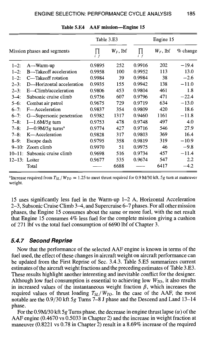
Table 5.E4 contains a summary of the mission performance of the AAF engine in
terms of ['I and WF. When the values of the AAF weight fractions with Engine 15
ij
are compared with the estimated values from Chapter 3, it is found that the Engine
Alt
(kft)
50 ' ' ' ' I ' '
40
30
20
10
0 , , , , I
0.0 0.5
' ' I ' ' ' ' I ' ' ' ' I ' ' ' ' I 'i~ ' '
-- Operational Envelope
, , I , , , i ]
I I I I ] I I
1.0 1.5 2.0 2.5 3.0
Mo
Fig. 5.E4 Operation envelope of Engine 15.
ENGINE SELECTION: PERFORMANCE CYCLE ANALYSIS
Table 5.E4 AAF
mission--Englne 15
185
Mission phases and segments
Table 3.E3 Engine 15
l-I w~, lbf H
WF,
lbf % change
if if
1-2: A Warm-up 0.9895 252 0.9916 202 -19.4
1-2: B Takeoff acceleration 0.9958 100 0.9952 113 13.0
1-2: C--Takeoff rotation 0.9984 39 0.9984 38 -2.6
2-3: D--Horizontal acceleration 0.9935 155 0.9942 138 - 11.0
2-3: E~limb/acceleration 0.9806 453 0.9804 461 1.8
3-4: Subsonic cruise climb 0.9736 607 0.9796 471 -22.4
5-6: Combat air patrol 0.9675 729 0.9719 634 -13.0
6-7: F---Acceleration 0.9837 354 0.9809 420 18.6
6-7: G--Supersonic penetration 0.9382 1317 0.9460 1161 -11.8
7-8: I--1.6M/5g turn 0.9753 478 0.9748 497 4.0
7-8: J--0.9M/5g turns a 0.9774 427 0.9716 546 27.9
7-8: K--Acceleration 0.9828 317 0.9803 369 16.4
8-9: Escape dash 0.9795 358 0.9819 319 -10.9
9-10: Zoom climb 0.9970 51 0.9975 46 -9.8
10-11: Subsonic cruise climb 0.9698 516 0.9734 457 -11.4
12-13: Loiter 0.9677 535 0.9674 547 2.2
Total 6688 6417 -4.2
aIncrease required from TSL / WTO
=
1.25 to meet thrust required for 0.9 M/30 kft, 5g turn at maneuver
weight.
15 uses significantly less fuel in the Warm-up 1-2 A, Horizontal Acceleration
2-3, Subsonic Cruise Climb 3-4, and Supercruise 6-7 phases. For all other mission
phases, the Engine 15 consumes about the same or more fuel, with the net result
that Engine 15 consumes 4% less fuel for the complete mission giving a cushion
of 271 lbf vs the total fuel consumption of 6690 lbf of Chapter 3.
5.4.7 Second Reprise
Now that the performance of the selected AAF engine is known in terms of the
fuel used, the effect of these changes in aircraft weight on aircraft performance can
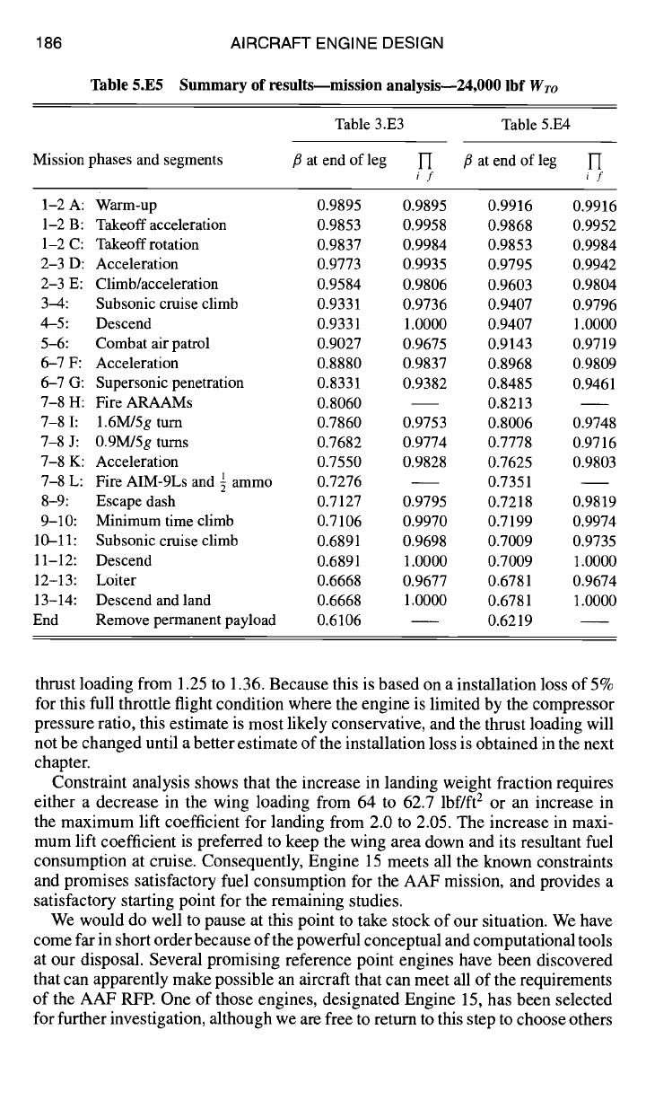
be updated from the First Reprise of Sec. 3.4.3. Table 5.E5 summarizes current
estimates of the aircraft weight fractions and the preceding estimates of Table 3.E3.
These results highlight another interesting and inevitable conflict for the designer.
Although low fuel consumption is essential to achieving low
Wro,
it also results
in increased values of the instantaneous weight fraction/3, which increases the
required values of thrust loading
TSL/Wro.
In the case of the AAF, the most
notable are the 0.9/30 kft 5g Turns 7-8 J phase and the Descend and Land 13-14
phase.
For the 0.9M/30 kft 5g Turns phase, the decrease in engine thrust lapse (or) of the
AAF engine (0.4670 vs 0.5033 in Chapter 2) and the increase in weight fraction at
maneuver (0.8221 vs 0.78 in Chapter 2) result in a 8.69% increase of the required
186
AIRCRAFT ENGINE DESIGN
Table 5.E5 Summary of resultsmmission analysis--24,000 lbf
Wro
Mission phases and segments
Table 3.E3 Table 5.E4
/3 at end of leg 1-[ /3 at end of leg l~
if if
1-2 A: Warm-up 0.9895 0.9895 0.9916 0.9916
1-2 B: Takeoff acceleration 0.9853 0.9958 0.9868 0.9952
1-2 C: Takeoff rotation 0.9837 0.9984 0.9853 0.9984
2-3 D: Acceleration 0.9773 0.9935 0.9795 0.9942
2-3 E: Climb/acceleration 0.9584 0.9806 0.9603 0.9804
3-4: Subsonic cruise climb 0.9331 0.9736 0.9407 0.9796
4-5: Descend 0.9331 1.0000 0.9407 1.0000
5-6: Combat air patrol 0.9027 0.9675 0.9143 0.9719
6--7 F: Acceleration 0.8880 0.9837 0.8968 0.9809
6-7 G: Supersonic penetration 0.8331 0.9382 0.8485 0.9461
7-8 H: Fire ARAAMs 0.8060 0.8213
7-8 I: 1.6M/5g turn 0.7860 0.9753 0.8006 0.9748
7-8 J: 0.9M/5g turns 0.7682 0.9774 0.7778 0.9716
7-8 K: Acceleration 0.7550 0.9828 0.7625 0.9803
7-8 L: Fire AIM-9Ls and ½ ammo 0.7276 0.7351
8-9: Escape dash 0.7127 0.9795 0.7218 0.9819
9-10: Minimum time climb 0.7106 0.9970 0.7199 0.9974
10-11: Subsonic cruise climb 0.6891 0.9698 0.7009 0.9735
11-12: Descend 0.6891 1.0000 0.7009 1.0000
12-13: Loiter 0.6668 0.9677 0.6781 0.9674
13-14: Descend andland 0.6668 1.0000 0.6781 1.0000
End Remove permanent payload 0.6106 0.6219
thrust loading from 1.25 to 1.36. Because this is based on a installation loss of 5%
for this full throttle flight condition where the engine is limited by the compressor
pressure ratio, this estimate is most likely conservative, and the thrust loading will
not be changed until a better estimate of the installation loss is obtained in the next
chapter.
Constraint analysis shows that the increase in landing weight fraction requires
either a decrease in the wing loading from 64 to 62.7 lbf/ft 2 or an increase in
the maximum lift coefficient for landing from 2.0 to 2.05. The increase in maxi-
mum lift coefficient is preferred to keep the wing area down and its resultant fuel
consumption at cruise. Consequently, Engine 15 meets all the known constraints
and promises satisfactory fuel consumption for the AAF mission, and provides a
satisfactory starting point for the remaining studies.
We would do well to pause at this point to take stock of our situation. We have
come far in short order because of the powerful conceptual and computational tools
at our disposal. Several promising reference point engines have been discovered
that can apparently make possible an aircraft that can meet all of the requirements
of the AAF RFP. One of those engines, designated Engine 15, has been selected
for further investigation, although we are free to return to this step to choose others

ENGINE SELECTION: PERFORMANCE CYCLE ANALYSIS 187
if the studies ahead make reconsideration desirable or necessary. The remaining
task is to develop tools that characterize the installation losses more realistically,
accounting in particular for the effects of flight conditions and throttle position.
Once these are in hand, we can fly our aircraft over the entire AAF flight envelope
in general, and the AAF mission in particular.
References
1Oates, G. C.,
The Aerothermodynamics of Gas Turbine and Rocket Propulsion,
3rd ed.,
AIAA Education Series, AIAA, Reston, VA, 1997.
2Mattingly, J. D.,
Elements of Gas Turbine Propulsion,
McGraw-Hill, New York, 1996.
3Nikkanen, J. P., and Brooky, J. D., "Single Stage Evaluation of Highly Loaded High
Mach Number Compressor Stages V," NASA CR 120887 (PWA-431 2).
4Oates, G. C. (ed.),
Aerothermodynamics of Aircraft Engine Components,
AIAA Educa-
tion Series, AIAA, New York, 1985.
5Hill, P. G., and Peterson, C. R.,
Mechanics and Thermodynamics of Propulsion,
2nd ed.,
Addison Wesley Longman, Reading, MA, 1992.
6Kerrebrock, J. L.,
Aircraft Engines and Gas Turbines,
2nd ed., Massachusetts Inst. of
Technology Press, Cambridge, MA, 1992.
7Bathie, W. W.,
Fundamentals of Gas Turbines,
2nd ed., Wiley, New York, 1995.
8 Gordon, S., and McBride, B., "Computer Program for Calculation of Complex Chemical
Equilibrium Compositions," NASA SP-273, 1971.
6
Sizing the Engine: Installed Performance
6.1 Concept
At some point in the design process, the absolute size of the engine, in terms
of some reference thrust or airflow, must be determined. Until now, a careful
distinction has been made between the installed thrust (T) required by the aircraft
and the uninstalled thrust (F) that would be produced by the isolated engine. The
difference between T and F is neither academic nor insignificant.
The uninstalled thrust represents only the ideal performance of the engine, in the
sense that it corresponds to an installation without external drag (see Appendix E).
Unfortunately, placing the engine within an airframe inevitably induces forces on
the external surfaces that increase the total drag. One might call the additional
forces the "self-drag" of the engine, but, whatever their name, they must also
be overcome by the available thrust of the engine. The uninstalled thrust must
therefore be the sum of the installed thrust and the self-drag; the latter must be
accounted for before the size, or uninstalled thrust, can be known.
This reasoning is quite logical and correct, but its practical application is not
trivial. Because the presence of the engine and its inlet, nozzle, and exhaust stream
actually influence the flow and pressure distribution over the entire aircraft, where
does the propulsion "system" begin and end? Defining the physical boundaries of
the propulsion system has been one of the greatest challenges of the aeronautics
industry, and enormous amounts of time and energy have been invested in locating
the proper "interface" between the airframe and the propulsion system.
It was not always thus. In the early days of jet-propelled aircraft, when only
relatively small turbojet engines (high F/mo) were available, the unfavorable in-
teractions between the engine and airframe were not significant. During that period
of time, it was conventional to confine the engine to its "flange-to-flange" domain,
which meant from the bolt circle at the compressor entry to the bolt circle at the
nozzle entry. When the turbofan arrived in the mid-1960s, with its larger diameter
(lower F/tho) and more sensitive and complex compression systems, installation
effects could no longer be ignored. An exciting and painful period of adjustment
then took place wherein the narrow engine boundaries were expanded in order to
improve the integrated performance of the aircraft and engine, as well as to give
engine manufacturers more control over the internal performance and operability
of their products. A clear example of this trend is evident in the case of the nacelle
mounted, high bypass ratio engines introduced around 1970 in order to dramati-
cally reduce fuel consumption. On the one hand, internal performance calculations
favor much higher bypass ratios, but the larger diameters and resulting installation
penalties prevent the benefits from being fully realized. On the other, transport
engine manufacturers have moved far from their flange-to-flange world and now
supply the entire nacelle/engine package in order to achieve the best-integrated or
installed performance.
189
190 AIRCRAFT ENGINE DESIGN
For such high performance aircraft as the Air-to-Air Fighter (AAF) of this
textbook, the engine is likely to be "buried" within the fuselage, and the division
of territorial jurisdiction becomes difficult. The engine designer would like to have
control over those external surfaces that directly interact with the engine, but cannot
possibly be responsible for the entire envelope that surrounds the engine. In the
end, the engine designer will be allowed to influence those parts that are believed
to generate the bulk of the installation penalties and are affected by the inlet
and exhaust flows. This will generally include the inlet and the nozzle, the exact
boundaries being decided by negotiation in each case. As you will see, the external
drag on the inlet and nozzle is strongly affected by the throttle setting, and it is
therefore referred to as "throttle dependent drag."
The foregoing should persuade you that engine integration has itself become a
major technology in modern aircraft design and development. Aircraft and engine
companies alike have invested heavily in this area and now have expert orga-
nizations available to deal with its problems; the government and industry have
acted collectively to produce clarifying standards. ~ Today it is known that engine
integration can have beneficial and satisfying results when considered from the
outset and done properly. When done poorly (or not at all), development crises
are invited that, in the past, have led to dramatic examples of reduced aircraft per-
formance and engine operability, increased program time and cost, and/or bitter
recriminations.
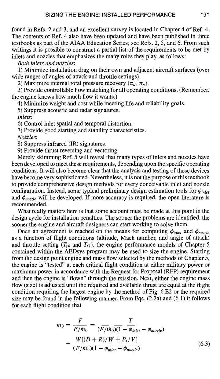
The purpose of this chapter is to provide some preliminary tools for estimating
the installation penalties that must be compensated for by added uninstalled thrust.
Only inlet and nozzle external losses will be considered, and they will be expressed
in their most convenient form, namely as a fraction of the uninstalled thrust, so that
T = F
- ~inletF - q)nozzle F
or
where
and
T
F = > T (6.1)
1 - qSi.le, - (anozzte
(Pinlet = Dintet/ F
(6.2a)
#Pnozzle = Dnozzle / F
(6.2b)
Please note that
~)inlet
and
4~nozzle
will vary with flight condition and throttle setting
for any given engine.
In addition to entering a territory rich in history and jurisprudence, this is the first
encounter in this textbook with individual engine components: inlets and nozzles.
In later chapters, the focus will be on their internal behavior in order to ensure that
they will deliver the performance assumed in the cycle calculations, but now only
their external behavior will be considered. Despite their outward appearance of
simplicity, inlets and nozzles are actually very complex devices because they must
meet many simultaneous requirements and they can have a very detrimental effect
on system performance if they do not function properly. Much good technical
work on engine/aircraft integration has been accomplished and reported over
the past 30 years, so that many references are now available. The basics can be
SIZING THE ENGINE: INSTALLED PERFORMANCE 191
found in Refs. 2 and 3, and an excellent survey is located in Chapter 4 of Ref. 4.
The contents of Ref. 4 also have been updated and have been published in three
textbooks as part of the AIAA Education Series; see Refs. 2, 5, and 6. From such
writings it is possible to construct a partial list of the requirements to be met by
inlets and nozzles that emphasizes the many roles they play, as follows:
Both inlets and nozzles:
1) Minimize installation drag on their own and adjacent aircraft surfaces (over
wide ranges of angles of attack and throttle settings).
2) Maximize internal total pressure recovery (Jra, Zrn).
3) Provide controllable flow matching for all operating conditions. (Remember,
the engine knows how much flow it wants.)
4) Minimize weight and cost while meeting life and reliability goals.
5) Suppress acoustic and radar signatures.
Inlets:
6) Control inlet spatial and temporal distortion.
7) Provide good starting and stability characteristics.
Nozzles:
8) Suppress infrared (IR) signatures.
9) Provide thrust reversing and vectoring.
Merely skimming Ref. 5 will reveal that many types of inlets and nozzles have
been developed to meet these requirements, depending upon the specific operating
conditions. It will also become clear that the analysis and testing of these devices
have become very sophisticated. Nevertheless, it is not the purpose of this textbook
to provide comprehensive design methods for every conceivable inlet and nozzle
configuration. Instead, some typical preliminary design estimation tools for
~inlet
and q~nozJe will be developed. If more accuracy is required, the open literature is
recommended.
What really matters here is that some account must be made at this point in the
design cycle for installation penalties. The sooner the problems are identified, the
sooner the engine and aircraft designers can start working to solve them.
Once an agreement is reached on the means for computing
q)inlet
and Cbnozzle
as a function of flight conditions (altitude, Mach number, and angle of attack)
and throttle setting
(Tt4
and Tt7), the engine performance models of Chapter 5
contained within the AEDsys program may be used to size the engine. Starting
from the design point engine and mass flow selected by the methods of Chapter 5,
the engine is "tested" at each critical flight condition at either military power or
maximum power in accordance with the Request for Proposal (RFP) requirement
and then the engine is "flown" through the mission. Next, either the engine mass
flow (size) is adjusted until the required and available thrust are equal at the flight
condition requiring the largest engine by the method of Fig. 6.E2 or the required
size may be found in the following manner. From Eqs. (2.2a) and (6.1) it follows
for each flight condition that
F T
rh 0 _ m
F/r'no
(F/m0)(1 -
4~in~e, - q~,ozz~e)
W[(D + R)/W + Ps/V]
(F//~/0)(1 --
q~inlet -- ~9nozzle)
(6.3)
192 AIRCRAFT ENGINE DESIGN
To find which of the flight conditions is most "demanding" (that is, requires the
largest engine), each rn0 is merely multiplied by the relevant,
(lJlOreq/rnOavail)
eval-
uated at sea level static as obtained from the performance computations. The
procedure for determining these quantities will be described in detail in Sec. 6.4.3.
You will be pleased to discover that this sizing process has been automated in
AEDsys via the Thrust Scale Factor. The largest resulting product corresponds to
what would be the largest design point engine and, therefore, the required size.
This engine will, naturally, be too large for all except the most demanding flight
condition, and actual performance at the others must be obtained later by throttling
down
Tt4
and/or
Tt7
until
F = W + -~- (1
--
(Pinlet -- q~nozzle)
(6.4)
for an engine of the chosen size. Not until this is done will the true behavior of the
engine, and especially its fuel consumption, be known.
6.2 Design Tools
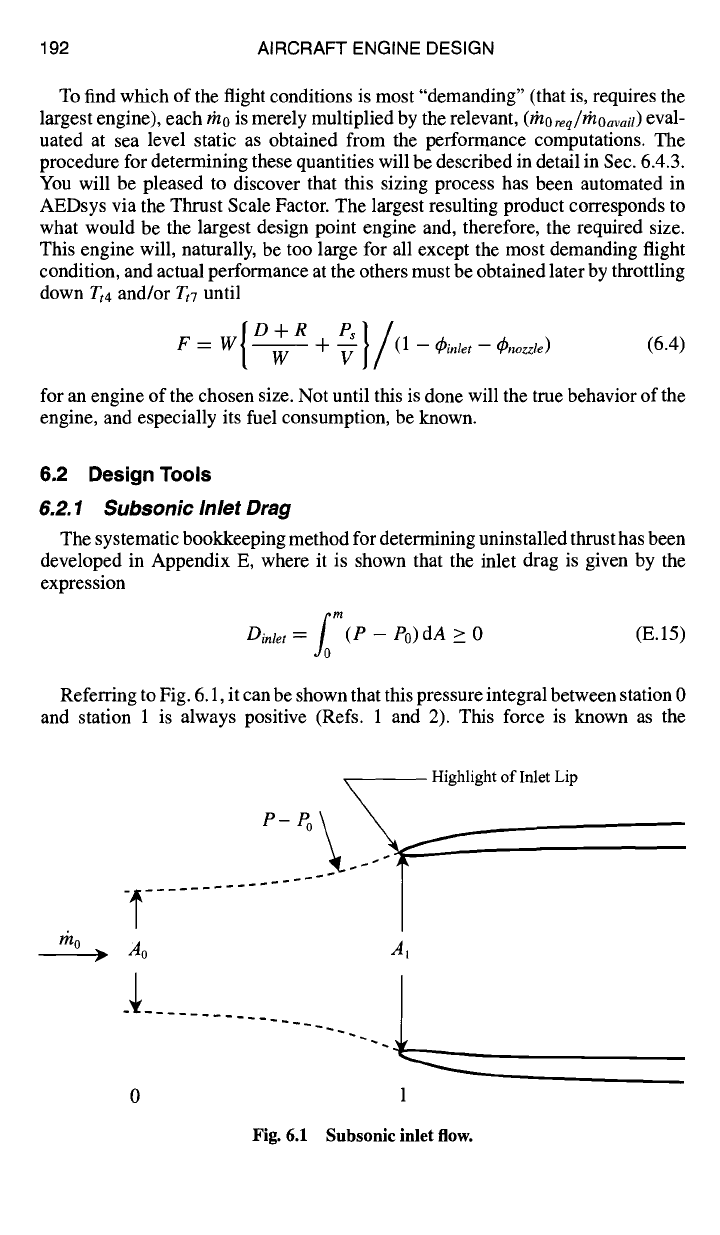
6.2.1 Subsonic Inlet Drag
The systematic bookkeeping method for determining uninstalled thrust has been
developed in Appendix E, where it is shown that the inlet drag is given by the
expression
fo m
Dinlet :-
(P -
P0)dA > 0 (E.15)
Referring to Fig. 6.1, it can be shown that this pressure integral between station 0
and station 1 is always positive (Refs. 1 and 2). This force is known as the
rho
Highlight of Inlet Lip
Ao Ai
U
0 1
Fig. 6.1 Subsonic inlet flow.