Mattingly J.D., Heiser W.H., Pratt D.T. Aircraft Engine Design
Подождите немного. Документ загружается.


SIZING THE ENGINE: INSTALLED PERFORMANCE 213
air intake
area
Alaux
equal to the inlet area A1 is selected for the AAF for M0 up
to 0.3. (See data used in revised engine search of Table 6.El.)
5) Determine the required thrust loading
(TsL/WT"o)req
for the revised mission
and constraint performance with this improved installation loss model. This was
done for the 20 engines under consideration and summarized in Table 6.El under
required thrust loading.
6) Change the available thrust loading
(TsL/WTO)avail
in the Mission Analysis
window of AEDsys to a value slightly larger than the required value
(TsL/WT"o)req
in order to resize the engine and have the program automatically scale the inlet
and afterbody data.
7) Based on the Thrust Scale Factor
(TSF),
resize engine mass flow rate (rh0)
in the parametric program for the engine design. Check that the engine(s) produce
the required power
(ProL
and/or
P'roH ).
If not, adjust the respective design values
of power takeoff coefficient
(CT-oL
and/or
Cron).
Generate a new reference engine
data file (*.ref) and input it into the AEDsys program. Check that the
TSF
is one
and that the engine(s) meet the required performance.
8) As required, repeat steps 6 and 7 until satisfactory convergence is obtained.
6.4.4 Selecting the Number of Engines
The choice of a one- or two-engine installation for the AAF is a design study
all its own and involves many tradeoffs between safety, performance, and cost.
The airframe design team is normally responsible for these studies in cooperation
with the propulsion design group. For engine designers, the purpose here is only
to verify that the engine size for either a single-or a twin-engine fighter is feasible
from the point of view of engine manufacturing and testing capabilities.
As was seen in Table 6.E2, the subsonic 5g tum sizes the Engine 15 with a
required thrust loading of 1.31 based on inlet and nozzle losses for one engine.
We therefore proceed with an available thrust loading
(TsL/WTO)avail
of 1.32 for
the AAF in order to provide some safety margin. With an available thrust loading
(TsL/WTO)avail
of 1.32, the
TSF
for one engine is 1.0323. The engine size for a
one- or two-engine installation can now be established and the feasibility of each
determined. Assuming the approximate installation losses included in Table 6.E2,
an engine design mass flow rate of either 200 x 1.0323 = 206.5 lbm/s for a single-
engine airplane or 103.3 lbm/s for a two-engine airplane is required. The sea level
static performance of each of these engines is shown in Table 6.E3.
Table 6.E3 Sea level static performance of four engines
Sea level static performance
Engine design mass
Type of aircraft flow rate, lbm/s a th0, lbm/s F, lbf
One engine 206.5 284.8 31,680
Two engine 103.3 142.4 15,840
F100-PW-229 engine b 248 29,000
F404-GE-400 engine b 142 16,000
a 1.451 M/36 kft.
bAppendix C.
214 AIRCRAFT ENGINE DESIGN
The engine size for the one-engine installation has a static sea level mass flow rate
that is about 15% higher than the F100-PW-229 engine (used in both the Air Force
F-15 and F-16) and a considerably higher maximum thrust, whereas the engine for
the two-engine installation has about the same mass flow rate as the F404-GE-400
engine (used in the U.S. Navy F- 18) and a slightly lower maximum thrust. The size
of each engine is therefore within current manufacturing and testing capabilities for
afterburning turbofan engines and either a single- or twin-engine AAF is feasible.
We have chosen a twin-engine installation for the AAF to provide you with the
experience of using this information in the computations. Thus, the Air-to-Air
Fighter for the RFP of Chapter 1 is configured to be a
two-enginefighter.
With the number of engines for the AAF now specified as two, the final sizing
of Engine 15 starts with an available system thrust loading
(TsL/WTo)av,~il
of 1.32
and the Chapter 6 installation loss. The resultant
TSF
is 0.5161. This corresponds
to an engine having sea level static thrust of 15,840 lb and a design mass flow rate
of 103.3 lbm/s.
6.4.5 Final Engine Sizing of Engine 15 for ( TsL/ WTO)avail --
1.32
AAF Engine 15 will be sized using these procedures by finding the values
of the required-to-available thrust loading
{(TsL/Wro)req/(Tsj Wro)avait}
at the
critical mission points. To determine this ratio, preliminary estimates of the inlet
and exhaust nozzle design parameters must first be established. Then, the instal-
lation losses are found using the design tools of Sec. 6.2. Next,
(TsL/Wro)req/
(TsL/WTO)avail
is determined following the procedure diagrammed in Fig. 6.E2.
Unless
(TsL/WTO)req/(ZsL/WTO)avail
'~
1.0, the engine is resized as indicated in
Fig. 6.E2.
The following series of calculations is presented here to show the methods and
procedures implemented in the AEDsys software. You may either carry out the
hand calculations for the installation loss as follows or use the AEDsys software
to do these calculations.
Inlet and exhaust nozzle design parameters--( TsL/ WTO)avail
=
1.32
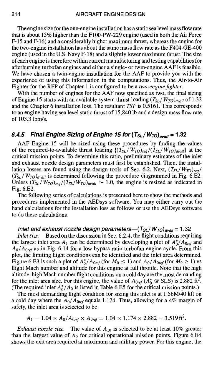
Inlet size.
Based on the discussion in Sec. 6.2.4, the flight conditions requiring
the largest inlet area A1 can be determined by developing a plot of
A~/Aoref
and
Ao/Aoref
as in Fig. 6.14 for a low bypass ratio turbofan engine cycle. From this
plot, the limiting flight conditions can be identified and the inlet area determined.
Figure 6.E3 is such a plot of
A~/Aoref
(for M0 < 1) and
Ao/Aoref
(for M0 _> 1) vs
flight Mach number and altitude for this engine at full throttle. Note that the high
altitude, high Mach number flight conditions on a cold day are the most demanding
for the inlet area size. For this engine, the value of
Aoref
(A~ @ SLS) is 2.882 fte.
(The required inlet
A~/Ao
is listed in Table 6.E5 for the critical mission points.)
The most demanding flight condition for sizing this inlet is at 1.56M/40 kft on
a cold day where the
Ao/Aoref
equals 1.174. Thus, allowing for a 4% margin of
safety, the inlet area is selected to be
A1 = 1.04 x
Ao/Aoref× Aoref=
1.04 x 1.174 × 2.882 = 3.519ft e.
Exhaust nozzle size.
The value of A10 is selected to be at least 10% greater
than the largest value of A9 for critical operational mission points. Figure 6.E4
shows the exit area required at maximum and military power. For this engine, the
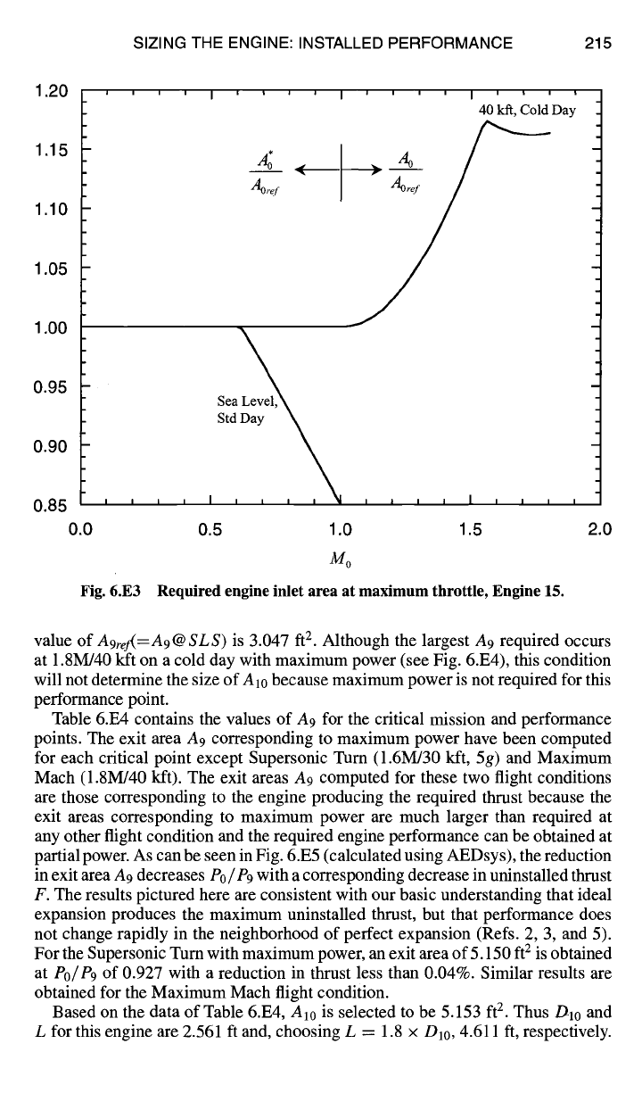
SIZING THE ENGINE: INSTALLED PERFORMANCE 215
1.20 , ,
1.15
1.10
1.05 -
1.00
0.95
0.90
0.85 ' '
0.0
Fig. 6.E3
' ' I ' ' ' '
,4£ <
A~r~
i i i i I i i i i
40 kft, Cold Day
StdDay~,
I i
i
I i I i ~1 i ! i I
i
i I i I
0.5 1.0 1.5
Mo
Required engine inlet area at maximum throttle, Engine 15.
2.0
value of
A9ref(=A9@SLS)
is 3.047 ft 2. Although the largest A9 required occurs
at 1.8M/40 kft on a cold day with maximum power (see Fig. 6.E4), this condition
will not determine the size of A10 because maximum power is not required for this
performance point.
Table 6.E4 contains the values of A9 for the critical mission and performance
points. The exit area A9 corresponding to maximum power have been computed
for each critical point except Supersonic Turn (1.6M/30 kft, 5g) and Maximum
Mach (1.8M/40 kft). The exit areas A9 computed for these two flight conditions
are those corresponding to the engine producing the required thrust because the
exit areas corresponding to maximum power are much larger than required at
any other flight condition and the required engine performance can be obtained at
partial power. As can be seen in Fig. 6.E5 (calculated using AEDsys), the reduction
in exit area A9 decreases
Po/P9
with a corresponding decrease in uninstalled thrust
F. The results pictured here are consistent with our basic understanding that ideal
expansion produces the maximum uninstalled thrust, but that performance does
not change rapidly in the neighborhood of perfect expansion (Refs. 2, 3, and 5).
For the Supersonic Turn with maximum power, an exit area of 5.150 ft 2 is obtained
at
Po/P9
of 0.927 with a reduction in thrust less than 0.04%. Similar results are
obtained for the Maximum Mach flight condition.
Based on the data of Table 6.E4, Al0 is selected to be 5.153 ft 2. Thus D10 and
L for this engine are 2.561 ft and, choosing L = 1.8 × D10, 4.611 ft, respectively.
216 AIRCRAFT ENGINE DESIGN
2.5 ',''1
I''''1''''
]t 9
A9ref
2.0
1.5
1.0
0.5
0.0
d Day "
Sea Level, Standard Day J
~ Afterburner Off
, , , , I , , , , I , , , , [ , , , ,
0.5 1.0 1.5 2.0
Mo
Fig. 6.E4 Required engine exit area at maximum throttle, Engine 15.
Table 6.E4 Engine 15 exhaust nozzle
A 9
and
IMS
for
(TsL/WTO)avail
--
1.32
Performance
M0/Alt,
requirement kft
Treq,
lbf a
Fr~q,
lbf b
% Favai!
A9, ft 2
IMS ~
Takeoff (100°F) 0.1/2 23,940 Max
Supercruise 1.5/30 10,700 5,640
Supersonic 5g turn 1.6/30 18,470 9,510
Subsonic 5g turn 0.9/30 15,220 7,740
Acceleration 1.2/30 16,780 8,470
Maximum Mach 1.8/40 9,740 4,970
7-8K Part 3 of 1.465/30 Max Max
mission accel
100.0 2.930 d 0.0604
43.24 3.065 0.0479
70.00 4.203 0.0054
99.38 4.003 d
79.33 4.608 d
46.80 3.854 0.0230
100.0 5.153 d 0.0000
aFrom Table 6.E2 for single engine.
bWwo
engines (installation loss based on single-engine results in Table 6.E2).
~A10 = 5.153 ft 2.
dMaximum throttle.
SIZING THE ENGINE: INSTALLED PERFORMANCE 217
1.005
1.002
S/S f
1.000
0.997
0.995
0.8
.... I''''1''''1''''1'~
F F
0.9 1.0 1.1 1.2 1.3
6.5
6.0
A 9
5.5
(N)
5.0
4.5
Po/P9
ref -
values at
Po/P9 = 1.0
Fig. 6.E5 Effect of exit
area
(A9) on Engine 15 performance (supersonic turn).
With these approximate nozzle design parameters determined, the integral mean
slope
(IMS)
of the nozzle can be found by using
IMS
= {1 -
(D9/Dlo)} 2
= {1 - ~}2
which follows from Eq. (6.15) with L = 1.8 x Din. The values of the exhaust
nozzle
IMS are
also given in Table 6.E6 for legs with Me > 1.2 and Me < 0.8.
Installation losses--( TsL /WTO ) avail
-- 1.32
Inlet loss coefficient.
The inlet loss coefficients are given in Sec. 6.2 as follows:
Subsonic flight:
[Mo~. (al)]/
q~i,,l~t = ~ (1 + yM~) - ~oo + yM2° [(Fg¢/rho)(yMo/ao)]
(6.6)
Supersonic flight:
~binlet= /ml - l"~lM°- /-~-~
~00 )/ ~ y- 1 2 1/2 .
2 +~_~__~M0)
}/[Fgc/(moao)]
(6.8)
218 AIRCRAFT ENGINE DESIGN
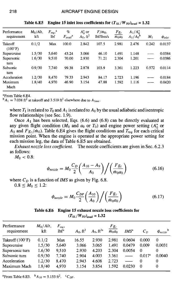
Table 6.E5 Engine 15 inlet loss coefficients for
(TsL/WTO)avail
= 1.32
Performance Mo/Alt,
Freq, a
% A~
or
F/rn o, Fgc A1/A~
requirement
kft lbf
Favail a
Ao, ft 2 lbf/lbm/s
rhoao A l/Ao b M1
q~inlet
Takeoff 0.1/2 Max 100.0 2.842 107.5 2.981 2.476
(100°F)
Supercruise
1.5/30 5,640 43.24 3.066 46.10 1.491 1.148
Supersonic
1.6/30 9,510 70.00 2.930 71.21 2.304 1.201
turn
Subsonic
0.9/30 7,740 99.38 2.878 103.9 3.361 1.223
turn
Acceleration
1.2/30 8,470 79.33 2.943 84.17 2.723 1.196
Maximum 1.8/40 4,970 46.90 3.154 47.88 1.592 1.116
Mach
0.242
0.572
0.0137
0.0384
0.0386
0.0114
0.0184
0.0420
aFrom Table 6.E4.
bA 1 = 7.038 ft 2 at takeoff and 3.519 ft 2
elsewhere due to
Ala,x.
where TI is related to To and A1 is related to A0 by the usual adiabatic and isentropic
flow relationships (see Sec. 1.9).
Once A1 has been selected, Eqs. (6.6) and (6.8) can be directly evaluated at
any given flight condition (M0 and ao or To) and engine power setting (A; or
A0 and
Fgc/rho).
Table 6.E4 gives the flight conditions and
Tre q
for each critical
mission point. When the engine is operated at the appropriate power setting for
each mission leg, the data of Table 6.E5 are obtained.
Exhaust nozzle loss coefficient.
The nozzle coefficients are given in Sec. 6.2.3
as follows:
Mo < 0.8:
CD(Alo-A9)/(Fgc~
(6.16)
~)nozzle = MO ~'- \ -Ao \ rhoao /
where
CD
is
a function
oflMS
as given
by Fig. 6.8.
0.8 < M0 < 1.2:
~nozzle
m°2
\ Ao ] / \ moao /
(6.17)
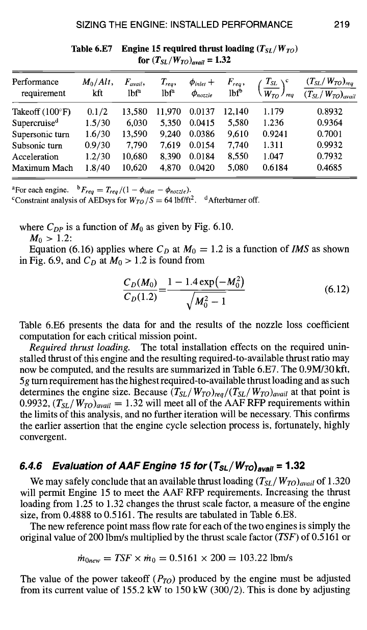
Table 6.E6 Engine 15 exhaust nozzle loss coefficients for
(rsL/Wro)avai I =
1.32
Performance Mo/Alt, Freq, Fgc
requirement
kft lbf a A0, ft 2
A9, ft 2a
rhoa0
IMS a CD dpnozzte b
Takeoff(100°F) 0.1/2 Max 16.55 2.930 2.981 0.0604 0.000 0
Supercruise
1.5/30 5,640 3.066 3.065 1.491 0.0479 0.009 0.0031
Supersonic
turn 1.6/30 9,510 2.930 4.203 2.304 0.0054 0 0
Subsonic
turn 0.9/30 7,740 2.904 4.003 3.361 0.017 c 0.0040
Acceleration
1.2/30 8,470 2.943 4.608 2.723 0 0
MaximumMach 1.8/40 4,970 3.154 3.854 1.592 0.0230 0 0
aFrom Table 6.E3. hA10 = 5.153 ft 2.
cCDp.
SIZING THE ENGINE: INSTALLED PERFORMANCE
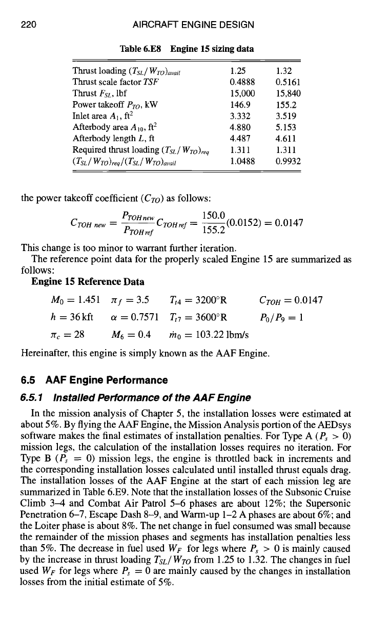
Table 6.E7 Engine 15 required thrust loading
(TsL/Wro)
for
(TsL/Wro)avail
= 1.32
219
Performance
Mo/ Alt, Favail, Treq, ~inlet "~ Freq, ( Ts L ~c (ZsL / WTO)re q
requirement kft lbP lbP
(~nozzle
lbfb
\-~OTO]req
(TsL/WTO)avail
Takeoff(100°F) 0.1/2 13,580 11,970 0.0137 12,140 1.179 0.8932
Supercruise a 1.5/30 6,030 5,350 0.0415 5,580 1.236 0.9364
Supersonic turn 1.6/30 13,590 9,240 0.0386 9,610 0.9241 0.7001
Subsonic turn 0.9/30 7,790 7,619 0.0154 7,740 1.311 0.9932
Acceleration 1.2/30 10,680 8,390 0.0184 8,550 1.047 0.7932
Maximum Mach 1.8/40 10,620 4,870 0.0420 5,080 0.6184 0.4685
aFor each engine,
b Freq = Treq /(1 - ~in!et - ~nozzle).
CConstraint analysis of AEDsys for
WT-o/S
= 64 lbf/ft 2. dAfterbumer off.
where Cop is a function of M0 as given by Fig. 6.10.
M0 > 1.2:
Equation (6.16) applies where CD at M0 = 1.2 is a function oflMS as shown
in Fig. 6.9, and Co at M0 > 1.2 is found from
Co(Mo) 1- 1.4exp(-M 2)
= r--- (6.12)
Co(1.2)
./M 2 - 1
Table 6.E6 presents the data for and the results of the nozzle loss coefficient
computation for each critical mission point.
Required thrust loading. The total installation effects on the required unin-
stalled thrust of this engine and the resulting required-to-available thrust ratio may
now be computed, and the results are summarized in Table 6.E7. The 0.9M/30 kft,
5g turn requirement has the highest required-to-available thrust loading and as such
determines the engine size. Because (TsL/WTO)req/(TsL/WTO)avail at that point is
0.9932, (Tsr/WTO)avail
"~-
1.32 will meet all of the AAF RFP requirements within
the limits of this analysis, and no further iteration will be necessary. This confirms
the earlier assertion that the engine cycle selection process is, fortunately, highly
convergent.
6.4.6 Evaluation of AAF Engine 15 for
( TsL / WTO)avail
-
1.32
We may safely conclude that an available thrust loading (TsL/WTO)avail of 1.320
will permit Engine 15 to meet the AAF RFP requirements. Increasing the thrust
loading from 1.25 to 1.32 changes the thrust scale factor, a measure of the engine
size, from 0.4888 to 0.5161. The results are tabulated in Table 6.E8.
The new reference point mass flow rate for each of the two engines is simply the
original value of 200 lbm/s multiplied by the thrust scale factor (TSF) of 0.5161 or
thOnew = TSF × rh0 = 0.5161 x 200 = 103.22 lbm/s
The value of the power takeoff (Pro) produced by the engine must be adjusted
from its current value of 155.2 kW to 150 kW (300/2). This is done by adjusting
220 AIRCRAFT ENGINE DESIGN
Table 6.E8 Engine 15 sizing data
Thrust loading
(TsL/WTo)avait
1.25 1.32
Thrust scale factor
TSF
0.4888 0.5161
Thrust
FsL,
lbf 15,000 15,840
Power takeoff
Pro,
kW 146.9 155.2
Inlet area A1, ft 2 3.332 3.519
Afterbody area Al0, ft 2 4.880 5.153
Afterbody length L, ft 4.487 4.611
Required thrust loading
(TsL/WTo)req
1.311 1.311
(TsL/WTO)req/(TsL/WTO)avail
1.0488 0.9932
the power takeoff coefficient
(Cro)
as follows:
PTOHnew
150.0
Cron new -- ProHref CT"oHref
= 1-~.2(0.0152). =
0.0147
This change is too minor to warrant further iteration.
The reference point data for the properly scaled Engine 15 are summarized as
follows:
Engine 15 Reference Data
M0 = 1.451 7/f = 3.5
Tt4
= 3200°R
Crow
= 0.0147
h = 36kft a = 0.7571 Tt7 = 3600°R
Po/P9 = 1
Zrc = 28 M6 = 0.4 rh0 = 103.22 lbm/s
Hereinafter, this engine is simply known as the AAF Engine.
6.5 AAF Engine Performance
6.5.1 Installed Performance of the AAF Engine
In the mission analysis of Chapter 5, the installation losses were estimated at
about 5%. By flying the AAF Engine, the Mission Analysis portion of the AEDsys
software makes the final estimates of installation penalties. For Type A (Ps > 0)
mission legs, the calculation of the installation losses requires no iteration. For
Type B (Ps = 0) mission legs, the engine is throttled back in increments and
the corresponding installation losses calculated until installed thrust equals drag.
The installation losses of the AAF Engine at the start of each mission leg are
summarized in Table 6.E9. Note that the installation losses of the Subsonic Cruise
Climb 3-4 and Combat Air Patrol 5-6 phases are about 12%; the Supersonic
Penetration 6-7, Escape Dash 8-9, and Warm-up 1-2 A phases are about 6%; and
the Loiter phase is about 8%. The net change in fuel consumed was small because
the remainder of the mission phases and segments has installation penalties less
than 5%. The decrease in fuel used WF for legs where Ps > 0 is mainly caused
by the increase in thrust loading
Tsj Wro
from 1.25 to 1.32. The changes in fuel
used
WF
for legs where Ps = 0 are mainly caused by the changes in installation
losses from the initial estimate of 5%.
SIZING THE ENGINE: INSTALLED PERFORMANCE
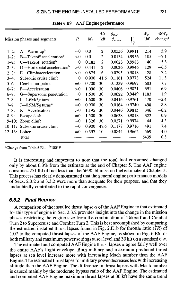
Table 6.E9 AAF Engine performance
221
Mission phases and segments Ps
Alt, (])inlet "~- WF, o~OWF
114o kft
(/)nozzle 1-I
lbf change a
if
1-2: A--Warm-up b =0 0.0 2 0.0556 0.9911 214 5.9
1-2: B--Takeoffacceleration b >0 0.0 2 0.0134 0.9956 105 -7.1
1-2: C--Takeoffrotation b =0 0.182 2 0.0023 0.9983 40 5.3
2-3: D--Horizontal acceleration b >0 0.441 2 0.0026 0.9946 129 -6.5
2-3: E--Climb/acceleration >0 0.875 16 0.0295 0.9818 428 -7.2
3--4: Subsonic cruise climb -----0 0.900 41.6 0.1161 0.9773 524 11.3
5-6: Combat air patrol =0 0.700 30 0.1239 0.9697 683 7.7
6-7: F--Acceleration >0 1.090 30 0.0408 0.9821 391 -6.9
6-7: G--Supersonic penetration =0 1.500 30 0.0622 0.9449 1183 1.9
7-8: I--1.6M/5gtum =0 1.600 30 0.0416 0.9761 470 -5.4
7-8: J--0.9M/5gtums* =0 0.900 30 0.0164 0.9740 498 -8.8
7-8: K--Acceleration >0 1.195 30 0.0446 0.9815 346 -6.2
8-9: Escape dash =0 1.500 30 0.0638 0.9818 322 0.9
9-10: Zoom climb =0 1.326 30 0.0271 0.9974 44 -4.3
10-11: Subsonic cruise climb =0 0.900 47.6 0.1177 0.9716 491 7.4
12-13: Loiter =0 0.397 10 0.0844 0.9662 569 4.0
Total 6439 0.3
aChange from Table 5.E4. bl00°E
It is interesting and important to note that the total fuel consumed changed
only by about 0.3% from the estimate at the end of Chapter 5. The AAF engine
consumes 251 lbf of fuel less than the 6690 lbf mission fuel estimate of Chapter 3.
This process has clearly demonstrated that the general engine performance models
of Secs. 2.3.2 and 3.3.2 were more than adequate for their purpose, and that they
undoubtedly contributed to the rapid convergence.
6.5.2 Final Reprise
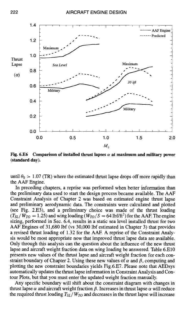
A comparison of the installed thrust lapse ot of the AAF Engine to that estimated
for this type of engine in Sec. 2.3.2 provides insight into the change in the mission
phases restricting the engine size from the combination of Takeoff and Combat
Turn 2 to Supercruise and Combat Turn 2. This is best accomplished by comparing
the estimated installed thrust lapses found in Fig. 2.Elb for throttle ratio
(TR)
of
1.07 to the computed thrust lapses of the AAF Engine, as shown in Fig. 6.E6 for
both military and maximum power settings at sea level and 30 kft on a standard day.
The estimated and computed AAF Engine thrust lapses ot agree fairly well over
the entire AAF's flight envelope. Both military and maximum predicted thrust
lapses at sea level increase more with increasing Mach number than the AAF
Engine. The estimated thrust lapse for military power decreases less with increasing
altitude than the AAF Engine. The difference in thrust lapses with Mach number
is caused mainly by the moderate bypass ratio of the AAF Engine. The estimated
and computed AAF Engine maximum thrust lapses at 30 kft have the same trend
222 AIRCRAFT ENGINE DESIGN
Thrust
Lapse
(~)
1.4
1.2
1.0
0.8
0.6
0.4
0.2
' ' ' I ' ' i i I
pl
Sea Level
Max~um
Milita~ ,~...'~
] i i p i
-- AAF Engine"
...... Predicted
0.0
~ ~ ~ , I ~ ~ , , I ~ ~ ~ L I ~ , ~ ,
0.0 0.5 1.0 1.5 2.0
Mo
Fig. 6.E6 Comparison of installed thrust lapses ~ at maximum and military power
(standard day).
until 00 > 1.07 (TR) where the estimated thrust lapse drops off more rapidly than
the AAF Engine.
In preceding chapters, a reprise was performed when better information than
the preliminary data used to start the design process became available. The AAF
Constraint Analysis of Chapter 2 was based on estimated engine thrust lapse
and preliminary aerodynamic data. The constraints were calculated and plotted
(see Fig. 2.E3), and a preliminary choice was made of the thrust loading
(TsL/Wro
= 1.25) and wing loading
(Wro/S
= 64 lbf/ft 2) for the AAE The engine
sizing, performed in Sec. 6.4, results in a static sea level installed thrust for two
AAF Engines of 31,680 lbf (vs 30,000 lbf estimated in Chapter 3) that provides
a revised thrust loading of 1.32 for the AAE A reprise of the Constraint Analy-
sis would be most appropriate now that improved thrust lapse data are available.
Only through this analysis can the question about the influence of the new thrust
lapse and aircraft weight fraction data on wing loading be answered. Table 6.El0
presents new values of the thrust lapse and aircraft weight fraction for each con-
straint boundary of Chapter 2. Using these new values of t~ and ~, computing and
plotting the new constraint boundaries yields Fig.6.E7. Please note that AEDsys
automatically updates the thrust lapse information in Constraint Analysis and Con-
tour Plots, but that you must enter the updated weight fraction manually.
Any specific boundary will shift about the constraint diagram with changes in
thrust lapse a and aircraft weight fraction ft. Increases in thrust lapse ot will reduce
the required thrust loading
Tsc/Wro
and decreases in the thrust lapse will increase