Mattingly J.D., Heiser W.H., Pratt D.T. Aircraft Engine Design
Подождите немного. Документ загружается.

DESIGN: GLOBAL AND INTERFACE QUANTITIES
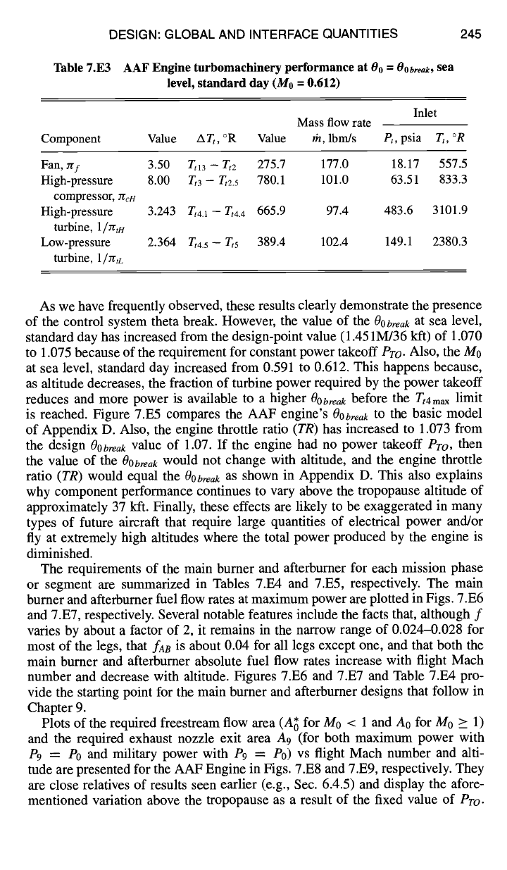
Table 7.E3 AAF Engine turbomachinery performance at
Oo
=
OObreak,
sea
level, standard day (M0 = 0.612)
245
Inlet
Mass flow rate
Component Value
ATt,
°R Value th, lbm/s
Pt,
psia Tt, °R
Fan, ygf 3.50 Tt13 - Tt2 275.7 177.0 18.17 557.5
High-pressure 8.00 T,3 - Tt2.5 780.1 101.0 63.51 833.3
compressor, JrcH
High-pressure 3.243 Tt4.1 - Tt4.4 665.9 97.4 483.6 3101.9
turbine,
1/ntI4
Low-pressure 2.364 Tt4.5 - T,5 389.4 102.4 149.1 2380.3
turbine,
1/~tL
As we have frequently observed, these results clearly demonstrate the presence
of the control system theta break. However, the value of the
OObre,,k
at sea level,
standard day has increased from the design-point value (1.451M/36 kft) of 1.070
to 1.075 because of the requirement for constant power takeoff
Pro.
Also, the M0
at sea level, standard day increased from 0.591 to 0.612. This happens because,
as altitude decreases, the fraction of turbine power required by the power takeoff
reduces and more power is available to a higher
OObreak
before the
Tt4ma x
limit
is reached. Figure 7.E5 compares the AAF engine's
Oooreak
to the basic model
of Appendix D. Also, the engine throttle ratio
(TR)
has increased to 1.073 from
the design
OObreak
value of 1.07. If the engine had no power takeoff
Pro,
then
the value of the 00
break
would not change with altitude, and the engine throttle
ratio
(TR)
would equal the
OObreak
as shown in Appendix D. This also explains
why component performance continues to vary above the tropopause altitude of
approximately 37 kft. Finally, these effects are likely to be exaggerated in many
types of future aircraft that require large quantities of electrical power and/or
fly at extremely high altitudes where the total power produced by the engine is
diminished.
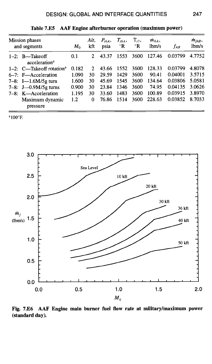
The requirements of the main burner and afterburner for each mission phase
or segment are summarized in Tables 7.E4 and 7.E5, respectively. The main
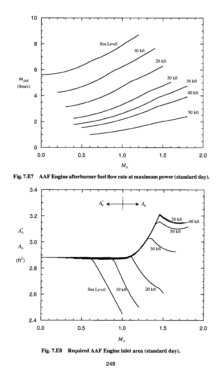
burner and afterburner fuel flow rates at maximum power are plotted in Figs. 7.E6
and 7.E7, respectively. Several notable features include the facts that, although f
varies by about a factor of 2, it remains in the narrow range of 0.024-0.028 for
most of the legs, that
faB
is about 0.04 for all legs except one, and that both the
main burner and afterburner absolute fuel flow rates increase with flight Mach
number and decrease with altitude. Figures 7.E6 and 7.E7 and Table 7.E4 pro-
vide the starting point for the main burner and afterburner designs that follow in
Chapter 9.
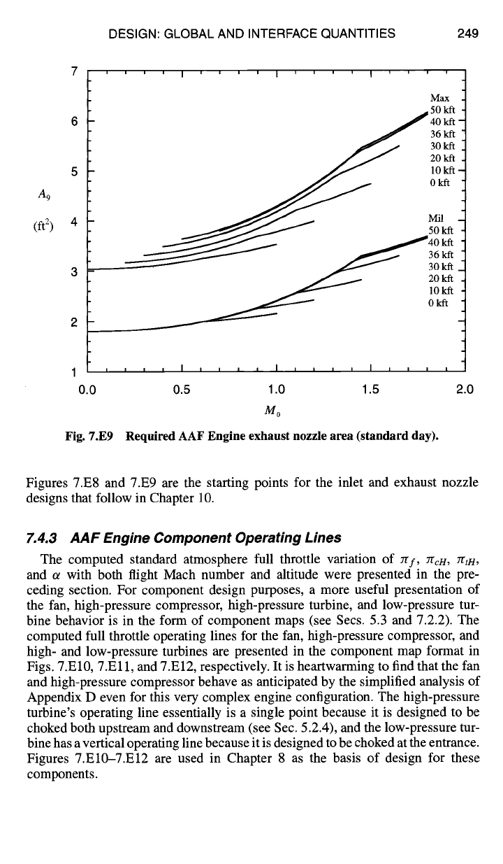
Plots of the required freestream flow area (A; for M0 < 1 and A0 for M0 _> 1)
and the required exhaust nozzle exit area A9 (for both maximum power with
P9 = P0 and military power with P9 = P0) vs flight Mach number and alti-
tude are presented for the AAF Engine in Figs. 7.E8 and 7.E9, respectively. They
are close relatives of results seen earlier (e.g., Sec. 6.4.5) and display the afore-
mentioned variation above the tropopanse as a result of the fixed value of
Pro.
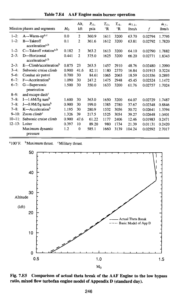
Table 7.E4 AAF Engine main burner operation
Alt, Pt3, Tt3,
Tt4,
th3.1, ~lf,
Mission phases and segments 340 kft psia °R °R lbm/s f lbm/s
1-2: A--Warm-up a,c 0.0 2
1-2: B--Takeoff 0.1 2
acceleration a,b
1-2: C--Takeoff rotation a,b 0.182 2
2-3: D Horizontal 0.441 2
acceleration a,b
2-3: E~limb/acceleration b 0.875 23
3-4: Subsonic cruise climb
5-6: Combat air patrol
6-7: F--Acceleration b
6-7: G--Supersonic
penetration
8-9: and escape dash c
7-8: I--1.6M/5g turn b
7-8: J~0.9M/5g turns b
7-8: K Acceleration b
9-10: Zoom climb c
10-11 : Subsonic cruise climb
12-13: Loiter
Maximum dynamic
pressure
360.9 1611 3200 63.70 0.02794 1.7795
361.6 1612 3200 63.81 0.02792 1.7820
363.2 1613 3200 64.10 0.02790 1.7882
375.0 1625 3200 66.20 0.02771 1.8343
263.5 1457 2910 48.76 0.02480 1.2090
0.900 41.6 82.11 1180 2370 16.84 0.01915 0.3224
0.700 30 84.61 1065 2065 18.59 0.01556 0.2893
1.090 30 247.2 1475 2948 45.45 0.02524 1.1472
1.500 30 350.0 1633 3200 61.76 0.02757 1.7024
1.600 30 363.0 1650 3200 64.07 0.02729 1.7487
0.900 30 199.0 1385 2780 37.67 0.02348 0.8846
1.195 30 280.9 1532 3056 50.72 0.02641 1.3394
1.326 39 217.5 1525 3054 39.27 0.02648 1.0401
0.900 47.6 61.22 1177 2406 12.46 0.01983 0.2471
0.397 10 89.20 980 1734 21.39 0.01131 0.2420
1.2 0 585.1 1660 3139 104.24 0.02592 2.7017
al00°E bMaximumthrust. CMilitary thrust.
fi0
40
30
Altitude
(kft)
20
10
0
0.5 1.5
i i i i i i i , , I i i i i , i i i i
f Actual Theta Break
.... Basic Model of App D
, i~1 i i , i , , I , I I I I I I I I
1.0
M0
Fig. 7.E5 Comparison of actual theta break of the AAF Engine to the low bypass
ratio, mixed flow turbofan engine model of Appendix D (standard day).
246
DESIGN: GLOBAL AND INTERFACE QUANTITIES
Table 7.E5 AAF Engine afterburner operation (maximum power)
247
Mission phases
Alt, et6A,
Tt6A, Tt7, /'f/6A,
I~lfAB,
and segments M0 kft psia °R °R lbrn/s
fa8
lbm/s
1-2: B--Takeoff 0.1 2 43.37 1553 3600 127.46 0.03799 4.7752
acceleration a
1-2: C--Takeoffrotation a 0.182 2 43.66 1552 3600 128.33 0.03799 4.8078
6-7: F--Acceleration 1.090 30 29.59 1429 3600 90.41 0.04001 3.5715
7-8: I---1.6M/5gturn 1.600 30 45.69 1545 3600 134.64 0.03806 5.0581
7-8: J--0.9M/5gturns 0.900 30 23.84 1346 3600 74.95 0.04135 3.0626
7-8: K--Acceleration 1.195 30 33.60 1483 3600 100.89 0.03915 3.8970
Maximum dynamic 1.2 0 76.86 1514 3600 228.63 0.03852 8.7033
pressure
al00°E
3.0 .... I .... I .... I
....
Sea Level~ "I'''-~
(Ibm/s) 1.5
1.0
kft
0.5
0.0
~ , , , I , , , t I , , , , I , , , ,
0.0 0.5 1.0 1.5 2.0
Mo
Fig. 7.E6 AAF Engine main burner fuel flow rate at military/maximum power
(standard day).
10 .... i .... i .... i ....
/~fAB
(lbrrds)
Sea LevelJ
30 kft 36 kft
0
0.0 0.5 1.0 1.5 2.0
Mo
Fig. 7.E7 AAF Engine afterburner fuel flow rate at maximum power (standard day).
3.4
3.2
a;
3.0
Ao
(ft 2)
2.8
2.6
, , , , I i , , , , 1 i , I , , , ,
~
40 kft
ft
II
Se~ ~ 20 kft ~
2.4 , i , ~ I i i i , , J , ~ I ~ i ~
0.0 0.5 1.0 1.5
2.0
M o
Fig. 7.E8 Required AAF Engine inlet area (standard day).
248
DESIGN: GLOBAL AND INTERFACE QUANTITIES 249
a 9
(ft 2)
' ' ' I ' ' ' ' I ' ' ' ' I ' ' ' '
Max
~
50 kft
40 kft
36 kft
30 kft
20 kft
10kft
0kft
Mil
~.~ 50 kft
~ 36kft
~,,"'~ 30 kft
J~ 20 lift
~10 kft
1 , , , , I , , , , I , , , , I , , , ,
0.0 0.5 1.0 1.5 2.0
Mo
Fig. 7.E9 Required AAF Engine exhaust nozzle area (standard day).
Figures 7.E8 and 7.E9 are the starting points for the inlet and exhaust nozzle
designs that follow in Chapter 10.
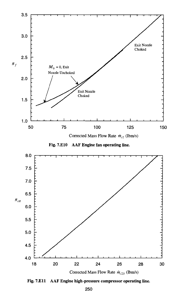
7.4.3 AAF Engine Component Operating Lines
The computed standard atmosphere full throttle variation of
7[f,
7[cH , 7[tH ,
and ot with both flight Mach number and altitude were presented in the pre-
ceding section. For component design purposes, a more useful presentation of
the fan, high-pressure compressor, high-pressure turbine, and low-pressure tur-
bine behavior is in the form of component maps (see Sees. 5.3 and 7.2.2). The
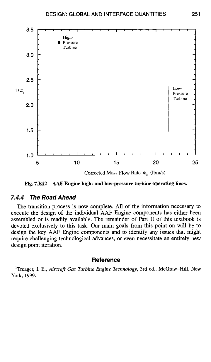
computed full throttle operating lines for the fan, high-pressure compressor, and
high- and low-pressure turbines are presented in the component map format in
Figs. 7.El0, 7.El 1, and 7.E12, respectively. It is heartwarming to find that the fan
and high-pressure compressor behave as anticipated by the simplified analysis of
Appendix D even for this very complex engine configuration. The high-pressure
turbine's operating line essentially is a single point because it is designed to be
choked both upstream and downstream (see Sec. 5.2.4), and the low-pressure tur-
bine has a vertical operating line because it is designed to be choked at the entrance.
Figures 7.E10-7.E12 are used in Chapter 8 as the basis of design for these
components.
3.5
~f
~cH
3.0
2.5
2.0
1.5
1.0 t..
5O
Exit Nozzle
Choked
M o =
0, Exit
Nozzle Unchoked
/ \
Choked
75
Fig. 7.E10
100 125
Corrected Mass Flow Rate
thc2
(Ibm/s)
AAF Engine fan operating line.
8.0
7.5
7.0
6.5
6.0
5.5
5.0
4.5
4.0
'''1'''1'''1'''1'''1''
18
Fig. 7.Ell
20 22 24 26 28
Corrected Mass Flow Rate rh,25 (Ibm/s)
AAF Engine high-pressure compressor operating line.
250
150
30
DESIGN: GLOBAL AND INTERFACE QUANTITIES 251
3.5
3.0
2.5
l/Tr t
2.0
1.5
t i i I
High-
• Pressure
Turbine
Fig. 7.E12
I''''1''
Low-
Pressure
Turbine
1,0 , , , , I , , t , I i i
....
5 10 15 20 25
Corrected Mass Flow Rate rh,. (lbm/s)
AAF Engine high- and low-pressure turbine operating lines.
7.4.4 The Road Ahead
The transition process is now complete. All of the information necessary to
execute the design of the individual AAF Engine components has either been
assembled or is readily available. The remainder of Part II of this textbook is
devoted exclusively to this task. Our main goals from this point on will be to
design the key AAF Engine components and to identify any issues that might
require challenging technological advances, or even necessitate an entirely new
design point iteration.
Reference
1Treager, I. E., Aircraft Gas Turbine Engine Technology, 3rd ed., McGraw-Hill, New
York, 1999.
8
Engine Component Design:
Rotating Turbomachinery
8.1 Concept
The general purpose of rotating machines is to exchange mechanical energy
with a flowing stream of fluid. The turbomachines found in airbreathing engines
take many forms, such as fans, compressors, turbines, free or power turbines, and
propellers. The design of these devices is one of the most critical and difficult
steps in the engine development process, for no progress with real hardware can
be made until all of the rotating components are in working order.
Although this chapter begins with the consideration of aerodynamics, durability
or life issues are equally important. Because turbomachines are expected to run for
thousands of hours without major overhaul, it follows that they cannot be based
upon aerodynamic requirements alone. A successful machine results only from
a highly iterative series of thoughtful aerodynamic, heat transfer, materials, and
structural evaluations. The best solution to each design problem effectively couples
respect for the important factors together in the correct proportions. The design
tools of this chapter will clearly illustrate the interdependency of aerodynamics
and structures. Moreover, the push and pull of the requirements of components
attached to the same shaft will also be demonstrated.
This chapter will be flirting with the most impenetrable and "proprietary" do-
mains of the engine companies because of their heavy investment in these technolo-
gies, as well as the great competitive advantages that accrue to proven superiority.
It is well to take note of the corollary, namely, that the enormous capabilities they
possess, including sophisticated computer programs, technical data, and seasoned
experience, are virtually impossible to reproduce in the classroom. Indeed, many
experts have spent their entire careers learning to deal with one or two facets of
the design problems of rotating turbomachinery.
Because there is no single, absolute answer to each question, this is also an area
where judgment and personal preferences can strongly influence the outcome. It is
therefore true that many decisions are based upon feelings that are not completely
articulated.
How can the spirit of this process be captured in a basic design course and still
make it possible to create quantitative solutions? Our hopes rest on the design
tools that express the primary physical phenomena at work. These tools are simple
enough to be rapidly applied, yet they contain enough complexity that final choices
must be based on judgment. Those who participate in this process will be impressed
with their accomplishments and awed by what must take place in the "real world."
The study of rotating machinery is not new, and many excellent books and re-
ports have been written for the benefit of students and practicing professionals
(see Refs. 1-9). Because it is impossible to reproduce even the smallest fraction
253
254 AIRCRAFT ENGINE DESIGN
of that information in one chapter, the readers are urged to use the open literature
generously in their work. Special attention is drawn to Refs. 1 and 2, which are
textbooks covering turbomachinery and many related propulsion design subjects.
They also contain excellent lists of references for those who wish to listen directly
to the masters.
To restrain the growth of this textbook, material on such nonaxial turbomachin-
ery components as centrifugal compressors, folded combustors, and radial turbines
has not been included. These devices play an important role in propulsion, partic-
ularly in small engines, and can be a part of the best design solution. References
2 and 8-11 will provide a starting point for their study.
Finally, when discussing the parts of compressors and turbines, one finds a
proliferation of terminology in the open literature. In particular, the stationary
airfoils, which are usually suspended from the outer case, are frequently referred
to as stators, vanes, or nozzles, whereas the rotating airfoils, which are usually
attached to an internal disk, are often called rotors or blades. We have attempted
to use uniform, generic terms, but great care is advised as you move through this
thicket.
8.2 Design Tools
This material outlines the development and summarizes the results for several
key building blocks used in the design of axial flow rotating machines. These
tools are consistent with those used throughout this textbook in the sense that they
correctly represent the dominant physical phenomena. The results will therefore
faithfully reproduce the main trends of the real world, as well as numbers that
are in the right ballpark, but without the excessive costs that accompany extreme
accuracy. An additional benefit of this approach is an analytical transparency that
leads to clearer understanding and sounder reasoning.
These analyses provide all of the procedures required to reach usable results.
Their development draws heavily on the material found in Ref. 11. This includes,
in particular, the compressor and turbine nomenclature and velocity diagram nota-
tion, both of which are consistent with that found in the standard turbomachinery
literature, and with the detailed axial flow compressor and turbine design programs
of AEDsys designated, respectively, as COMPR and TURBN.
8.2.1 Fan and Compressor Aerodynamics
8.2. 1. I Axial flow, constant axial velocity, repeating stage, repeating
row, mean-line design.
The primary goal of this section is to describe a method
that will allow you to rapidly create advanced fan and compressor stage designs
and automatically generate very reliable initial estimates for the truly enormous
amounts of technical data required as input for COMPR. This shortcut is the critical
ingredient that allows you to make your own design choices, while revealing the
essence of how fan and compressor stages behave. If the method strikes you as
outrageously effortless, you may find comfort in the fact that similar methods are
used as the starting point in industry.
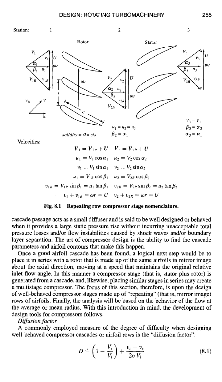
The basic building block of the aerodynamic design of axial flow compressors is
the cascade, an endlessly repeating array of airfoils (Fig. 8.1) that results from the
conceptual "unwrapping" of the stationary (stator) or rotating (rotor) airfoils. Each
DESIGN: ROTATING TURBOMACHINERY 255
Station: 1 2 3
Rotor Stator
Vl g~ lUr ~ ~~lUr
vv I
gl = /42 = N3
solidity = or= c/s
Velocities:
V1 = V~R + U
U 1 ~ V 1 COS~/1
U 1 = V 1 sinotl
ul = Vie cos~l
VlR = V1R sin/3j = Ul tan/31
1,91 -~- I)IR ~ O)F ~ U
Fig. 8.1
1~2 = Ogl
V 2 = V2R + U
1,12 ~ V2 cos ol 2
V2 = V2 sinot2
u2 = V2R cos ¢~2
v2e = V2R sin t2 = u2 tan t2
1) 2 -]- 1/2R ~ 09/" ~ U
Repeating row compressor stage nomenclature.
V3=V l
t3 = °~2
a 3 = a 1
cascade passage acts as a small diffuser and is said to be well designed or behaved
when it provides a large static pressure rise without incurring unacceptable total
pressure losses and/or flow instabilities caused by shock waves and/or boundary
layer separation. The art of compressor design is the ability to find the cascade
parameters and airfoil contours that make this happen.
Once a good airfoil cascade has been found, a logical next step would be to
place it in series with a rotor that is made up of the same airfoils in mirror image
about the axial direction, moving at a speed that maintains the original relative
inlet flow angle. In this manner a compressor stage (that is, stator plus rotor) is
generated from a cascade, and, likewise, placing similar stages in series may create
a multistage compressor. The focus of this section, therefore, is upon the design
of well-behaved compressor stages made up of "repeating" (that is, mirror image)
rows of airfoils. Finally, the analysis will be based on the behavior of the flow at
the average or mean radius. With this introduction in mind, the development of
design tools for compressors follows.
Diffusion factor
A commonly employed measure of the degree of difficulty when designing
well-behaved compressor cascades or airfoil rows is the "diffusion factor":
g/) v,-ve
D-- 1-Ve + 2o'----~/ (8.1)