Mattingly J.D., Heiser W.H., Pratt D.T. Aircraft Engine Design
Подождите немного. Документ загружается.

SIZING THE ENGINE: INSTALLED PERFORMANCE
Table 6.El0 AAF thrust lapse and weight fraction
223
Initial Revised
Constraint Throttle a fl a fl
Takeoff, 0.1M/2 kft, 100°F Max 0.9006 1.0 0.8460 1.0
Supercruise, 1.5M/30 kft Mil 0.4792 0.78 0.3606 0.8221
Supersonic turn, 1.6M/30 kft, 5g Max 0.7829 0.78 0.8329 0.8221
Subsonic turn, 0.9M/30 kft, 5g Max 0.5033 0.78 0.4841 0.8221
Acceleration, 1.2M/30 kft Max 0.7216 0.78 0.6677 0.8221
Maximum Mach, 1.8M/40 kft Max 0.5575 0.78 0.6561 0.8221
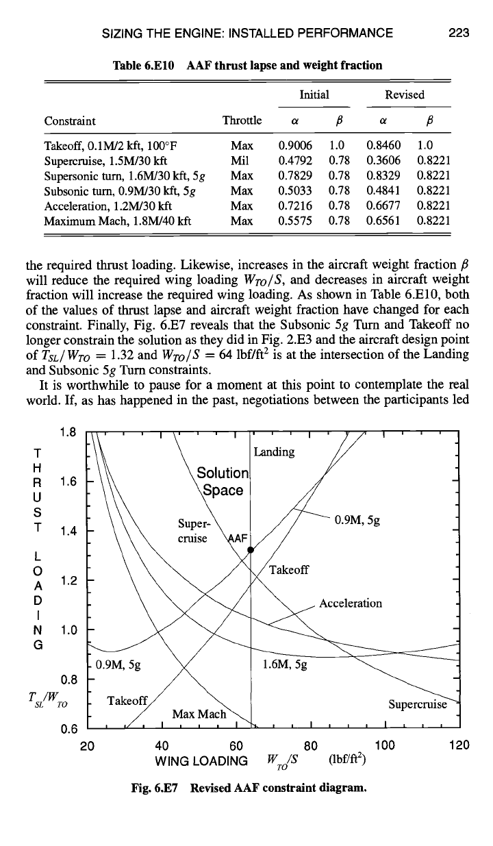
the required thrust loading. Likewise, increases in the aircraft weight fraction fl
will reduce the required wing loading
WTo/S,
and decreases in aircraft weight
fraction will increase the required wing loading. As shown in Table 6.El0, both
of the values of thrust lapse and aircraft weight fraction have changed for each
constraint. Finally, Fig. 6.E7 reveals that the Subsonic 5g Turn and Takeoff no
longer constrain the solution as they did in Fig. 2.E3 and the aircraft design point
of
TSL/WTO
= 1.32 and
Wro/S
= 64 lbf/ft 2 is at the intersection of the Landing
and Subsonic 5g Turn constraints.
It is worthwhile to pause for a moment at this point to contemplate the real
world. If, as has happened in the past, negotiations between the participants led
1.8
T
H
R 1.6
U
S
T 1.4
L
0
A 1.2
D
I
N 1.0
G
0.8
T /W
SL TO
0.6
20
40 60 80
WING LOADING W /S (Ibf/ft 2)
TO
Fig. 6.E7 Revised AAF constraint diagram.
100
120
224 AIRCRAFT ENGINE DESIGN
to a reduction of the Subsonic 5g Tum and/or Landing RFP requirements for the
purpose of reducing thrust loading and engine size, Supercruise would soon be-
come a barrier. This would, of course, lead to another search for the best AAF
engine.
Because the required wing loading is not below our initial estimate of 64 lbf/ft 2,
the revised aircraft design points of
Tsj Wro
= 1.32 and
W~o/S
= 64 lbf/ft 2 are
reconfirmed, and further revision of the required aircraft size and engine thrust is
not necessary at this time. This is a happy moment because engine cycle design can
now come to an end and engine component design can begin. The performance of
the AAF Engine is summarized in the following section before starting the design
of the engine components in Chapter 7.
6.5.3 AAF Engh~e Uninstalled Performance Summary
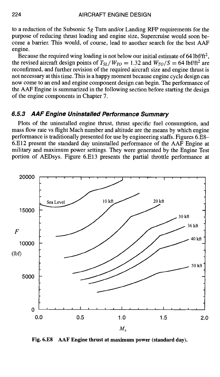
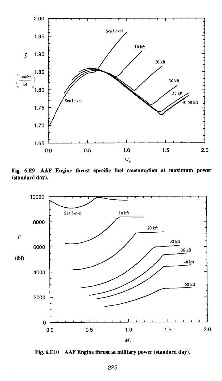
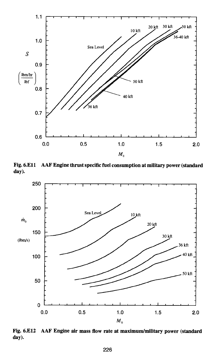
Plots of the uninstalled engine thrust, thrust specific fuel consumption, and
mass flow rate vs flight Mach number and altitude are the means by which engine
performance is traditionally presented for use by engineering staffs. Figures 6.E8-
6.E12 present the standard day uninstalled performance of the AAF Engine at
military and maximum power settings. They were generated by the Engine Test
portion of AEDsys. Figure 6.E13 presents the partial throttle performance at
20000
15000
F
10000
(lb0
5000
30kft
0 I J i i l a i J i I
I I a I I ~ I L I
0.0 0.5 1.0 1.5 2.0
Mo
Fig. 6.E8 AAF Engine thrust at maximum power (standard day).
2.00
1.95
S
1.90
lbm/hr ]1.85
lbf
1.80
1.75
1.70
10 kff
20 kit
30kft
Sea Level ~0 kit
1.65 , ~ , , I , , , , I , , , , I , , , ,
0.0 0.5 1.0 1.5 2.0
Mo
Fig. 6.E9 AAF Engine thrust specific fuel consumption at maximum power
(standard day).
F
(lbf)
10000
8000
6000
4000
2000
Sea Level 10 kfl
20 kfl
_ i / 30 kft
/ ~ 36 kft
0
, , , ,
I
I I I l
I
I I I I
I
I I I I
0.0 0.5 1.0 1.5 2.0
Mo
Fig. 6.El0 AAF Engine thrust at military power (standard
day).
225
1.1
1.0
s
0.9
/
lbf J
0.8
,,,,i,,,,i,,,,i,,,,
20 kit 30 kit ~50 kft
to kn / /.,~
Sea Level
50 kit
40 ktt
0.7
0,6
, ~ ~ = I , , , , I , , , , i
....
0.0 0.5 1.0 1.5 2.0
Mo
Fig. 6.Ell AAF Engine thrust specific
fuel consumption
at military power (standard
day).
250
200 vc]~
Sea Le 10 kft
mo /
150
(lbngs)
100
fill'
50
0 I I ~ ~ I ~ ~ ~ ~ I , , ~ , I , , , ,
0.0 0.5 1.0 1.5 2.0
M0
Fig. 6.E12 AAF Engine air mass flow rate at maximum/military power (standard
day).
226
SIZING THE ENGINE: INSTALLED PERFORMANCE 227
lblrdhr
/
1--;ff-)
2.0
1.8
1.6
1.4
1.2
1.0
0.8
0.6
0.4
0
' ' ' I ' ' ' I ' ' ' I ' ' ' I ' ' ' I ' ' ' I ' ' ' I ' ' '
/o =~ '7 0.;9 1.0 I I 1.2 1.3 15~ "7
/////
Alt = 30 kfl /
, , , ! , , , I , , , I , , , I , , , I I I I I i I I I I I I
2,000 4,000 6,000 8,000 10,000 12,000 14,000 16,000
F (lbf)
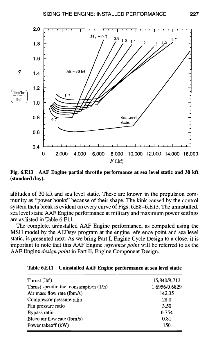
Fig. 6.E13 AAF Engine partial throttle
performance at sea
level static and 30 kft
(standard
day).
altitudes of 30 kft and sea level static. These are known in the propulsion com-
munity as "power hooks" because of their shape. The kink caused by the control
system theta break is evident on every curve of Figs. 6.E8-6.E13. The uninstalled,
sea level static AAF Engine performance at military and maximum power settings
are as listed in Table 6.El 1.
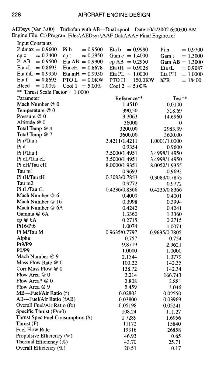
The complete, uninstalled AAF Engine performance, as computed using the
MSH model by the AEDsys program at the engine reference point and sea level
static, is presented next. As we bring Part I, Engine Cycle Design to a close, it is
important to note that this AAF Engine
reference point
will be referred to as the
AAF Engine
design point
in Part II, Engine Component Design.
Table 6.Ell Uninstalled AAF Engine performance at sea level static
Thrust (lbf) 15,840/9,713
Thrust specific fuel consumption (l/h) 1.6956/0.6829
Air mass flow rate (lbm/s) 142.35
Compressor pressure ratio 28.0
Fan pressure ratio 3.50
Bypass ratio 0.754
Bleed air flow rate (lbm/s) 0.81
Power takeoff (kW) 150
228 AIRCRAFT ENGINE DESIGN
AEDsys (Vet. 3.00) Turbofan with AB---Dual spool Date:10/1/2002 6:00:00 AM
Engine File: C:\Program Files\AEDsys\AAF Data\AAF Final Engine.ref
Input Constants
Pidmax = 0.9600 Pi b = 0.9500 Eta b = 0.9990 Pin = 0.9700
cp c = 0.2400 cp t = 0.2950 Gam c = 1.4000 Gam t = 1.3000
PiAB =0.9500 EtaAB =0.9900 cpAB =0.2950 GamAB = 1.3000
EtacL = 0.8693 EtacH = 0.8678 EtatH = 0.9028 EtatL = 0.9087
Eta mL = 0.9950 Eta mH = 0.9950 Eta PL = 1.0000 Eta PH = 1.0000
Etaf = 0.8693 PTOL = 0.0KW PTOH = 150.0KW hPR = 18400
Bleed = 1.00% Cool 1 = 5.00% Coo12 = 5.00%
** Thrust Scale Factor = 1.0000
Parameter Reference** Test**
Mach Number @ 0 1.4510 0.0100
Temperature @ 0 390.50 518.69
Pressure @ 0 3.3063 14.6960
Altitude @ 0 36000 0
Total Temp @ 4 3200.00 2983.39
Total Temp @ 7 3600.00 3600.00
Pi r/Tau r 3.4211/1.4211 1.0001/1.0000
Pi d 0.9354 0.9600
Pi ffrau f 3.5000/1.4951 3.4998/1.4950
Pi cLfrau cL 3.5000/1.4951 3.4998/1.4950
Pi cH/Tau cH 8.0000/1.9351 8.0052/1.9355
Tau ml 0.9693 0.9693
Pi tH/Tau tH 0.3083/0.7853 0.3083/0.7853
Tau m2 0.9772 0.9772
Pi tL/Tau tL 0.4236/0.8366 0.4235/0.8366
Mach Number @ 6 0.4000 0.4001
Mach Number @ 16 0.3998 0.3994
Mach Number @ 6A 0.4242 0.4241
Gamma @ 6A 1.3360 1.3360
cp @ 6A 0.2715 0.2715
Ptl6/Pt6 1.0074 1.0071
Pi M/Tau M 0.9635/0.7797 0.9635/0.7805
Alpha 0.757 0.754
Pt9/P 9 9.8719 2.9621
P0/P9 1.0000 1.0000
Mach Number @ 9 2.1544 1.3779
Mass Flow Rate @ 0 103.22 142.35
Corr Mass Flow @ 0 138.72 142.34
Flow Area @ 0 3.214 166.743
Flow Area* @ 0 2.808 2.881
Flow Area @ 9 5.459 3.046
MB--Fuel/Air Ratio (f) 0.02803 0.02550
AB--Fuel/Air Ratio (fAB) 0.03800 0.03969
Overall Fuel/Air Ratio (fo) 0.05198 0.05241
Specific Thrust (F/m0) 108.24 111.27
Thrust Spec Fuel Consumption (S) 1.7289 1.6956
Thrust (F) 11172 15840
Fuel Flow Rate 19316 26858
Propulsive Efficiency (%) 46.93 0.65
Thermal Efficiency (%) 43.70 25.71
Overall Efficiency (%) 20.51 0.17
SIZING THE ENGINE: INSTALLED PERFORMANCE 229
References
]In-Flight Thrust Determination and Uncertainty,
Society of Automotive Engineers Spe-
cial Publication 674, Society of Automotive Engineers, Warrendale, PA, 1986.
2Oates, G. C.,
The Aerothermodynamics of Gas Turbine and Rocket Propulsion,
3rd. ed.,
AIAA Education Series, AIAA, Reston, VA, 1997.
3Mattingly, J. D.,
Elements of Gas Turbine Propulsion,
McGraw-Hill, New York,
1996.
4Oates, G. C. (ed.), The
Aerothermodynamics of Aircraft Gas Turbine Engines,
AFAPL-
TR-78-52, Wright-Patterson AFB, Ohio, July 1978.
5Oates, G. C. (ed.),
Aircraft Propulsion Systems Technology and Design,
AIAA Education
Series, AIAA, Washington, DC, 1989.
6Oates, G. C. (ed.),
Aerothermodynamics of Aircrafi Engine Components,
AIAA Educa-
tion Series, AIAA, New York, 1985.
7Swavely, C. E., and Soilean, J. E, "Aircraft Aftbody/Propulsion System Integration for
Low Drag," AIAA Paper 72-1101, 1972.
PART II
Engine Component Design
7
Engine Component Design:
Global and Interface Quantities
7.1 Concept
This chapter plays a pivotal role because it provides the bridge between treating
the propulsion system as a whole and beginning the design of those parts that have
traditionally been identified as components and subsystems. No standard or com-
pletely comprehensive list of components and subsystems is available because they
differ from company to company and engine to engine, but any reasonable collec-
tion would include at least the following components:
1) inlet
2) fan and booster
3) propeller and variable pitch control
4) low-pressure compressor (LPC)
5) high-pressure compressor (HPC)
6) main or primary burner
7) high-pressure turbine (HPT)
8) low-pressure turbine (LPT)
9) free or power turbine
10) mixer
11) afterburner or augmentor exhaust nozzle
12) and thrust reverser.
The subsystems would include the following:
I) nacelle
2) fuel delivery system
3) instrumentation and controls
4) starting and ignition system
5) structure
6) shafts, bearings, and seals
7) accessory gearbox and drive
8) propeller gearbox
9) lubrication and cooling systems
10) and fire control.
Within any engine company each of these is represented by a team of experts,
many of whom have dedicated their entire careers to success. It is good to remember
that, although the propulsion industry has found by experience that this breakup is
most effective for management, no one component or subsystem is free from the
influence of all of the others. The entire engine is coupled through aerodynamics,
thermodynamics, structures, and controls; therefore, integration is a vital activity
at all stages of design and development. One should also approach each component
and subsystem with a minimum of prejudice about its importance to the whole.
233
234 AIRCRAFT ENGINE DESIGN
For example, the instrumentation and controls package ordinarily accounts for
20-30% of the total cost and weight of the engine, and a fuel delivery system
that allows some trapped fuel to drain into the burner after the engine has stopped
running increases the danger of internal fire and explosion.
Component and subsystem design can commence now because there is an abun-
dance of "inside information" about the chosen design point engine (referred to
in Part I as the reference point). By running AEDsys Performance computations
at the desired flight conditions and throttle settings, the behavior of the flow prop-
erties at the interfaces between the flowpath components as well as across these
components can be established.
This supplies the quantitative information necessary to allow the separate design
of each flowpath component to begin, which, in turn, will generate the require-
ments and constraints for the supporting subsystems. Equally important to the
remainder of the project is the institution of a systematic approach to component
and subsystem integration. There must be methods and procedures to ensure that
everyone shares the same assumptions and goals. Frequent updating of quantitative
information and communication about problems and lines of attack are key ingre-
dients of the process. You would be amazed to discover how easily communication
breaks down and how severe are the consequences.
7.2 Design Tools
The emphasis here is on assembling a complete set of flow quantities at each
engine station as well as several derived properties of interest. You will find it
helpful to recognize the diverse roles played in the following discussions by the
engine reference stations (see Sec. 4.2.1). First, each is the interface between two
sequential flowpath components. Second, each is the entrance to one component
and the exit for another. Third, any two successive engine stations provide the
boundary conditions for an individual flowpath component.
Systematic procedures for calculating the most important interface and other
derived quantities will now be developed. The source document is a complete set
of ONX engine design point (reference point of Part I) computations, such as that
of the Air-to-Air Fighter (AAF) Engine presented in Fig. 7.1. Please note for the
final time that these computations, as well as all of the ensuing global and inter-
face quantities, are based on the MSH (modified specific heat) model described in
Sec. 4.2.7.
7.2.1 Total Pressure, Total Enthalpy, and Total Temperature
Total pressure and total temperature are of special importance to the engine
designer because they are the most thermodynamically meaningful and far easier
to measure than their corresponding static properties. The total pressure and total
enthalpy are found directly from the definitions of Sec. 4.2.3.
For example, the total pressure at the interface between the high-pressure com-
pressor and the burner is given by the expression
Pt3 = P0 rer red reel Zrcn = P0 rer Jrd rec (7.1)