Massoud M. Engineering Thermofluids: Thermodynamics, Fluid Mechanics, and Heat Transfer
Подождите немного. Документ загружается.


302 IIIb. Fluid Mechanics: Incompressible Viscous Flow
[25 / (
π
D
2
/4)] = 0.59 D
2/3
(250/5 × 5280)
0.5
/0.012
Solving for D, we find D
M
= 2 ft or 24 inches. The reader should now try the
Darcy-Weisbach formula.
Finding the pipe diameter, D, from the Darcy equation requires iteration as we
should solve Equations IIIb.3.4 and IIIb.3.5 simultaneously. Another way to
avoid iteration is to use the Swamee and Jain’s correlation:
04.0
2.5
9.4
75.4
2
25.1
h
V
h
V
66.0
»
»
»
¼
º
«
«
«
¬
ª
¸
¸
¹
·
¨
¨
©
§
+
¸
¸
¹
·
¨
¨
©
§
=
ff
g
L
g
L
D
νε
IIIb.3.10
where
ε
is in ft, V
is in ft
3
/s, L is in ft, g = 32.2 ft/s
2
, h
f
in ft,
ν
in ft
2
/s, and D is
in ft. Note that Equation IIIb.3.10 is applicable for 10
– 6
≤
ε
≤ 0.02 and 3 × 10
3
≤ Re ≤ 3 × 10
6
.
Example IIIb.3.5. Solve Example IIIb.3.4 using the Swamee and Jain’s correla-
tion. Use water at T = 65 F.
Solution: From Table IIIb.3.1 we find
ε
= 0.00015 ft. Also for water, v = 0.041
ft
2
/hr = 1.13E-5 ft
2
/s. We now substitute in Equation IIIb.3.10:
2
1.25 4.75 9.4 5.2 0.04
26,399.7(25) 26,399.7
0.66[0.00015 ( ) 1.13E 5 (25) ( ) ] 1.854 ft
32.2 250 32.2 250
D =+−×=
××
= 22.3 in
Pressure Drop Associated with Fittings and Valves
Earlier we studied pressure drop in straight pipes due to the viscosity of the fluid
and the surface condition of the pipe wall. This is known as skin friction. We
now consider other conditions that also result in pressure drop by disturbing the
flow such as twist, turn, or partial obstruction of the flow. These may result in
flow separation and consequently irreversible energy loss to the fluid flow. Simi-
lar to the Darcy pressure drop, this also results in unrecoverable pressure drop.
Losses due to twist, turn, and flow obstruction are generally due to the presence
of valves and fittings such as reducers, enlargers, bends, T for flow division, and
invasive flowmeters. The losses due to the fittings and valves are referred to as
the minor losses. The term minor should not be taken literally as depending on the
flow condition the pressure drop due to the presence of pipe fittings, flowmeters,
and valve may by far surpass the pressure drop caused by the skin friction.
Using an electrical engineering analogy, fluid flow is similar to electric current,
pressure loss is equivalent to voltage difference and disturbance to the flow is
equivalent to electrical resistance. The term “hydraulic resistance” for such dis-
turbances to the flow is therefore well suited. To be consistent with Darcy pres-
3. Pressure Drop in Steady Internal Incompressible Viscous Flow 303
sure drop (Equation IIIb.3.7), ∆P due to fittings and valves is also expressed in
terms of specific kinetic energy:
2
2
2
22
2
K
2
V
K
2
K
A
m
A
V
P
ρ
ρρ
===∆ IIIb.3.11
where K is referred to as loss coefficient. Since combined molecular and turbulent
viscosity is the mechanism that converts mechanical work into heat, it is difficult
to find analytical solutions to the hydraulic resistance-induced pressure drops. For
this reason, each specific hydraulic resistance must be evaluated separately. Ex-
perimental data are obtained for various hydraulic resistance configurations.
These data are generally correlated in terms of dimensionless numbers to account
for the type of fluid (density and viscosity), flow properties (flow velocity), and
the hydraulic resistance geometry (diameter, thickness, etc.) These correlations
can be found in such handbooks as Idelchik, Lyons, and Crane.
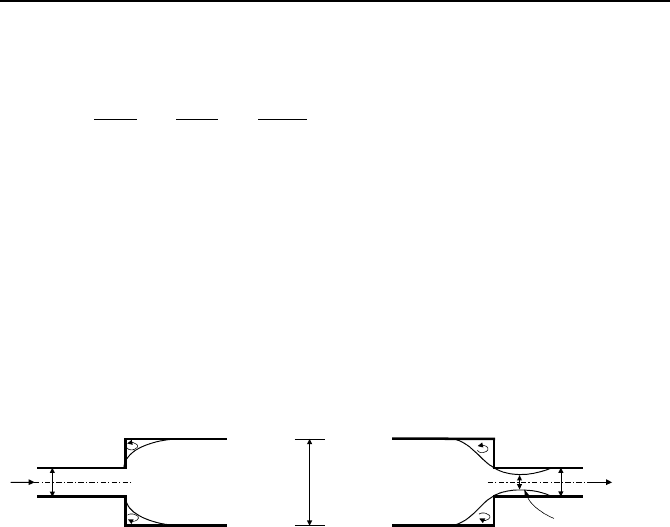
D
Vena
Contracta
K
c
= 0.5[1 - (d/D)
2
]
V
d
V
d
d
min
K
e
= [1 - (d/D)
2
]
2
Figure IIIb.3.2. Loss coefficient associated with sudden change in flow area
As shown in Figure IIIb.3.2, a sudden expansion occurs in a flow when a pipe
is connected to a larger diameter pipe without gradual increase in diameter. This
results in flow separation downstream of the connection edge. In this case, the
loss coefficient is derived as (Example IIIb.3.6):
22
])/(1[K Dd
e
−=
This figure also shows a sudden contraction at a junction between two pipe sizes.
In a sudden contraction, flow separation in the downstream pipe causes the main
stream to contract through a minimum diameter, referred to as vena contracta.
The loss coefficient for sudden contraction is:
])/(1[5.0K
2
Dd
c
−=
For both cases of sudden expansion and contraction, the corresponding head loss
is found in terms of the velocity in the smaller pipe (i.e.,
gV
d
2/Kh
2
= ).
304 IIIb. Fluid Mechanics: Incompressible Viscous Flow
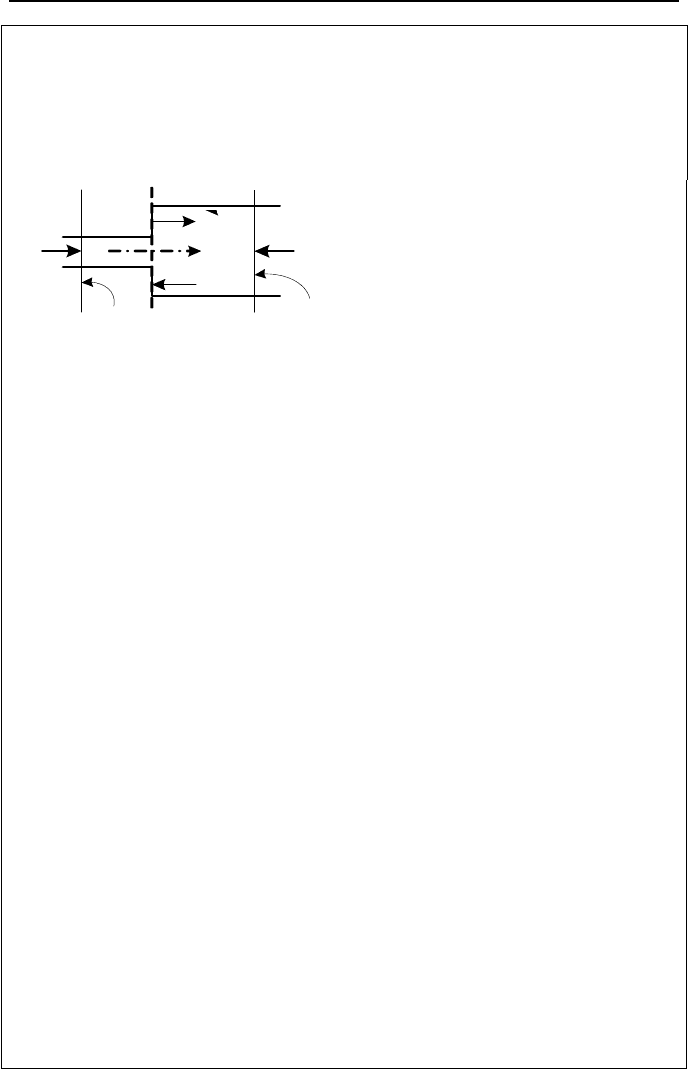
Example IIIb.3.6. Derive the loss coefficient for a sudden expansion.
Solution: To find K for a sudden expansion, we write the steady-state form of the
momentum equation. To do this, we consider a control volume the extent of
which is from cross section 1 to cross section 2. The surface forces acting on this
control volume are pressure and shear forces. Hence, we can write:
A
1
1 j
F
1
F
j
F
t
A
2
2
F
2
)()(
2
11
2
221221
VAVAVVmFFFF
jt
−=−=+−−
ρ
where F
1
= P
1
A
1
, F
2
= P
2
A
2
, F
j
is a force due to the interaction between the fluid
and the channel wall at the expansion plane j, acting on area A
2
– A
1
and F
t
is the
shear force. To reduce the number of unknowns, let’s assume that the friction
force in the short distance between planes 1 and 2 is negligible (i.e., F
t
§ 0).
Hence, the momentum equation simplifies to:
)()(
2
11
2
22122211
VAVAAAPAPAP
j
−=−+−
ρ
Still, we have more unknowns than equations. To get rid of P
j
, we note that pres-
sure at 1 is practically the same as pressure at cross section j due to the short dis-
tance between cross sections 1 and j, the constant flow area, and the zero shear
force assumption. Substituting for P
j
= P
1
we get:
)()(
2
11
2
22212
VAVAPPA −=−
ρ
Relating velocities by the continuity equation, V
2
= V
1
A
1
/A
2
and substituting, we
get:
[
]
21
2
21
2
12
2
11
2
2221
/)/(/)( AAAAVAVAVAPP −=−=−
ρρ
(1)
We also note that Equation IIIa.3.30 gives the relation between P
1
– P
2
and head
loss with Z
1
= Z
2
and h
s
= 0:
f
gVVPP
h2/)(
2
1
2
221
ρρ
+−=−
(2)
We substitute for P
1
– P
2
from Equations (2) into Equation (1) and solve for h
f
:
()()
[
]
()
gVAAAA
f
2///21h
2
1
2
2121
+−=
(3)
By comparing with
gV
f
2/Kh
2
1
=
we find K
≡
(1 – A
1
/A
2
)
2
. Equation (3) is
known as the Borda-Carnot equation.
3. Pressure Drop in Steady Internal Incompressible Viscous Flow 305
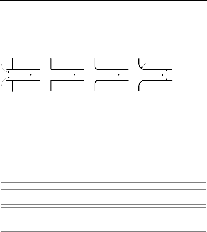
In a sudden contraction, if the upstream diameter approaches infinity, the loss
coefficient is associated with “pipe entrance”. As shown in Figure IIIb.3.3, the
smoother the entrance to a pipe, the lower the loss coefficient. For example, in the
reentrant type, the pipe penetrates the flow field, causing perturbation of stream-
lines, some flow separation, and large head loss.
R = 0.2 d
d
Reentrant
K = 0.78
Sharp - Edged
K = 0.5
Slightly Rounded
K = 0.25
Well Rounded
K = 0.05
Figure IIIb.3.3. Loss coefficient associated with various pipe entrances
Table IIIb.3.2 (Crane) gives the friction factor for clean commercial steel pipe
for fully turbulent flow in terms of nominal pipe size. To find loss coefficient in
various valves and fittings (Table IIIb.3.3), we can either calculate the friction fac-
tor or use approximate value from Table IIIb.3.2 based on the pipe diameter.
Table IIIb.3.2. Turbulent flow friction factor for clean commercial steel pipe
Nominal Size (inch) 1/2” 3/4” 1” 1 ¼” 1 ½” 2” 2 ½” , 3”
Nominal Size (mm) 15 20 25 32 40 50 65 - 80
f 0.027 0.025 0.023 0.022 0.021 0.019 0.018
Nominal Size (inch) 4” 5” 6” 8” - 10” 12” - 16” 18” - 24”
Nominal Size (mm) 100 125 150 200 - 250 300 - 400 450 - 600
f 0.017 0.016 0.015 0.014 0.013 0.012
The loss coefficient (K) for a variety of valves and fittings is presented in Ta-
ble IIIb.3.3. In this table, the loss coefficient is given in terms of an equivalent
length, K = fL
e
/D. Dependence of K on D, for flow through valves and fittings, is
similar to the dependence of f on D, for flow in straight pipes. Hence, the L
e
/D
term tends towards a constant value for various pipe sizes of a given type of fit-
ting. For example, consider flow through a fully opened gate valve installed on a
2 inch diameter pipe (K = 8 from Table IIIb.3.3). The L
e
associated with this
valve is found from L
e
/D = K/f = 8/0.019 = 421. Thus L
e
= 421D = 70 ft where f is
estimated from Table IIIb.3.2 as f = 0.019.
Pipe and tube data are provided in Tables A.III.1 through A.III.3. In summary,
total pressure drop is the summation of that given by Equations IIIb.3.7 and
IIIb.3.11:
306 IIIb. Fluid Mechanics: Incompressible Viscous Flow
2
22
2
K
2
K
A
m
D
L
f
V
D
L
fP
ρ
ρ
¸
¹
·
¨
©
§
+=
¸
¹
·
¨
©
§
+=∆
¦¦
IIIb.3.12
Equation IIIb.3.12 can alternatively be written as:
2
2
2
2
2
22
2
'
2
V'
2
V
2
A
m
D
L
f
A
D
L
f
A
D
LL
f
V
D
L
D
L
fP
ee
ρ
ρρρ
==
¸
¹
·
¨
©
§
+
=
¸
¹
·
¨
©
§
+=∆
IIIb.3.13
The frictional losses in fittings and valves are often referred to as form losses.
Note that we may write Equation IIIb.3.13 as:
K
2
P
Am
∆
=
ρ
IIIb.3.14
where K = fL/D +
ΣK
i
where index i refers to various fittings and valves on the
piping system. As discussed in Chapter IIIc, Equation IIIb.3.14 may also be ap-
plied to compressible flow with some modifications.
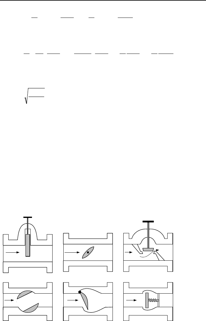
Application and Various Types of Valves
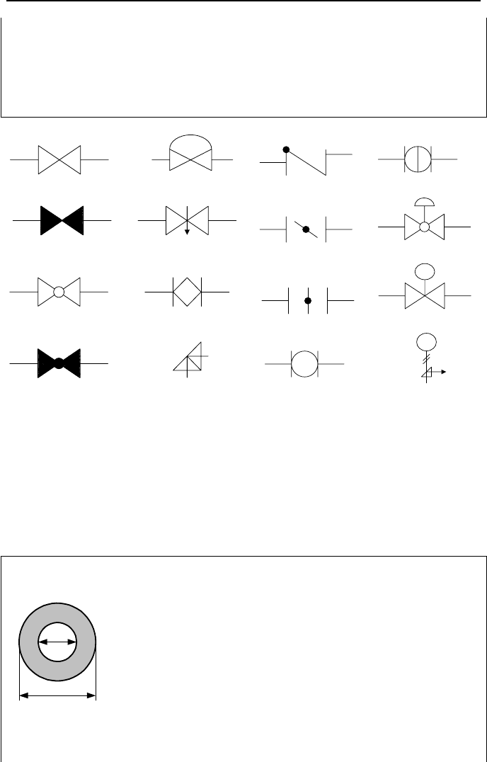
Schematics of various control and check valves are shown in Figure IIIb.3.4. De-
sign details of a chemical, food processing, or power plant including the inter-
relationship of various systems and components are generally documented in so
called Piping & Instrumentation Diagrams (P&IDs). To simplify drafting and the
application of the P&IDs, symbols representing various components are devised.
For example, Figure IIIb.3.5 shows symbols used to represent various types of
valves. We can divide valves into two categories, flow control valves and pres-
sure control valves. We first discuss flow control valves.
Gate Valve
Butterfly Valve
Globe Valve
Ball Valve
Swing Check Valve Push Check Valve
Figure IIIb.3.4. Schematics of various valves

3. Pressure Drop in Steady Internal Incompressible Viscous Flow 307
A gate valve is generally used to isolate components. As such, a gate valve is
either fully open or fully closed. On the other hand, to throttle the flow, globe
valves are utilized. Expectedly, globe valves are associated with much higher-
pressure drop for the flow than open gate vales. Other flow control valves include
butterfly valves, ball valves, and needle valves. Directional valves include various
types of check valves. For example, in a tilting disc and a swing check valve, the
disc is readily lifted in the flow direction due to the flow momentum acting on the
disc. However, if flow reverses, the pressure exerted on the disc would keep the
valve tightly shut.
Safety valves (SVs), to control pressure, are generally spring loaded. If the
pressure exceeds the high-pressure set point, the valve will lift and is then reset
when pressure drops below the low-pressure set point. Pilot Operated Relief
Valves (PORVs) can be manually or remotely operated (lifted) to relieve pressure.
PORVs operate on a minimum and maximum pressure differential. In remotely
operated valves, the action of obstructing or allowing the flow of fluids can be ac-
complished by a driver to change the position of the gate, disc, plunger, etc.
Valves equipped with such drivers are generally known as motor operated valves
(MOVs). Depending on the type and size of a valve, the driver is an electric mo-
tor, an air operated (pneumatic) system, or electromagnetic (solenoids). For ex-
ample, PORVs are generally solenoid valves.
Table IIIb.3.3. Loss coefficient (K) in L
e
/D for valves and fittings
Category Item Loss Coefficient (K/f)
Elbow 90 Threaded 30
45 Threaded 16
90 Welded 14
45 Welded 10
Tee Line Flow 20
Branch Flow 60
Valve Gate (fully open) 8
Gate (75% open) 35
Gate (50% open) 160
Gate (25% open) 900
Swing check (fully open) 50
Lift check (fully open) 600
Globe (fully open) 340
Angle (fully open) 150
Ball (fully open) 3
Butterfly (fully open) 50
Valve flow rate is also defined in terms of the flow coefficient C
v
(also known
as valve sizing coefficient) being the ratio of the theoretical and the actual flow
rates. In applications however, C
v
for the flow of incompressible fluid is defined
as the flow rate of water in GPM at 60 F and at a pressure drop of 1 psi across a
valve (Crane). The metric equivalent of flow coefficient is flow factor K
v
, defined
as the flow rate of water in m
3
/h at 20 C, which results in a pressure drop of 1 bar.

308 IIIb. Fluid Mechanics: Incompressible Viscous Flow
Having the C
v
of a valve, flow rate through the valve at temperatures other than
60 F (or liquid other than water) and pressure drops other than 1 psi may be cal-
cualted from:
gv
SPC /V ∆=
IIIb.3.15
where S
g
is the liquid specific gravity, ∆P is in psi, and the volumetric flow rate is
in GPM.
Example IIIb.3.7. A valve with a flow coefficient of 1000 results in a pressure
drop of 2 psi (13.8 kPa) across the valve for water flowing at 110 F (43 C). Find
the corresponding flow rate.
Solution: At 15 psia, we find
ρ
(60 F) = 62.4 lbm/ft
3
and
ρ
(110 F) = 61.88
lbm/ft
3
. The flow rate is found from Equation IIIb.3.15 as V
= 1000 ×
[2/(61.88/62.4)]
1/2
= 1420 GPM (89.6 lit/s).
The valve loss, or resistance coefficient, can be expressed as a function of the
valve C
v
and the pipe inside diameter by substituting for the definition of C
v
into
Equation IIIb.3.11, which results in
24
/891K
v
Cd= where pipe inside diameter d
is in inches. We may also find C
v
for a given K and d from C
v
= 29.84d
2
/K
0.5
.
Example IIIb.3.8. A valve of C
v
= 500 is installed on a 5-inch pipe. Find the
valve loss coefficient.
Solution: The corresponding loss coefficient for this valve is found as
23.2500/)5(891/891K
2424
===
v
Cd
Example IIIb.3.9. Find the pressure drop over a half-open gate valve located on
a horizontal 6-inch pipe carrying SAE 10W oil at 92 F and 1000 GPM. (
ε
= 0.025
in,
ν
= 0.00018 ft
2
/s, and S
g
= 0.88).
Solution: In the absence of a pump and for steady flow in a horizontal pipe,
Equation IIIa.3.31 simplifies to Equation IIIb.3.12. For a half-open gate valve, K
= 160f. We find f from:
[][ ]
029.0)025.0/6log(214.1)/(log214.1
22
10
=+=+=
−−
ε
Df
Therefore, K = 0.029 × 160 = 4.64. Flow area is: A =
π
(6/12)
2
/4 = 0.196 ft
2
Flow rate is: V
= 1000/(60 × 7.481) = 2.228 ft
3
/s. Flow density is:
ρ
= 62.4 ×
0.88 = 54.9 lbm/ft
3
3. Pressure Drop in Steady Internal Incompressible Viscous Flow 309
Pressure drop becomes ∆P = 4.64× 54.9 (2.228)
2
/[2 × 32.2 × 0.196
2
] = 511 lbf/ft
2
= 3.5 psi.
Checking on Re to ensure flow is turbulent; Re = [2.228 × (6/12)]/[0.00018 ×
0.196) = 3.2E4 > 4000
Note that from Figure IIIb.3.1, for
ε
/D = 0.004 and Re = 3.2E4, we find f § 0.03.
Diaphragm valve
Needle valve
Plug valve
Angle valve
Open Gate valve
Closed Gate valve
Open Globe valve
Closed Globe valve
Check valve
RV
Safety/Relief valve
Control valve
M
Motor Operrated valve
Closed Ball valve
Open Ball valve
Closed Butterfly valve
Open Butterfly valve
Figure IIIb.3.5. Symbols for various valves
Hydraulic diameter (D
h
) is defined for channels having a flow area, different
than pipes and tubes. Since flow area and perimeter for a circle are given as A
flow
=
π
D
2
/4 and P =
π
D, respectively we conclude that A
flow
= PD/4. We use the same
concept of dividing four times flow area by the wetted perimeter for other conduits
to obtain an equivalent diameter D
h
= 4 A
flow
/P
wetted
.
Example IIIb.3.10. Consider an annular conduit between two concentric cylin-
ders of diameters D
1
and D
2
. Find an equivalent diameter for this conduit.
D
1
D
2
Solution: As shown in the figure, the flow area and the wetted perimeter are
found as:
310 IIIb. Fluid Mechanics: Incompressible Viscous Flow
A
flow
=
π
)(
2
1
2
2
DD − /4 and P
wetted
=
π
(D
2
+ D
1
). Therefore,
(
)
()
12
12
2
1
2
2
4/
4
DD
DD
DD
D
h
−=
+
−
=
π
π
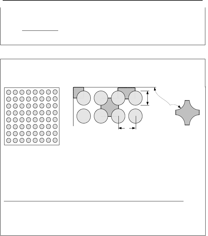
Example IIIb.3.11. In a BWR, fuel rods are arranged in a square array within a
fuel assembly. Find the hydraulic diameter for an interior, side, and corner sub-
channel as shown in the figure.
32
1
D
s
Solid
boundary
Interior subchannel
1: Interior subchannel
3:
Corner subchannel
2: Side subchannel
Solution: With respect to the interior subchannel, we note that the control surface
is bounded by the surface of the four surrounding fuel rods and the gap between
the rods. The wetted perimeter consists only of the solid surfaces (i.e., the four
quadrants of the four surrounding rods, as the gap is only an imaginary boundary).
These are summarized in the table where D is the fuel rod outside diameter and s
is the rod pitch.
No. Type Perimeter Flow Area Hydraulic diameter
1 Interior
π
Ds
2
–
π
D
2
/4 4[s
2
–
π
D
2
/4]/
π
D
2 Side (
π
D/2) + s [s
2
–
π
D
2
/4]/2 2[s
2
–
π
D
2
/4]/
[(
π
D/2) + s]
3 Corner (
π
D/4) + s [s
2
–
π
D
2
/4]/4 [s
2
–
π
D
2
/4]/
[(
π
D/4) + s]
where we have assumed the rod to wall distance to be half of the rod to rod pitch.
4. Steady Incompressible Viscous Flow in Piping Systems
In this section we study the internal flow of incompressible viscous fluids in pipe-
lines under steady-state conditions. We first begin with the flow analysis in a sin-
gle-path system, the most familiar example of which is pumping liquids from a
suction reservoir to a discharge reservoir, as shown in Figure IIIb.4.1. Gas and oil
pipelines are examples of single-path systems. The flow path may consist of any
number of valves, fittings, and instruments such as pressure gages, flowmeters,
temperature probes, etc.
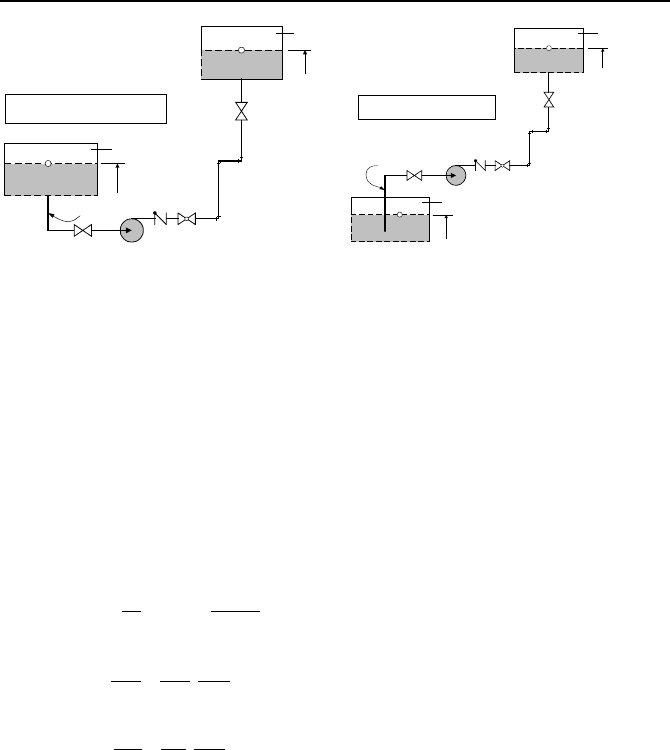
4. Steady Incompressible Viscous Flow in Piping Systems 311
P
A
A
Z
A
P
B
Z
B
B
Suction Head
P
A
and P
B
are maintained
throughout the pumping process
Z
B
P
A
A
Z
A
P
B
B
Suction Lift
P
A
and P
B
are maintained
throughout the pumping process
Figure IIIb.4.1. Pumping liquid in a single path system
To analyze such systems, we may apply Equation IIIb.3.31 between points A and
B, located on the liquid surface of the suction and discharge reservoirs, respec-
tively. Alternatively, we may use Equation IIIa.3.44 in steady-state resulting in:
accvelfricgravstatpump
PPPPP
−
∆+∆+∆+∆=∆ IIIb.4.1
The definition of various differential pressure terms in Equation IIIb.4.1 is as fol-
lows:
ABstat
PPP −=∆
()
ABgrav
ZZgP −=∆
ρ
2
2
2
)K(
A
m
D
L
fP
fric
ρ
¦
+=∆
°
°
¯
°
°
®
−=∆
−=∆
2
2
12
2
22
]
11
[
2
]
11
[
A
m
P
m
AA
P
acc
AB
vel
ρρ
ρ
,
Writing the momentum equation in terms of differential pressures makes compre-
hension of the momentum equation intuitively simple. The left side of Equa-
tion IIIb.4.1 represents pressure increase in the flow while moving from pump
suction to pump discharge due to momentum transfer from the pump impeller to
the flow. In steady-state operation, this increase in pressure must overcome fric-
tional losses and provide for pumping the liquid to a higher elevation. The first
term on the right side,
∆P
stat
= P
B
– P
A
, is the difference in static pressure of point
A and point B. If pressure at the suction reservoir is higher than pressure in the
discharge reservoir, this term would assist the pump head and if there is no pump,
this term would provide the driving force.
The second term in the right side is pressure difference due to gravity (
∆P
grav
).
A significant portion of ∆P
pump
is used to lift liquid from point A and deliver it to