Massoud M. Engineering Thermofluids: Thermodynamics, Fluid Mechanics, and Heat Transfer
Подождите немного. Документ загружается.

262 IIIa. Fluid Mechanics: Single-Phase Flow Fundamentals
the terms in the brackets sum up to zero. Since in the next section we will also de-
rive the Bernoulli equation from the conservation equation for momentum, we
leave the discussion about the Bernoulli equation to the next section and here we
only concern ourselves with the terms in the bracket:
[]
)( quuww
ievs
−−++
In order for this bracket to sum up to zero, we should have no viscous work, no
shaft work and show that
0)( =−− quu
ie
. Let’s see under what circumstance
this parenthesis becomes zero. Obviously one case is when
ie
uu = and q = 0
(i.e., for adiabatic flow). Another case is when
quu
ie
=− . The latter condition
indicates that even if heat transfer is involved for the flow going from point
i to
point
e, as long as the heat transfer is equal to the increase in the flow specific in-
ternal energy, still the terms in the parenthesis sum up to zero. This condition ex-
its for inviscid and incompressible flow.
If the term
0)( ≠−− quu
ie
we cannot then use the Bernoulli equation. To
take into account the effects of the parenthesis when not summing up to zero, we
retain this term in Equation IIIa.3.27. However, for simplicity, we represent the
unrecoverable energy loss as
fie
gquu h)( =−− . Term h
f
is referred to as the un-
recoverable head loss. Substituting this definition, Equation IIIa.3.27 becomes:
()
2
hh 0
2
exit
exit
sf
inlet
inlet
dP dV
g d d gdZ
ρ
´
µ
µ
µ
¶
§·
++ ++ =
¨¸
©¹
³
IIIa.3.28
where in Equation IIIa.3.28, we ignored the shear work in comparison with the
shaft work and we wrote the shaft work as head. Carrying out the integral, Equa-
tion IIIa.3.28 is further simplified to:
For Steady Compressible Flow:
³
0)/(
1
)(
2
)hh(
22
=+−+
−
++
ρ
dP
g
ZZ
g
VV
ie
ie
fs
IIIa.3.29
Or alternatively,
For Steady Incompressible Flow:
0)(
1
)(
2
)hh(
22
=−+−+
−
++
i
i
e
e
ie
ie
fs
PP
g
ZZ
g
VV
ρρ
IIIa.3.29
For incompressible flow, density can be treated as a constant (
ρ
e
=
ρ
i
) and Equa-
tion IIIa.3.29 becomes:
For Steady Incompressible Flow:
fe
ee
i
ii
Z
g
VP
g
Z
g
VP
g
hh
2
1
2
1
s
22
++++=++
ρρ
IIIa.3.30
3. Conservation Equations 263
Equation IIIa.3.30 is the basis for the field of hydraulics. In this equation, each
term has the dimension of length and all terms are written in terms of head. Rear-
ranging Equation IIIa.3.30, we find
fei
ei
ei
ZZ
VV
g
PP
g
hh)()
22
(
1
)(
1
s
22
+=−+−+−
ρ
IIIa.3.31
In Equation IIIa.3.31, the first term in the left side is the pressure head, the second
term is the velocity head, and the third term is the elevation head. In the right
side, the first term is the shaft head (pump head with –h
p
or turbine head with +h
t
)
and the second term is the head loss. The velocity head is a recoverable head
whereas the head loss, as the name implies, is unrecoverable. If the fluid is fric-
tionless, then h
f
= 0. These terms, especially the head loss for internal flow, are
discussed in detail in Chapter IIIb.
It is important to emphasize that in this derivation we have been consistent with
the sign convention we defined in Chapter IIa (see Problem 60). Hence +h
s
should
be chosen if the control volume to which Equation IIIa.3.31 is applied includes a
turbine. Similarly, –h
p
should be chosen if the control volume to which Equa-
tion IIIa.3.31 is applied includes a pump or compressor. Regarding h
f,
it always
represents a negative value since friction produces heat, which is transferred to the
surroundings. Hence, +h
f
should always be used in Equation IIIa.3.30 or IIIa.3.31.
Equation IIIa.3.31 may also be written as:
)
2
(hh)
2
(
2
s
2
e
e
efi
i
i
gZ
V
PgggZ
V
P
ρ
ρ
ρρρ
ρ
+++=−++
IIIa.3.32
Means of calculating h
f
are discussed in Chapter IIIb. If friction is negligible and
there is no shaft work, Equation IIIa.3.31 simplifies to:
Steady ideal Flow, and no Work:
e
ee
i
ii
gZ
VP
gZ
VP
++=++
22
22
ρρ
IIIa.3.33
This is the famous Bernoulli equation, first introduced in Bernoulli’s Hydrody-
namics, published in 1738. The Bernoulli equation is also applicable to a com-
pressible fluid as long as flow velocity remains about 30% of the speed of sound
in the fluid. Cautions on the use of this equation are discussed later in this section.
Equation IIIa.3.33 shows that the summation of pressure work, kinetic energy, and
potential energy for steady ideal flow with no shaft work remains a constant along
the streamlines.
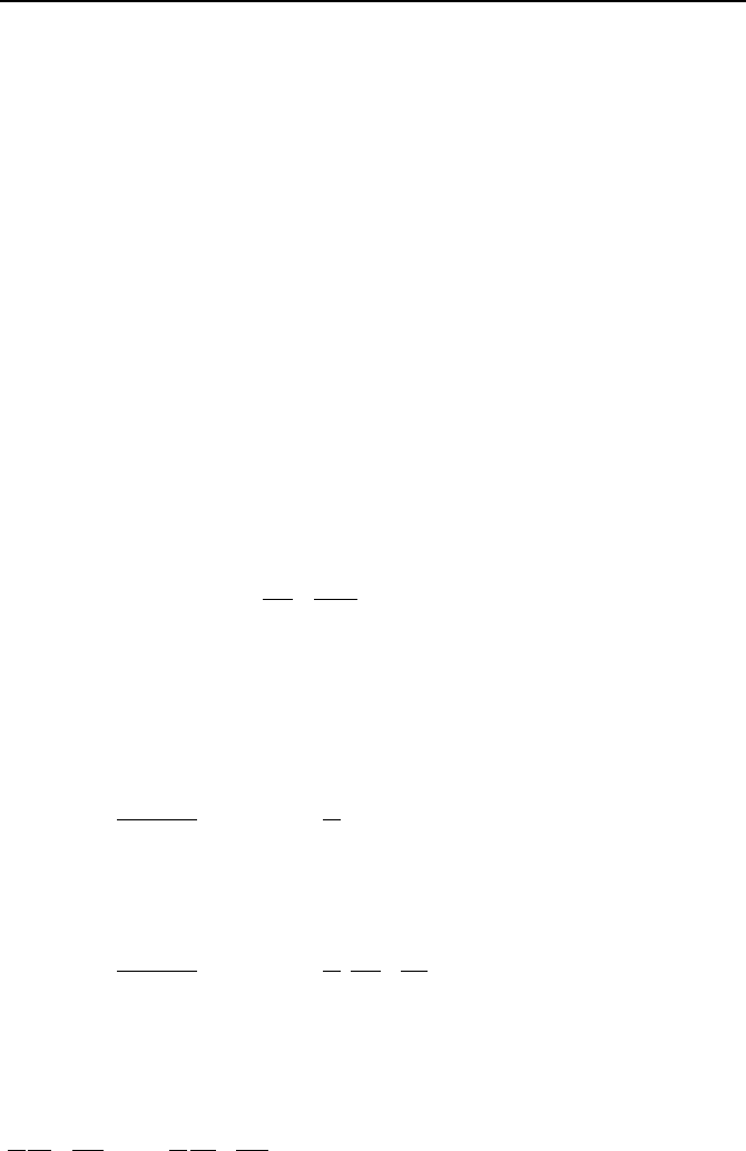
Terms in Equation IIIa.3.31 are divided by g to obtain head and the equation is
then applied to a flow path as graphically shown in Figure IIIa.3.4(a). Note that
the energy grade line (EGL) represents the summation of all the terms and the hy-
draulic grade line (HGL) represents the summation of pressure and elevation
terms. We assume that the flow path and the bends in Figure IIIa.3.4(a) are
smooth and frictionless.
264 IIIa. Fluid Mechanics: Single-Phase Flow Fundamentals
Example IIIa.3.14. Flow of water enters the conduit shown in Figure IIIa.3.4(b)
at a rate of 10 ft
3
/s (283 lit/s). For the given data, find the pressure head at point 2.
Assume frictionless flow path. Data: D
1
= 1 ft (0.3 m), D
2
= 2 ft (0.6 m), Z
1
= 10
ft (3 m), Z
2
= 20 ft (6 m)and (Pressure head)
1
= 25 ft (7.6 m).
Solution: We first find water velocity at points 1 and 2 using V = V
/A =
4 V
/
π
d
2
. Hence, V
1
= 4 × 10/
π
× 1
2
= 12.73 ft/s (3.88 m/s) and V
2
= 4 × 10/
π
× 2
2
= 3.18 ft/s (0.97 m/s). Equation IIIa.3.33 in terms of head is:
2
2
22
1
2
11
22
Z
g
V
g
P
Z
g
V
g
P
++=++
ρρ
Substituting values, we find,
25 + (12.73)
2
/(2 × 32.2) + 10 = (P
2
/
ρ
g) + (3.18)
2
/(2 × 32.2) + 20.
Thus, (P
2
/
ρ
g) = 17.36 ft (5.3 m).
Z
2
Z
1
g
V
2
2
1
g
V
2
2
2
Energy Grade Line (EGL)
H
y
d
r
a
u
l
i
c
G
r
a
d
e
L
i
n
e
(
H
G
L
)
2
1
Total Head
Piezometric Head
P
2
ρ
g
P
1
ρ
g
Datum Plane
1
2
Z
1
Z
2
P
2
ρ
g
(V
1
)
2
2g
2g
(V
1
)
2
Energy Grade Line
H
y
d
r
a
u
l
i
c
G
r
a
d
e
L
i
n
e
P
1
ρ
g
(a) (b)
Figure IIIa.3.4. (a) An arbitrary flow path representing HGL. (b) Figure for Exam-
ple IIIa.3.14
Having derived the Bernoulli equation from the energy equation with the im-
posed restrictions, we set out to derive the Bernoulli equation from the momentum
equation. However, we first need to learn about the fluid rotation.
Fluid Rotation
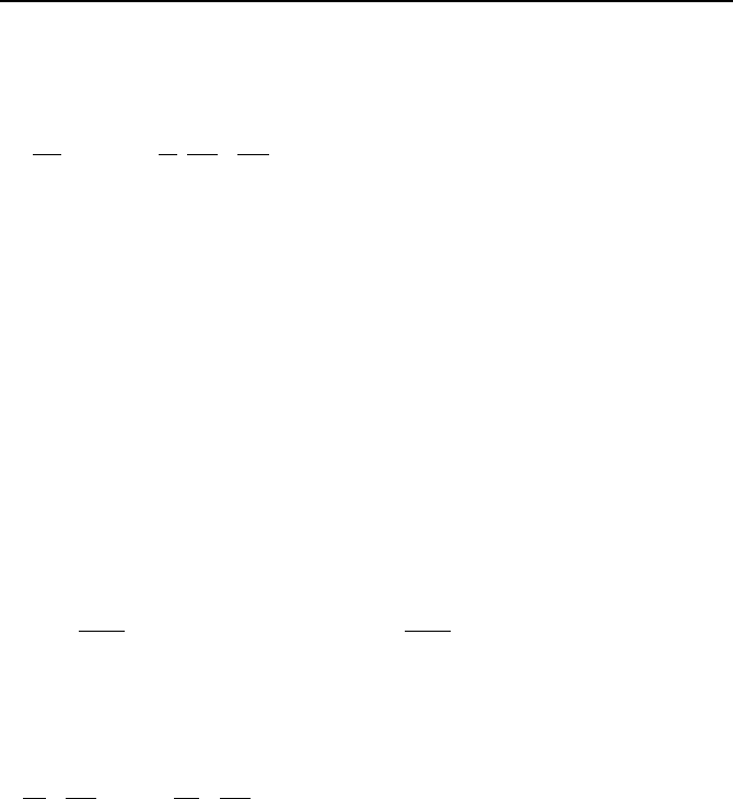
Earlier, as part of fluid kinematics we studied the acceleration of a fluid element in
a flow field. Another aspect of fluid motion is fluid deformation, consisting of
linear and angular deformations (see Figure IIIa.3.5). In linear deformation, the
fluid particle moves about without any distortion. In contrast, there is a change in
the orientation of the fluid element when undergoing an angular deformation.
Fluid rotation is, therefore, a linear deformation. It can be shown (see Prob-
lem 55) that the angular velocity in fluid rotation is given as:
3. Conservation Equations 265
Translation Rotation Linear deformation Angular deformation
x
y
d
β
d
α
l
y
l
x
o
a
b
Figure IIIa.3.5. Types of fluid motion (Fox)
(
)
2/V
K
K
K
×∇=
ω
For definition of curl and positive sign of the product of two vectors see Chap-
ter VIIc. Another related variable is defined as Vorticity, being twice the rotation
vector (i.e.
V
K
K
K
K
×∇==
ωζ
2 ).
Example IIIa.3.15. Find the vorticity of a fluid particle at x = 1 cm, y = 2 cm,
and z = –1 cm in a flow field given as kzjyzyixyV
K
K
GK
22
5.0)(2 ++−= cm/s.
Solution: Using the definition of the curl operator from Chapter VIIc, we find
kxiy
K
K
K
2−=
ζ
s
–1
. At the specified point, the velocity and the vorticity vector are;
kjiV
K
K
G
K
5.024 +−= cm/s and ki
K
K
K
22 −=
ζ
s
–1
, respectively.
Derivation of Bernoulli Equation from Differential Momentum Equation
The Bernoulli equation can be derived from the Euler form of the Navier-Stokes
equations. Recall that the Euler equation is for an inviscid, incompressible, and
constant property fluid with gravity as the only body
force:
1V
VVg P
t
ρ
∂
+⋅∇=−∇
∂
K
KK
KK
K
Also recall that the convective acceleration term is the source of non-linearity in
the conservation equation of momentum. To be able to deal with this troublesome
term, we notice that it can be substituted from the following vectorial identity:
() () ( )
VVVVVV
K
K
K
K
K
K
K
K
K
×∇×−⋅∇=∇⋅
2
1
to get:
()
()
11
2
V
VV V V g P
t
ρ
∂
+∇ ⋅ −×∇× =−∇
∂
K
KKK
KK K K
K
266 IIIa. Fluid Mechanics: Single-Phase Flow Fundamentals
∆Z
θ
Control Volume
∆
s
τ
w
Fi
g
ure IIIa.3.6. One-dimensional flow of fluid in an arbitrar
y
conduit
The third term represents the cross product of the velocity vector and the vorticity
vector, which is now the only troublesome term. This term can be eliminated for
two conditions. The first condition is when we are dealing with irrotational flow.
Because for irrotational flow vorticity is zero hence,
0=×∇ V
KK
. With the third
term eliminated, the above equation can be integrated between point i and point e.
The second condition is when point i and point e are located on a streamline. In
this case, the third term in integration goes to zero. To demonstrate, we multiply
both sides of the equation by an element of length,
rd
K
, which lies on the stream-
line. It can be easily shown that the non-linear term is eliminated, as
(
)
[
]
0=⋅×∇× rdVV
K
K
K
K
, and the rest of the equation after integration becomes:
0
2
2
=
µ
µ
¶
´
¸
¸
¹
·
¨
¨
©
§
+++
µ
¶
´
⋅
∂
∂
e
i
e
i
dP
gdz
dV
ds
t
V
ρ
K
IIIa.3.34
where points i and e are located on a streamline. Equation IIIa.3.34 is the time
dependent form of the Bernoulli equation. For steady and incompressible flow,
this equation reduces to the Bernoulli equation (Equation IIIa.3.33).
Derivation of Bernoulli Equation from the Integral Momentum Equation
We begin by analyzing the one-dimensional steady flow of a fluid in an arbitrary
conduit as shown in Figure IIIa.3.6. The steady state continuity equation results in
d(
ρ
VA) = 0 hence, m
=
ρ
VA = constant. The steady state momentum balance re-
lates the body (weight of the fluid) and surface forces (pressure and viscous
forces) to the momentum flux:
0)/)((sin)()/( =+++ dsdsdVVAgAdsdsDAdsdsdP
hw
ρθρπτ
Dividing through by Ads, we obtain:
gdZDdsVdVdP
hw
ρτρ
++=− )/(4 IIIa.3.35
We may now integrate this equation between points 1 and 2 along the length of
the channel. There are several problems that we must resolve to be able to per-
form the integration. The first problem is flow velocity, which may not be uni-
form at a given location along the conduit. To resolve this problem, we consider
3. Conservation Equations 267
the case of highly turbulent flow so that velocity is approximately uniform over
the flow cross section. The second problem is the fact that the flow cross section
may vary along the conduit. To be able to integrate, let’s only consider the case of
fluid flow in a conduit with a uniform cross section, such as a circular pipe or
tube. The third problem to resolve is the fact that, for compressible fluids, density
changes from point 1 to point 2 along the length of the conduit. This change in
density may be as a result of heating or cooling the flow. To deal with this prob-
lem, we use densities at point 1 (
ρ
1
) and at point 2 (
ρ
2
) to obtain an average den-
sity
ρ
. Since the average specific volume is given as v = v
1
+ v
2
, we substitute
for v = 1/
ρ
to obtain the average density as:
21
111
ρρρ
+=
With these modifications in mind, we now integrate Equation IIIa.3.35 to obtain:
()
12
2
2
12
21
11
ZZgP
A
m
PP
fric
−+∆+
¸
¸
¹
·
¨
¨
©
§
−=−
ρ
ρρ
IIIa.3.36
where the first term in the right side of Equation IIIa.3.36 was obtained by the fol-
lowing substitution:
2
2
21
2
1
2
1
2
2
111
A
m
d
A
m
VdV
¸
¸
¹
·
¨
¨
©
§
−=
µ
¶
´
¸
¸
¹
·
¨
¨
©
§
=
³
ρρρ
ρ
For incompressible flow,
ρ
1
≅
ρ
2
≅
ρ
hence, the first term in the right side of
Equation IIIa.3.36 is practically zero. The second term in the right side of Equa-
tion IIIa.3.36, is the frictional pressure drop, which is discussed in Chapter IIIb.
Application of Equation IIIa.3.36 is discussed in Chapter IIIb (Example IIIb.4.7).
For inviscid flow (
∆P
fric
= 0), Equation IIIa.3.36 reduces to Equation IIIa.3.33, the
Bernoulli equation.
Derivation of the Bernoulli Equation from Euler’s Equation for Streamlines
In Example IIIa.3.10, we derived the Euler’s equation in streamline coordinates
(
sn) as:
0
1
=
∂
∂
+
∂
∂
+
∂
∂
+
∂
∂
s
z
g
s
P
s
V
V
t
V
ρ
IIIa.3.37
To integrate this equation along the streamlines between points 1 and 2, we multi-
ply the above equation by
ds and integrate:
µ
¶
´
=
¸
¸
¹
·
¨
¨
©
§
+++
µ
¶
´
∂
∂
2
1
0
1
gdzdPVdVds
t
V
ρ
IIIa.3.38
268 IIIa. Fluid Mechanics: Single-Phase Flow Fundamentals
or alternatively;
0)()(
1
2
1212
2
1
2
2
2
1
=−+−+
−
+
µ
¶
´
∂
∂
ZZgPP
VV
ds
t
V
ρ
IIIa.3.39
Equation IIIa.3.39 for steady flow reduces to Equation IIIa.3.33 (i.e., the Bernoulli
equation).
One-Dimensional Momentum Equation for Viscous Flow
If we are dealing with viscous flow, the applicable equation should account for
frictional losses. Hence, we can use the modified form of Equation IIIa.3.37 writ-
ten as
0hh
1
2
1
2
1
=
µ
¶
´
¸
¸
¹
·
¨
¨
©
§
+++++
µ
¶
´
∂
∂
sf
gdgdgdZdPVdVds
t
V
ρ
IIIa.3.40
Integrating;
()
0hh
1
2
2
1
12
2
1
2
2
2
1
=
µ
¶
´
»
¼
º
«
¬
ª
++−++
−
+
µ
¶
´
∂
∂
sf
ggZZgdP
VV
ds
t
V
ρ
IIIa.3.41
If the flow is incompressible, then Equation IIIa.3.41 can be integrated to obtain:
0hh)()(
1
2
1212
2
1
2
2
2
1
=++−+−+
−
+
µ
¶
´
∂
∂
sf
ggZZgPP
VV
ds
t
V
ρ
IIIa.3.42
The integral term can be written as:
()
=
µ
¶
´
=
µ
¶
´
∂
∂
2
1
2
1
/
ds
dt
Amd
ds
t
V
ρ
dt
mdI
A
ds
dt
md
ρρ
=
µ
¶
´
2
1
Substituting for the integral term and dividing through by g, Equation IIIa.3.42
becomes:
0hh)()(
1
2
1
1212
2
1
2
2
=++−+−+
−
+
sf
ZZPP
gg
VV
dt
md
I
g
ρρ
IIIa.3.43
where I =
Σ(L/A) is called the geometrical inertia. Note that Equation IIIa.3.43 is
written in terms of heads;
(I/
ρ
g)d m
/dt: Inertia head
(
2
1
2
2
VV − )/(2g): Velocity head
(P
2
− P
1
)/(
ρ
g): Static pressure head
(Z
2
− Z
1
): Elevation head
3. Conservation Equations 269
h
f
: Friction head
h
s
: Shaft head
For steady incompressible flow with h
s
= h
f
= 0, Equation IIIa.3.43 reduces to the
Bernoulli equation. If we multiply the terms of Equation IIIa.3.43 by
ρ
g, each
term can be expressed as a differential pressure term:
∆P
Inertia
+ ∆P
vel-acc
+ ∆P
static
+ ∆P
gravity
+ ∆P
friction
+ ∆P
shaft
= 0 IIIa.3.44
If the shaft work is due only to the pump in the flow path, Equation IIIa.3.44 can
be written as
∆P
pump
– (∆P
Inertia
+ ∆P
vel-acc
+ ∆P
static
+ ∆P
gravity
+ ∆P
friction
) = 0 IIIa.3.45
or alternatively as
)()(
fricacclgravstatpump
PPPPP
dt
md
A
L
∆+∆+∆+∆−∆=
¦
IIIa.3.45
Note that the differential pressure shown by
∆P is generally defined as ∆P = P
2
–
P
1
. In the case of the differential pressure due to friction, ∆P is always a negative
number. To avoid the use of a minus sign, we define
∆P
friction
as ∆P
friction
= P
1
– P
2
throughout this book.
Applicability of the Bernoulli Equation
The Bernoulli equation is the most widely known equation in the field of hydrau-
lics due to its simplicity, which came at a high price including the following re-
strictions:
− flow must be at steady state conditions
− there should not be any shaft work, viscous work, or any other work
− flow must be inviscid, incompressible, with uniform properties
− flow must be either irrotational or the end points i and e must lie on a stream-
line.
These are stringent conditions to meet. The lack of frictional effects implies
that the Bernoulli equation cannot be applied where flow encounters obstacles that
cause unrecoverable pressure loss to the flow. The no shaft work requirement pre-
cludes using the Bernoulli equation across a pump, compressor, or a turbine, for
example. The uniform properties requirement precludes applying the Bernoulli
equation to situations where density at the exit is substantially different than
density at the inlet. Hence, the Bernoulli equation cannot be applied across a cool-
ing or heating coil over which a gas is flowing.
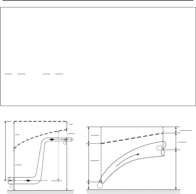
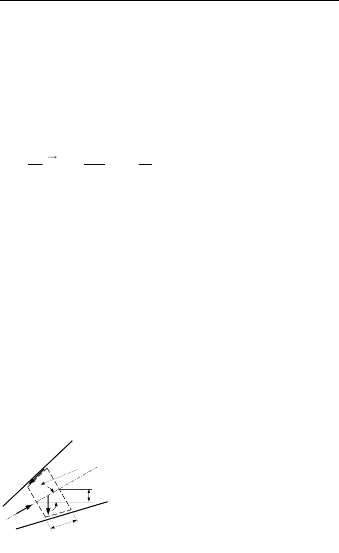
These restrictions require careful assessment of a problem before a solution
based on the Bernoulli equation is embarked upon. For example, a hydraulic jump
(Figure IIIa.3.7) is an irreversible process (associated with head loss) which oc-
curs at certain conditions for a liquid flowing at high speed in a wide, horizontal
open channel. While it is tempting to apply the Bernoulli equation at end points
before and after the jump, the associated irreversibility and the fact that we cannot
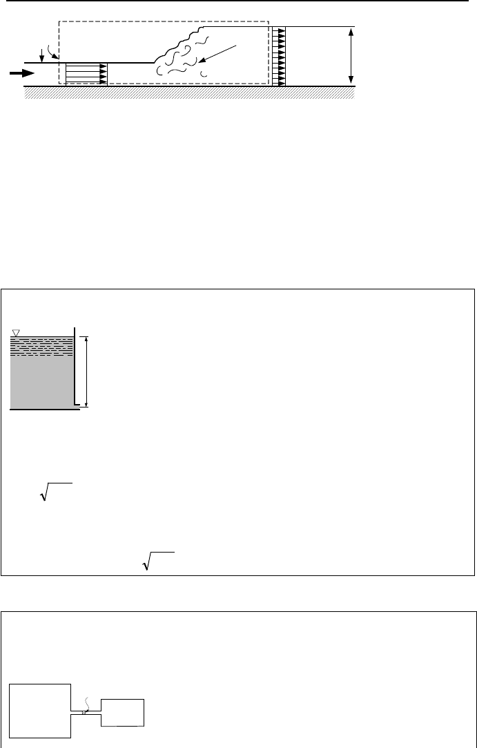
270 IIIa. Fluid Mechanics: Single-Phase Flow Fundamentals
V
1
V
2
z
1
z
2
1
2
Control
Volume
V
.
Eddies
Figure IIIa.3.7. Hydraulic jump in a rectangular channel
trace a streamline between the end points, precludes doing so. Regarding the in-
compressibility requirement of the flow, we can apply the Bernoulli equation to a
compressible flow as long as flow velocity remains about 30% of the speed of
sound in the fluid.
Next, we shall solve several examples to which the Bernoulli equation can be
applied. It is important to note that for cases that the Bernoulli equation does not
apply, we should use the applicable momentum equation such as Equa-
tion IIIa.3.31 or Equation IIIa.3.43.
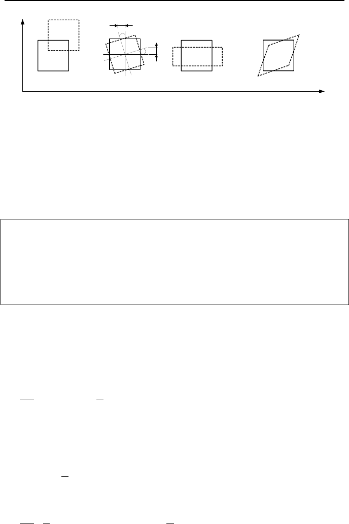
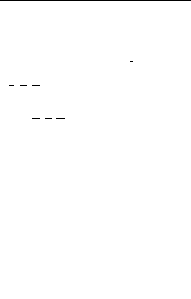
Example IIIa.3.16. Water flows through a small opening located at depth h in a
large reservoir. Find water velocity.
h
1
2
Solution: Applying the Bernoulli equation between points 1 and 2, noting equal
pressures (P
1
= P
2
), and the fact that V
1
≈
0 compared with V
2
, we can solve for
V
2
to obtain:
h2
2
gV =
IIIa.3.46
The mass flow rate is, therefore, found as
22
VAm
ρ
=
. In Chapter IIIb we shall
see that flow rate is reduced due to a discharge coefficient. The actual mass flow
rate is then
h2
2
gACm
d
ρ
=
.
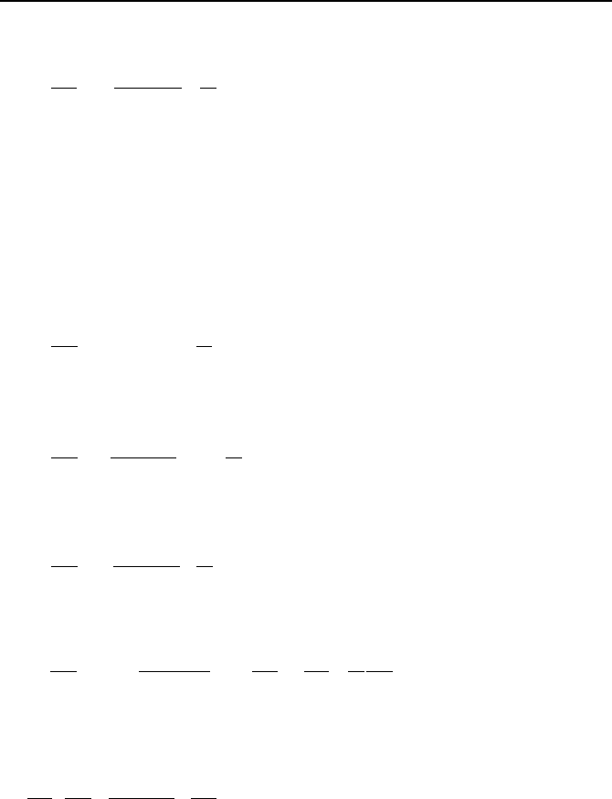
Example IIIa.3.17. A horizontal and frictionless flow path connects two reser-
voirs. The cross sectional area of reservoir 1 is much larger than that of the flow
path. If pressure is maintained in both reservoirs, find the mass flux in the flow
path.
P
1
P
2
A
ρ
3. Conservation Equations 271
Solution: Applying the Bernoulli equation between points 1 and 2, we obtain:
2
2
2
21
V
PP
ρ
+=
Solving for V
2
, we find,
()
ρ
/2
212
PPV −= . Multiplying both sides by density,
yields:
()
212
2 PPVG −==
ρρ
IIIa.3.47
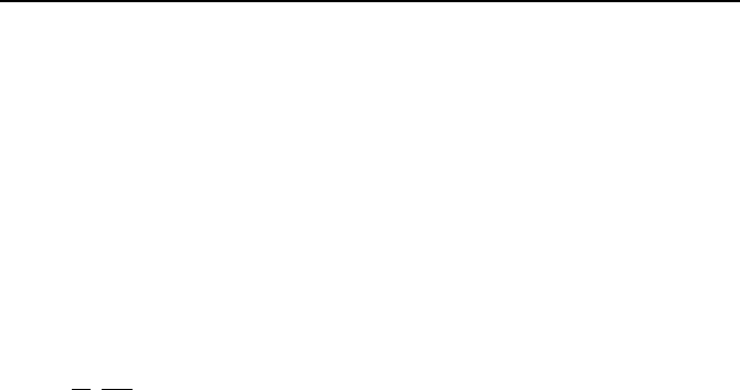
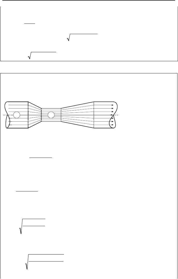
Example IIIa.3.18. The device shown in the figure is known as a venturi. In this
specific venturi, the differential pressure between locations 1 and 2 is 5 psi and the
diameter ratio is D
2
/D
1
= 0.35. If D
2
= 8 inches, find the air flow rate through the
frictionless venturi.
21
Solution: Applying the Bernoulli equation between points 1 and 2, noting equal
elevations (Z
1
= Z
2
), and solving for V
2
, we get:
]
)(2
[
21
2
1
2
2
ρ
PP
VV
−
=−
To get rid of velocity at point 1, we use the continuity equation; V
1
A
1
= V
2
A
2
so
that V
1
= V
2
A
2
/A
1
. If we now substitute for V
1
in terms of V
2
and use A
2
/A
1
=
(D
2
/D
1
)
2
=
β
2
we obtain:
)1(
)(2
4
21
2
2
βρ
−
−
=
PP
V
Substituting for =V
V
2
A
2
, we find volumetric flow rate in terms of pressure drop,
throat flow area and
β
:
)1(
)(2
V
4
21
2
βρ
−
−
=
PP
A
IIIa.3.48
To calculate the volumetric flow rate from Equation IIIa.3.48, we have A
2
=
3.14(8/12)
2
/4 = 0.349 ft
2
. Using density of air at standard condition, we find:
/minft2900
)35.01(076.0
)1445(2
349.0V
3
4
≈
−
×
=
In this problem we demonstrated the usefulness of the Bernoulli equation in de-