Maier S.A. Plasmonics: Fundamentals and Applications. Майер С.А. Плазмоника: Теория и приложения
Подождите немного. Документ загружается.

104 Electromagnetic Surface Modes at Low Frequencies
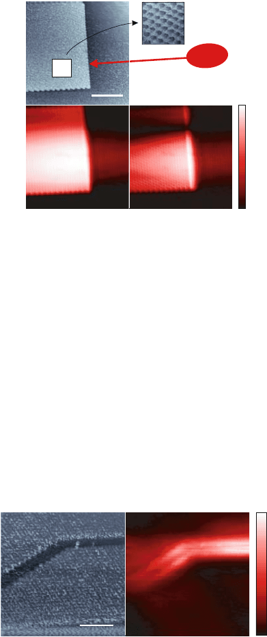
the dependence of the periodicity in intensity contrast in the obtained images
on the illumination wavelength. Representative images are shown in Fig. 6.14.
In this study, propagation lengths 30 μm ≤ L ≤ 200 μm were achieved, vary-
ing with the level of confinement. It has further recently been shown that the
propagation can be tailored by small changes in surface topography [Ocelic
and Hillenbrand, 2004].
After these promising studies, one can expect that concepts borrowed from
plasmonics at visible frequencies can and will be successfully applied in the
mid-infrared using phonon excitations.
PART II
APPLICATIONS
Introduction
Armed with a sufficient background knowledge, this second part presents
five prominent research areas in plasmonics. We start with an overview of
different efforts to exert control over the propagation of surface plasmon po-
laritons. The promise behind plasmon waveguides is a new, highly integrated
photonic infrastructure that might close the size gap with electronic devices.
Control over the transmission of light through sub-wavelength apertures via
plasmon excitations is an equally exciting area, which has spurred a tremen-
dous amount of research ever since the initial description in 1998 of enhanced
transmission of light encountered in aperture arrays. The next two chapters
describe how highly localized fields around metallic nanostructures can lead
to dramatic enhancements of the emission of molecules placed into these hot
spots, and different methods for spectroscopy of localized modes. These chap-
ters also include a cursory discussion of biological sensing and labeling using
surface plasmons. We close with a short introduction into the field of metallic
metamaterials, artificial constructs with sub-wavelength structure that exhibit
novel optical phenomena such as artificial magnetism or indeed a negative re-
fractive index.
Chapter 7
PLASMON WAVEGUIDES
Having described the basics of surface plasmon polaritons in chapter 2, we
continue the discussion by providing a number of examples of control over
their propagation in the context of waveguiding. Here, the trade-off between
confinement and loss demands a judicious choice of geometry, depending on
the length scale over which energy is to be transferred. For example, thin
metallic slabs embedded in a homogeneous dielectric medium can guide SPPs
over distances of many centimeters at near-infrared frequencies, but the associ-
ated fields are only weakly confined in the perpendicular direction. In the other
extreme, metal nanowire or nanoparticle waveguides exhibit a transverse mode
confinement below the diffraction limit in the surrounding host, but with large
attenuation losses, leading to propagation lengths on the order of micrometers
or below.
Routing of SPPs on planar interfaces can be achieved by locally modifying
their dispersion via surface modulations, which will be described in the first
two sections of this chapter. We then focus on studies of lateral confinement
in metal stripe and wire waveguides, including focusing of SPPs in conical
structures. The inverse structure to metal stripes, namely metal/insulator/metal
heterostructures, also show high promise for waveguiding with good confine-
ment and acceptable propagation length, especially in V-groove geometries.
Towards the end of this chapter, we show that localized plasmon excitations
in metal nanoparticles can also be used as waveguiding modalities, since en-
ergy is transferred via near-field coupling between adjacent particles in linear
chains. The chapter closes with a description of emerging efforts to combat
attenuation via optical gain media as waveguide hosts.
110 Plasmon Waveguides
7.1 Planar Elements for Surface Plasmon Polariton
Propagation
The propagation direction of SPPs at the interface of a metal film and a
dielectric superstrate (air or dielectric) can be controlled via scattering of the
propagating, two-dimensional waves at locally created defects in the otherwise
planar film. The scatterers can be introduced in the form of surface undula-
tions such as nanoscale particle-like structures, or by the milling of holes into
the film. Their controlled positioning enables the generation of functional el-
ements such as Bragg mirrors for reflecting SPPs [Ditlbacher et al., 2002b],
or focusing elements for increasing lateral confinement [Yin et al., 2005, Liu
et al., 2005]. This way, a planar two-dimensional photonic infrastructure for
the guiding of SPPs can be created.
A simple and compelling example of control over SPP propagation via
scattering from height modulations was demonstrated by Ditlbacher and co-
workers [Ditlbacher et al., 2002b]. Using electron beam lithography and chem-
ical vapor deposition, silica nanostructures such as particles and wires of 70 nm
height were deposited on a silica substrate, and the height-modulated film sub-
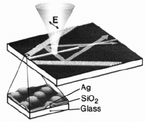
sequently coated with a 70 nm thick silver film (Figure 7.1). In order to excite
SPPs, the method of phase-matching via scattering of the excitation beam (in
this case a Ti:sapphire laser beam with λ
0
= 750 nm) at a nanowire-shaped de-
fect was used (see chapter 3). The SPP propagation pathway was monitored by
coating the film with a polymer layer containing fluorescent dyes (see chapter
4). This also enabled an estimate of the 1/e propagation distance of the SPPs
at the silver/polymer film, here of the order of 10 μm.
Figure 7.1. Routing of SPPs on a planar silver film using surface modulations. A laser beam
focused on a nanowire or nanoparticle defect for phase-matching acts as a local source for SPPs.
The micrograph shows a Bragg reflector consisting of lines of regularly spaced, particle-like
undulations (Fig. 7.2). Reprinted with permission from [Ditlbacher et al., 2002b]. Copyright
2002, American Institute of Physics.
Planar Elements for Surface Plasmon Polariton Propagation 111
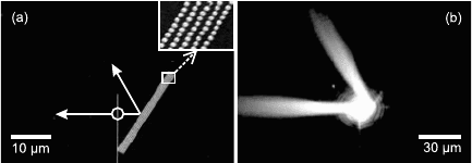
Figure 7.2. (a) SEM image of a SPP Bragg reflector consisting of ordered particle arrays
on a metal film substrate. (b) SPP propagation imaged via monitoring of the emission of a
fluorescent superstrate. Reprinted with permission from [Ditlbacher et al., 2002b]. Copyright
2002, American Institute of Physics.
Fig. 7.2 shows a Bragg reflector based on this principle, consisting of par-
allel lines of particles with diameter 140 nm. An interline spacing of 350 nm
(Fig. 7.2a) fulfilled the Bragg condition for SPPs impinging at a 60
◦
angle on
the array and thus lead to the specular reflection of the SPP wave (fluorescent
image in Fig. 7.2b). In this case, the reflection coefficient of a Bragg mirror
consisting of 5 lines was estimated to be 90%, with the remaining fraction
being scattered out of the plane into radiation. This proof-of-principle study
suggests that planar passive optical elements for the routing of SPP propaga-
tion can be fabricated in an easy manner. We will show in the next section
that the lateral extent of SPPs can be controlled by extending the Bragg mirror
concept to create surface plasmon photonic cyrstals exhibiting band gaps for
propagation in desired frequency regions.
Another approach for controlling SPP propagation at a single metal inter-
face is the spatial modification of the SPP dispersion and thus phase veloc-
ity via dielectric nanostructures deposited on top of the film [Hohenau et al.,
2005b], by analogy to the conventional routing of free-space beams with di-
electric components such as lenses. Figure 7.3 shows the calculated dispersion
relations of SPPs in a glass/gold/superstrate multilayer system for both the s
modes (magnetic fields on the two metal interfaces in phase) and the a modes
(magnetic fields at the two metal interfaces out of phase) for varying dielectric
constants ε
3
of the superstrate. It is evident that an increase in ε
3
leads to an
increase in SPP wave vector, as discussed in chapter 2. This implies that the
phase velocity of the propagating waves can be locally decreased by introduc-
ing dielectric structures on top of the metal film. By adjusting the geometric
shape of the dielectric perturbations and thus the regions of reduced phase ve-
locity, it is therefore possible to fabricate optical components such as lenses
and waveguides for SPP propagation, albeit with increased attenuation due to
the closer confinement of the mode to the metal surface.
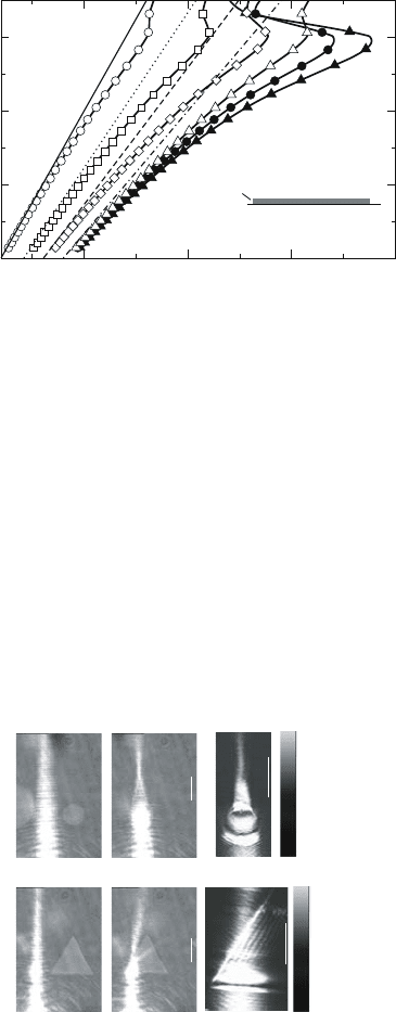
Figure 7.4 demonstrates that via this concept, the focusing (top row) and
refraction/reflection (bottom row) of SPPs can be achieved using cylindrical- or
112 Plasmon Waveguides
10
15
20
25
k
SPP
(µm
-1
)
6
8
10
12
k
light,vacuum
(µm
-1
)
ε
1
substrate
=2.25
ε
3
ε
2
50nm Au
superstrate
Figure 7.3. Calculated SPP dispersion relations for a glass/gold/superstrate three-layer system
for both the s mode (open symbols) and the a mode (filled symbols). Increasing the dielectric
constant ε
3
of the superstrate from ε
3
= 1 (circles) to ε
3
= 2.25 (triangles) leads to an increase
in propagation constant and thus a decrease in phase velocity of the SPP. For ε
1
= ε
3
,thesetwo
modes would evolve into the symmetric (s) or asymmetric (a) mode. Reprinted with permission
from [Hohenau et al., 2005b]. Copyright 2005, Optical Society of America.
triangular-shaped particles, by direct analogy to the three-dimensional optical
elements of conventional free-space optics.
In their study, Hohenau and co-workers excited the SPPs with an immersion
oil objective and observed SPP propagation via monitoring of leakage radia-
tion (Fig. 7.4 a, b, d, e) and near-field optical microscopy (Fig. 7.4 c, f). The
10µm
10µm 10µm
10µm
1
0
arb. u.
1
0
arb. u.
(a)
(b)
(c)
(d)
(e)
(f)
Figure 7.4. Focusing (top row) or reflection and refraction (bottom row) of SPPs via a cylin-
drical or triangular 40 nm thick dielectric structure deposited on top of a gold film. Images of
the leakage radiation (a, b, d, e) and of the optical near field (e, f) clearly show the modification
of SPP propagation for SPPs impinging on the dielectric structures (b, c, e, f). Reprinted with
permission from [Hohenau et al., 2005b]. Copyright 2005, Optical Society of America.
Planar Elements for Surface Plasmon Polariton Propagation 113
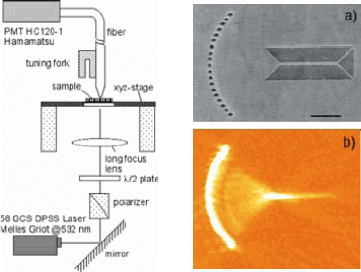
Figure 7.5. Experimental setup of the excitation and near-field imaging for SPP focusing on
a holey metal film (left). (a) SEM and (b) near-field optical image of the nanohole focusing
array which couples the launched SPPs into a 250 nm wide silver stripe guide. Reprinted with
permission from [Yin et al., 2005]. Copyright 2005, American Chemical Society.
same concept should also allow for the creation of the SPP analogue of dielec-
tric waveguides via the creation of one-dimensional regions of reduced phase
velocity, which was experimentally confirmed using one-dimensional polymer
nanostructures on a gold layer [Smolyaninov et al., 2005].
We will conclude this section by presenting two recent studies of focusing
using holes and grooves directly milled into the metallic film sustaining the
SPPs. Figure 7.5 shows how constructive interference between SPPs launched
locally using illumination of nineteen 200 nm holes arranged on a quarter circle
of radius 5 μm in a 50 nm silver film gives rise to a tight focus spot in the center
of the circle [Yin et al., 2005]. As an application, Yin et al. used their focusing
element for coupling SPPs into a 250 nm wide stripe waveguide (see images a
and b in Fig. 7.5).
Excitation and subsequent focusing of SPPs can also be achieved using cir-
cular or elliptical sub-wavelength slits milled into a metallic film [Liu et al.,
2005]. In this case, the edge of the circular slit acts as a point source for
SPPs upon illumination of the slit structure, in regions where the exciting elec-
tric field is polarized perpendicular to the slit, and the generated SPPs will be
launched and focused towards the center of the circle. The non-resonant nature
of this process makes this scheme suitable for focusing SPPs excited at dif-
ferent frequencies throughout the visible spectrum, albeit with low efficiency.
Fig. 7.6a shows SPP focusing using a circular slit structure of radius 14 μmand
width 280 nm, milled into a 150 nm thick silver film. The near-field pattern for
excitation with linearly polarized light was recorded using near-field optical
microscopy. As apparent, only two opposite regions of the circle, where the
electric field is polarized perpendicular to the slit, act as SPP sources. Illumi-
nation with unpolarized light however leads to SPP generation throughout the

114 Plasmon Waveguides
Figure 7.6. Generation and focusing of SPPs via illumination of circular or elliptic slits milled
into a metallic film. The SPP intensity is monitored via near-field microscopy (a,c) or the
exposure of a photoresist superstrate (b, d). Reprinted with permission from [Liu et al., 2005]
Copyright 2005, American Chemical Society.
circumference, shown in Fig. 7.6 for an ellipse of axes 4 μmand2μm cut into
a 70 nm thick aluminum film. In this case, the near-field pattern was recorded
via the exposure of a photoresist layer.
It can be anticipated that the combination of functional elements such as the
ones discussed in this section will enable planar photonic circuits working at
optical or near-infrared frequencies, with propagation distances below 100 μm.
7.2 Surface Plasmon Polariton Band Gap Structures
The concept of constructively reflecting SPPs on a metal film via Bragg re-
flectors created using periodically arranged metallic nanoparticles presented in
Figs. 7.1 and 7.2 can be extended to the creation of band gaps for SPP prop-
agation using regular metal nanoparticle lattices deposited on a metal film.
Bozhevolnyi and co-workers demonstrated that a triangular lattice of gold dots
on a thin gold film establishes a band gap for SPP propagation [Bozhevolnyi
et al., 2001]. An example of such a structure is shown in Fig. 7.7 for a tri-
angular lattice of gold scatters fabricated on a 40 nm thin gold film. In this
case, the lattice constant was chosen to be 900 nm, and the individual scatters
are 378 nm wide and 100 nm high, resulting in the formation of a band gap in
the telecommunication window (wavelengths around λ = 1.5 μm) [Marquart
et al., 2005]. The penetration of SPPs (excited via prism coupling on the flat
parts of the film) incident on this structure can be monitored using near-field
optical microscopy, and examples of near-field images obtained at two differ-
ent wavelengths are shown in panels (b) and (c). This way, the band gap for
SPP propagation can be determined for a given direction of the incident SPPs
by determining the penetration distance of the surface waves into the lattice
structure.
Surface Plasmon Polariton Band Gap Structures 115
100 %
50 %
24 %
11 %
4%
0%
,
c
,
,
a
,
b
10 m
Figure 7.7. Topography (a) and near-field optical images (b,c) of a 35×35 μm
2
SPP band gap
structure consisting of a 900 nm triangular lattice of 378 nm wide and 100 nm high gold dots on
a 40 nm thick gold film. SPPs excited via prism coupling of radiation of wavelength 1550 nm
(b) or 1600 nm (c) propagate from the right into the lattice structure in the K direction, and
are strongly attenuated if their frequency is inside the band gap (c). Reprinted with permission
from [Marquart et al., 2005]. Copyright 2005, Optical Society of America.
An application of this concept in waveguiding is obvious: by creating mi-
cron-wide line defects where the triangular lattice of scatters is locally re-
moved, SPPs can be laterally confined in channel waveguides, akin to well
established concepts in planar dielectric photonic crystals. Figure 7.8 shows a
near-field optical image of SPPs excited at λ
0
= 1550 nm via prism coupling,
guided within a channel defect waveguide in a triangular lattice of gold dots
separated by a period 950 nm. Note that in this case parts of the guided SPPs
ab
10 m
100 %
80 %
60 %
40 %
20 %
0%
Figure 7.8. Topographical (a) and near-field optical (b) image of a channel defect waveguide
in a triangular lattice of period 950 nm consisting of 438 nm wide and 80 nm high gold scatters
on an gold film. A SPP excited at λ
0
= 1515 nm incident from the right propagates through
the channel. Reprinted with permission from [Marquart et al., 2005]. Copyright 2005, Optical
Society of America.