Kutz M. Handbook of materials selection
Подождите немного. Документ загружается.


1066 COMPOSITES FABRICATION PROCESSES
Either ambient temperature or elevated temperature cure resins may be used.
The characteristics required of the resin depend on the chosen method of infil-
tration. The resin may be preimpregnated into the reinforcement either before,
during, or after preform manufacture. Alternatively the resin may be placed in
the mold with the preform as a liquid or sometimes as a film or sheet. A further
possibility is that the resin is injected into the closed mold; this is resin transfer
molding (RTM) and is discussed in a later section. Any of the common ther-
mosetting resins may be used; UPE and vinyl-ester systems are the most com-
mon. To minimize the molding time, a fast curing system is desirable, subject
to full infiltration and control of the exotherm during cure.
Press molding is widely used with precompounded reinforcements such as
prepreg, sheet and bulk molding compounds (SMC, BMC), and also with ther-
moplastic matrix systems, e.g., glass-mat/thermoplastic (GMT), these are dis-
cussed in later sections.
4.3 Ambient Cure Press Molding
In this version of the process low pressures and unheated tooling is used with
a very fast curing resin formulation. A typical sequence of operations is that the
preform is loaded into the open mold, a carefully metered quantity of the resin,
which must be of low viscosity and have been just mixed with the initiator, is
poured or sprayed into the mold. The mold is then closed and the consolidating
pressure applied. This forces the liquid resin to completely infiltrate the preform.
Vents are often provided to allow a little excess resin to escape, but the process
depends on the hydrostatic pressure generated in the resin to effect the infiltra-
tion. The mold remains closed and under pressure until the resin is sufficiently
cured. This may take anywhere from 2 to 20 min depending of size and com-
plexity of the molding. The fast curing resin generates a considerable exotherm,
so that the molding is heated, often to more than 100
⬚C, during the cure process.
When the cure is judged to be adequate, the press is opened and the (hot) part
is removed. The next preform may then be inserted and the process repeated.
The attraction of this process is that the capital investment of press and tooling
is relatively low and the production rate quite fast. Simple composite tooling is
adequate for short runs. Surface finish may be enhanced by using a quick gelling
sprayed gel coat. The process is not generally suitable for large moldings, e.g.,
⬎2m
2
projected area, and control of dimensions and porosity is relatively poor.
It is very suitable for moderate runs of commodity items where high mechanical
performance is not a requirement.
4.4 Elevated Temperature Cure Press Molding
In this case metal tooling incorporating internal heaters must be used and, gen-
erally, more substantial presses and higher consolidating pressures are used. The
cure temperatures are typically 80–160
⬚C for UPE and vinyl ester (VE) systems
and up to 250
⬚C for epoxy and some high-temperature resins. The general pro-
cedure is similar to that described above for ambient cure. However, there is
much more flexibility as a fast curing (at ambient temperature) resin is not
necessary. Resins are formulated to cure in 2–20 min at the relevant cure tem-
peratures. They then have reasonably long pot lives at shop temperature. Pre-
forms are again preferred and the resin applied as liquid or film. The press is
5 AUTOCLAVE PROCESSING OF PREPREG 1067
Vacuum manifold
Nitrogen pressure line
Temperature & cure
monitoring connections
Opening door
Gas circulation fan
Heaters
Laminates on tooling
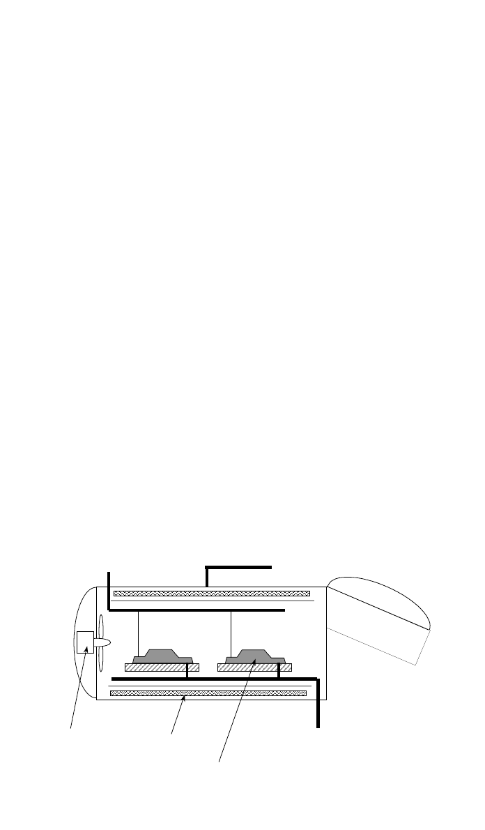
Fig. 16 Industrial autoclaves vary in size from less than 1 m diameter to more than 4 m, and
in some cases more than 10 m in length. They are substantial pressure vessels. The interior is
pressurized with nitrogen and may be heated, typically up to 250⬚C. A vacuum manifold and
monitoring connections are provided to attach to the individual tools.
closed, and, as the resin is heated, it first becomes less viscous so that infiltration
is accelerated. The application of pressure is often programmed during this pe-
riod, typically a few minutes. When the charge has been heated and the full
pressure applied, the resin is allowed to cure. Again, consideration must be given
to dissipation of the heat generated during cure, but generally conduction to the
metal tooling is quite effective in preventing hot spots and burning. Surface
finish may, again, be enhanced by use of a gel coat, and a further option is to
slightly open the mold after gelation of the main charge and to inject a further
quantity of pigmented resin between the workpiece and the mold wall, sufficient
to form a surface layer 0.5–1.0 mm thick. The pressure is then reapplied while
this injected gel coat is cured. At the completion of the cure, the press is opened
and the hot part is ejected. Average times for the complete cycle are 10–20 min.
This is much faster than can be achieved with contact molding, and there is the
additional benefit of closer tolerances, better surface finish, and better quality
control. The negative aspects are higher investment in tooling and equipment
and size limited to the sizes of the available presses, e.g., 2
⫻ 1 m plan form.
5 AUTOCLAVE PROCESSING OF PREPREG
5.1 Autoclave
An autoclave, shown schematically in Fig. 16, is a pressure vessel capable of
being internally pressurized with a gas, which can also be independently heated.
This is in contrast to medical autoclaves, which are usually steam operated.
Modern industrial autoclaves are often very large, commonly up to 3 m internal
diameter and 4–6 m in length. They are pressurized with nitrogen gas typically
to pressures of up to 5 bars. The use of nitrogen, rather than air, avoids any
chance of combustion of hot resin or other flammable materials. The contained
gas is mechanically circulated and may be heated to temperatures of up to 400
⬚C,
although
⬇200⬚C is a more common upper limit. There are sometimes also

1068 COMPOSITES FABRICATION PROCESSES
means for cooling the interior. The autoclave with its associated pressurization,
heating and control equipment constitutes a considerable capital investment, typ-
ically in excess of $1 million. This has a significant influence on the cost of
autoclave processed parts. It also occupies a lot of factory space. For these
reasons autoclave processing is mainly used for the manufacture of premium
products in high-performance composites.
5.2 Prepreg
Prepreg is the common name for preimpregnated warp sheet: It was briefly
described in Section 1.2. It consists of a uniaxial array of fiber tows or roving,
formed by butting up a large number of individual tow ends (i.e., fiber from
many spools). The web thus formed may be from 300 mm (tape) to 2000 mm
or more, (broadgoods) wide. It is supported on a carrier film, usually silicone-
treated kraft paper, which has been precoated with a layer of resin. A second
layer of film, also coated in resin, is applied to form a sandwich, which is passed
between a number of heated rolls and then, often, through chilled rolls. This
thoroughly impregnates the fiber web and produces a uniform material. The
objective is to incorporate exactly the correct proportion of resin into the prepreg,
e.g., to form a composite with V
ƒ
⫽ 0.6. Sometimes a small excess of resin is
incorporated so that some may be bled off during cure, but modern practice is
not to bleed (see subsequent discussion) but to use so-called net resin materials.
Standard prepreg is manufactured to be 0.125 mm (
⬇10 mils) thick after proc-
essing. Alternative thinner prepreg is sometimes available, mainly for space ap-
plications and a woven form with a thickness of 0.25 mm per ply is becoming
very popular. Prepregs are manufactured from several grades of carbon fiber,
aramid, E-glass, S2-glass, silica (‘‘quartz’’), and some ceramic fibers. Carbon
and aramid are the most widely used. The resin used in prepreg is formulated
to be pasty at shop temperature with a controlled degree of tack (stickiness).
This allows the sheets to be accurately tailored and then placed, by hand or
machine. Too much tack renders it very difficult to handle (it sticks to every-
thing!). Too little tack makes it more difficult to locate on the tool. The prepreg
is cured by heating, and pressure is used to effect consolidation (see Section
2.2). The prepreg is supplied in continuous rolls, typically 600–1000 mm wide
and up to 100 m long. It is usually necessary that the prepreg be stored in a
cold room (
⬍⫺15⬚C) to maximize storage life.
5.3 Tooling
The most common form of tooling is to use single-sided molds with vacuum
bag consolidation. The tools are usually made from composites, with low-
temperature carbon fiber/epoxy being very popular. These tools are relatively
cheap, robust, and have thermal expansion characteristics that match that of
carbon fiber composites. Since the process is very widely used in the aerospace
industry, where one side of the molding will be the aerodynamic surface, it is
common practice to define this shape at the mold surface. Features such as
stiffeners and ribs are then built up on the inside surface of the molding using
auxiliary mold fixtures. These can become very complex but allow for the man-
ufacture of large intricate moldings, which confer the benefits of parts consoli-
dation.

5 AUTOCLAVE PROCESSING OF PREPREG 1069
5.4 Cutting the Prepreg
Prepreg may be hand or machine cut. The latter is adopted for all but the smallest
operations. The prepreg rolls must first be withdrawn from cold storage and
allowed to equilibrate to shop temperature. This may take up to 24 h. The roll
must not be removed from its protective bag or unrolled while it is cold, oth-
erwise moisture may condense from the atmosphere onto the cold prepreg. This
would lead to water absorption and processing problems, e.g., porosity. Cutting
should be carried out in a clean room with temperature and humidity controlled
[20
⬚C and 50% relative humidity (RH) is common]. For hand cutting shears, a
Stanley knife, or a cutting wheel may be used. It is usual to make templates for
each ply from card, plastic, or sheet metal to provide a cutting guide. Each
template must also indicate the fiber orientation (e.g., 0
⬚,90⬚, Ⳳ45⬚) so that the
template may be correctly positioned on the roll of prepreg. When the width of
the part exceeds the width of the prepreg, it may be necessary to cut several
pieces to make up a single ply. Many moldings are of varying thickness. This
involves ply drops, which are preferably located toward the center thickness so
that there are no steps on the outside surfaces. It will be apparent that the
logistics of laying up a complex laminate of, say, 48 plies, with a specified
configuration, (e.g., the quasi-isotropic [0
⬚,90⬚, Ⳳ45⬚]s), will be quite complex.
Each ply will require a drawing, part number, and template. The plies must then
be cut from the roll of prepreg, with due regard to minimizing wastage; each
ply must be identified and then stacked to form a kit of plies in the correct order
for the lay-up operation. If necessary positional index marks must be placed on
the cover film of each ply to facilitate precise positioning. These are the argu-
ments for using an automated cutting system.
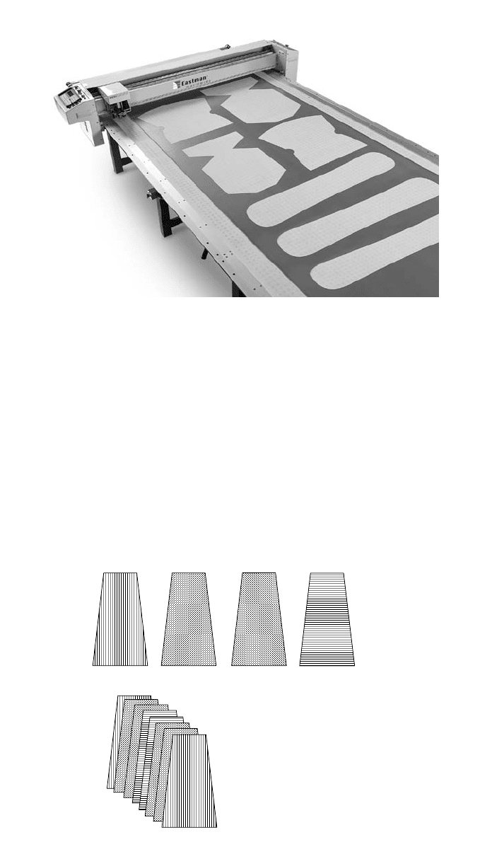
The automatic prepreg cutter consists of a flat bed, typically 2 m wide by 10
m long. The prepreg sheets are unrolled along the bed, butting two or more
together if a wider strip is required and, sometimes, more than one layer. They
are retained in place by suction from under the bed. The cutter head is mounted
on a gantry that moves along the bed in the length direction and may also
traverse in the width and vertical directions. The cutting method may be a re-
ciprocating knife, ultrasonic knife, or water jet. The cutting operation is con-
trolled by a computer that is linked to the CAD system. Thus, each ply is defined
in the software, so neither drawings or templates are required. The software also
incorporates a nesting program that adjusts the cutting sequence to minimize
waste. The software and the machines have been developed from those used in
the garment industry. A small automatic prepreg cutter is shown in Fig. 17. The
cutting operation is initiated and the cutter automatically cuts all the plies defined
on the bed. There is also a printing head that numbers each piece and can print
index marks that are used to facilitate precise lay-up. At the end of the run the
cut plies are gathered and collated, either by hand or by a robotic device that
automatically collects and collates the plies into kits ready for lay-up. Although
the cost of such equipment is high, the benefits in terms of precise cutting, speed,
elimination of hand operations, waste minimization, and improved quality as-
surance are very considerable.
5.5 Hand Lay-up
The tool is prepared and a release agent and/or release film applied across the
molding surfaces. The prepreg kit is delivered to the lay-up location. At this
1070 COMPOSITES FABRICATION PROCESSES
Fig. 17 View of a small automatic prepreg cutting machine. This shows how the plies have
been positioned to minimize wastage. (Photograph by courtesy of the Eastman Machine Co.,
Rochester, NY, Model M9000)
0°
+45°
-45°
90°
Balanced, symmetric,
Quasi-isotropic [0, ± 45,90]
s
laminate formed from 8 prepreg plies
Fig. 18 Illustration of the necessary prepreg ply shapes showing fiber orientations
for laying up a quasi-isotropic laminate.
stage each piece of prepreg is still protected by the plastic or paper film on each
side. The pieces are taken in the correct sequence, the protective film removed
from the mold-face side, and the piece carefully positioned on the tool. Once
its correct location is confirmed, It may then be partly consolidated by use of
hand, brush, or roller. Special care is taken to avoid any wrinkling or pockets
of entrapped air. (The tack allows the ply to be repositioned, if necessary, before
consolidation but not once it has been pressed down.) The outer protective film
may then be removed and the next ply positioned. A typical lay-up sequence is
depicted in Fig. 18. It is usually necessary to further consolidate, or debulk, after
5 AUTOCLAVE PROCESSING OF PREPREG 1071
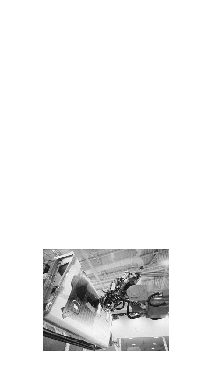
Fig. 19 Large tape laying machine. Both the tape laying head and the tooling are manipulated
to form a large aircraft fuselage component. (Photograph of the Viper tape layer
courtesy of Cincinnati Machine Co., OH)
every 12, or so, plies have been laid. This is done by placing a vacuum bag over
the mold, evacuating and usually warming to 50–70
⬚C for a period of the order
of 60 min, using an oven or radiant heaters. This softens the resin and allows
the pack to consolidate under the pressure exerted across the bag. The next set
of plies may then be placed until the lay-up is complete.
In the case of smaller moldings the prepreg pieces may be handled quite
easily and positioned by eye. If larger pieces,
⬎2 m, are to be placed, some
form of mechanical assistance may be required. Manipulators with suction pads,
which operate on the back cover film, are convenient. For precision placement
index marks must be printed on the back-cover film and a computer-controlled
laser projector, set above the lay-up location, used to project reference spots, a
red spot, or cross onto the back of the laminate. Each ply is lined up with these
reference spots and may be precisely located. The back-cover film is then re-
moved and the computer set for the next ply.
5.6 Automated Lay-up
This is more difficult to accomplish than automated cutting and collating. In fact
no fast, reliable method has yet been developed for laying precut plies onto the
mold. The only system is the automatic tape laying machine. This may be based
on a flat bed, e.g., 10 m
⫻ 2 m, with moving gantry and a tape laying head
with 3–5 independent axes of motion. Prepreg tape, 50–600 mm wide, is dis-
pensed into the moving head where it is unrolled, the end trimmed, the backing
foil removed, and the tape laid onto the mold surface and rolled down to partially
consolidate. The most sophisticated tape laying machines can lay the tape onto
a complex tool or mandrel that is independently manipulated. This provides a
great deal of flexibility in the shapes and lay-ups that can be handled. A pho-
tograph of one of these machines laying an aircraft fuselage component is shown
in Fig. 19. Instead of complete plies the layers are formed by rows of tape,
oriented according to the requirements of the specified configuration. There is
minimal waste, just the portion lost when the tape ends are trimmed to fit the

1072 COMPOSITES FABRICATION PROCESSES
45° ply formed by tape laying
Fig. 20 Single flat 45⬚ ply as laid up by an automated tape laying machine. The ends of each
strip of tape must be accurately trimmed to the profile of the ply.
ply perimeter. Tape laying allows conformation to surfaces with a higher degree
of double curvature than sheet reinforcements because small displacements may
be accommodated between the strips of tape, allowing small gaps or slight over-
lap. A representation of a tape-laid ply is shown in Fig. 20. An alternative
strategy is to use a separate machine to prepare the tape. This cuts the tape to
the required lengths, trims the ends to the correct angles, and discards the waste.
The prepared lengths of tape are transferred to a dispensing cartridge that is
loaded into the tape laying machine. This eliminates the need for the laying head
to trim the tape and is therefore faster. It also eliminates problems due to faulty
end trim and the possibility of the small waste offcuts being transferred to the
molding. The tape preparation equipment does not need the complex motions
of the laying head and is, thus, cheaper and faster. While tape laying machines
are automatic and require little manual intervention, they are not fast. Laying
speeds are only about 1 m/s, not allowing for turnaround time at the end of
each traverse. This is a consequence of the inertia due to the mass and size of
the moving parts. Tape laying machines are large and again represent a consid-
erable capital investment. Although initially troublesome, the equipment is now
well developed and reliable and is considered to be more economic than hand
lay-up for moderate runs of large moldings. Nevertheless automated cutting cou-
pled with hand lay-up is still the most common practice.
5.7 Cure Monitoring Sensors
Temperature and cure monitoring sensors are commonly incorporated into all
larger moldings or a proportion of smaller parts. These consist of fine wire
thermocouples and/or proprietary cure sensors. These are smart chips that mea-
sure the changes in dielectric properties of the resin and can be used to assess
the progress of the cure. They may be incorporated into parts of the molding
that will be eventually discarded, but they are so small that they are unlikely to
compromise the performance of the component.
5.8 Tool Preparation for Curing
When the lay-up process is complete and the molding has been sufficiently
debulked, the mold must be finally prepared for cure in the autoclave. There are
several variants adopted by different operators. The most common is: The pe-
5 AUTOCLAVE PROCESSING OF PREPREG 1073
Cork peripheral dam
Stack of prepreg plies
Resin permeable membrane
Bleeder ply
Vacuum connection
Breather ply
Gas permeable membrane
Vacuum bag
sealed to
tool face
Tooling
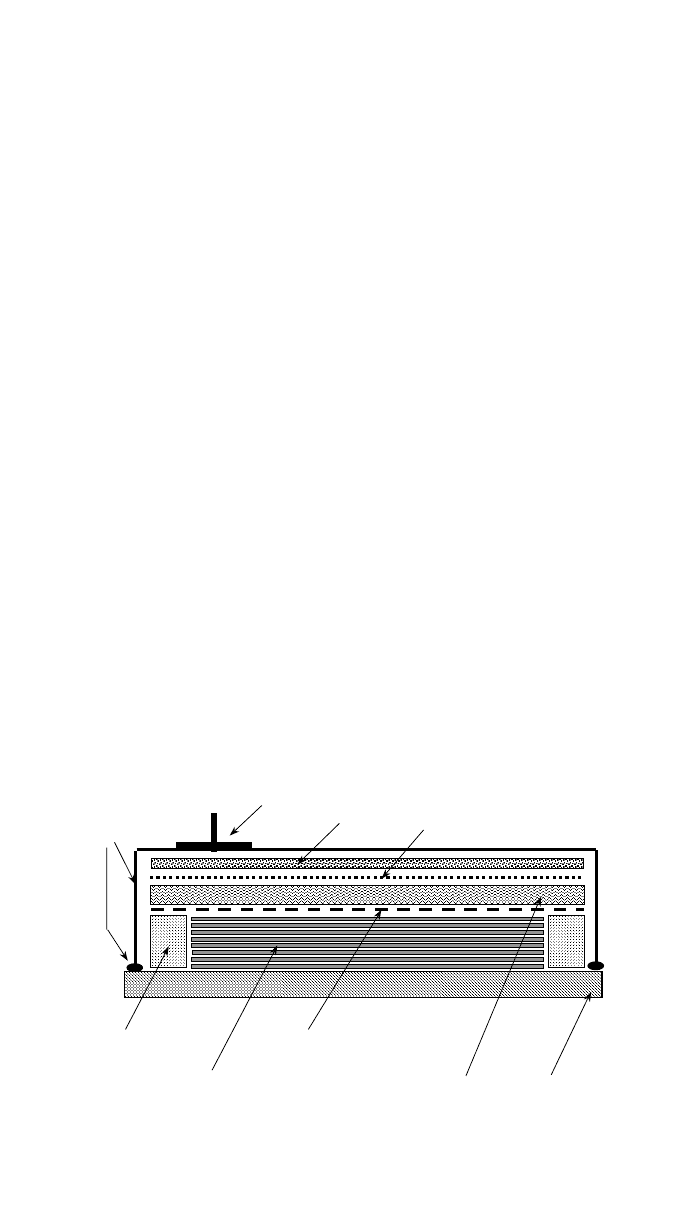
Fig. 21 Typical arrangement of prepreg laminate and auxiliary materials for autoclave molding.
The perimeter of the laminate is sealed with a cork dam that prevents outward resin flow. A
bleeder ply is set above a resin-permeable release membrane to absorb excess resin. The
breather ply ensures a continuous open passage for the vacuum application. The whole assem-
bly is covered with a vacuum bag sealed to the tool face. The vacuum connection is shown
through the bag, but an alternative is to connect through the tooling.
riphery of the molding is sealed to prevent in-plane resin bleed. This is often
done by fixing a self-adhesive cork dam to the tool face, around the edge of the
part. A semipermeable release membrane is then placed over the part. This is
most usually a fine woven glass fabric that has been coated in PTFE (Teflon).
This will allow liquid resin and gases to pass through but will not stick to the
cured part. It also imparts a fine woven texture to the back surface of the mold-
ing. A layer of porous material is then placed on top. This may be woven glass
fabric, glass or polyester mat, or even blotting paper. It serves to absorb any
excess resin bled from the curing laminate. The thickness of this bleeder layer
is adjusted according to the quantity of resin to be bled. In many current oper-
ations, zero bleed or net resin systems are used, in these cases the bleeder may
be omitted altogether and an impervious release membrane used. However, many
consider it desirable to use some bleed. On top of the bleeder is placed a further
perforated film, usually polyester or PTFE, which allows gas, but not resin, to
pass. There is then a further layer of porous fabric, usually a polyester felt,
termed the breather. This maintains a continuous gas-permeable layer over the
molding. The final layer is the vacuum bag, a polyamide (nylon) or elastomeric
film, which is sealed to the mold surface, outside the cork dam. This arrangement
is depicted in Fig. 21. A vacuum connection is made, either through the bagging
film or through the mold, so that a vacuum may be applied to the breather ply.
When this is done, atmospheric pressure will act on the vacuum bag and press
the pack onto the molding surface. The continuity within the breather and the
permeable membranes allows gases and volatiles to be extracted from the entire
pack under the bag. The vacuum is maintained while the mold is moved into
the autoclave, when the autoclave vacuum system is attached.
5.9 Autoclave Operation
The autoclave is loaded with as many molds as it will accommodate. This might
be just a single large piece, e.g., a major wing component, or several smaller
1074 COMPOSITES FABRICATION PROCESSES
250
270
290
310
330
350
370
390
410
430
450
0 50 100 150 200 250 300
TIME - min
TEMP - K
INITIAL HEATING RAMP
DWELL
SECOND HEATING RAMP
HOLD
COOL DOWN
VACUUM
APPLIED
PRESSURE
RAMP
FULL PRESSURE APPLIED
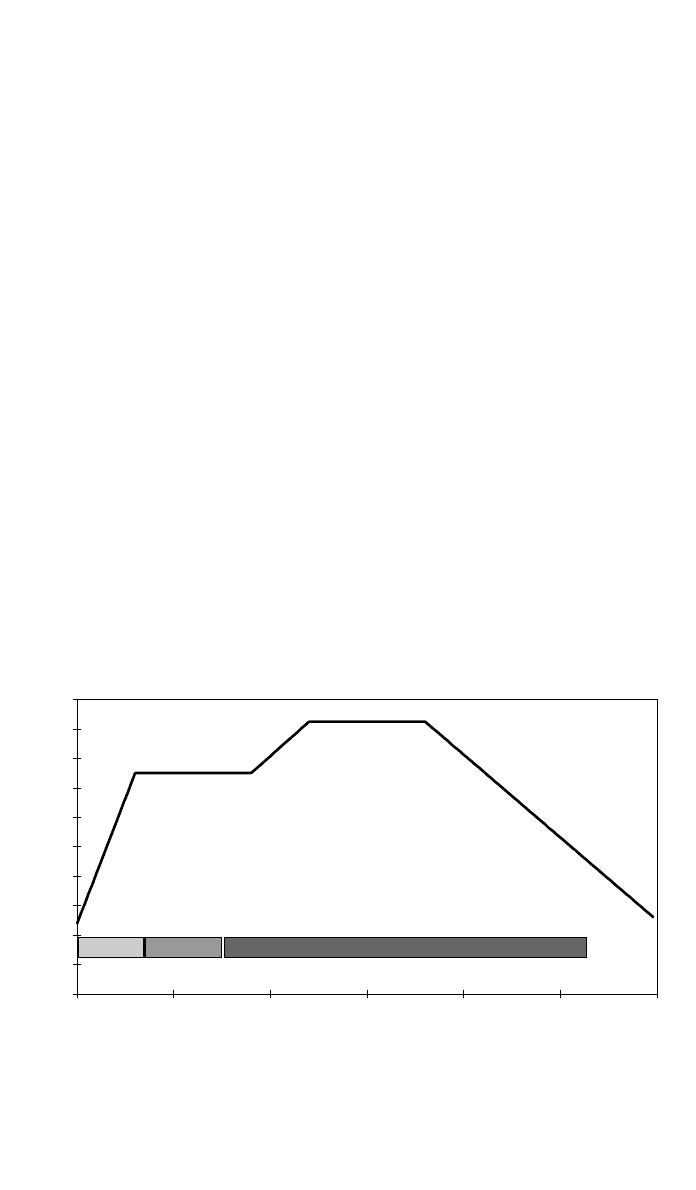
Fig. 22 Typical temperature profile for a prepreg cure cycle. The initial heat-up rate is con-
trolled, typically 5–10 K / min. The vacuum under the bag is normally maintained during heat-up.
A dwell is incorporated to assist temperature equalization in the laminate and to extend the pro-
cess window. The vacuum system is typically vented to atmosphere at this time and the con-
solidating pressure applied in the autoclave. When consolidation is completed, the temperature
is raised to the cure temperature. When cure is complete, the autoclave is allowed to cool
down to ambient temperature, with the pressure still applied. Finally the pressure is reduced so
that the autoclave may be opened and the parts removed.
panels. Each is connected to the vacuum system and temperature and cure sen-
sors connected to the central monitoring point. The autoclave may then be closed
and the cure cycle initiated. There are three controllable inputs to the cure cycle:
vacuum, pressure, and temperature. A typical cycle is depicted in Fig. 22 and
will now be described and discussed.
The autoclave is flushed out with nitrogen, to eliminate air, and may then be
pressurized. The cycle commences with the vacuum line operating and the au-
toclave at ambient temperature and pressure. The heating cycle is started. As
the resin is warmed, it softens allowing further consolidation to occur under the
pressure induced by the vacuum. Eventually the resin becomes quite fluid and
consolidation can be completed. At this stage the internal pressure is usually
increased and the vacuum lines opened to atmospheric pressure. The consoli-
dation is maintained by the difference between atmospheric pressure and the
pressure inside the autoclave. The reason for this is that with the vacuum applied,
the absolute pressure inside the molding is that of the vacuum. The autoclave
pressure is carried by solid-to-solid contact between the reinforcement fibers,
with the liquid resin effectively floating in the interfiber spaces. Any gas or vapor
porosity, effectively a bubble in the resin, will tend to dilate under these con-
ditions. By opening the space under the vacuum bag to atmospheric pressure,
this porosity will contract. A further alternative is to pressurize both the auto-
clave and the space enclosed under the bag, always maintaining a higher pressure
in the autoclave body, so as to maintain consolidation. This positive pressure
reduces pores more effectively and can even eliminate porosity by forcing air
and volatiles into solution in the liquid resin. It should be noted that the concept
5 AUTOCLAVE PROCESSING OF PREPREG 1075
200
250
300
350
400
450
500
0 50 100 150 200 250 300
TIME - min
TEMPERATURE - K
0
1
2
3
4
5
6
7
8
9
10
DEGREE OF CURE x 10
VISCOSITY
ARBITRARY UNITS
TEMPERATURE
CYCLE
PROCESSING WINDOW
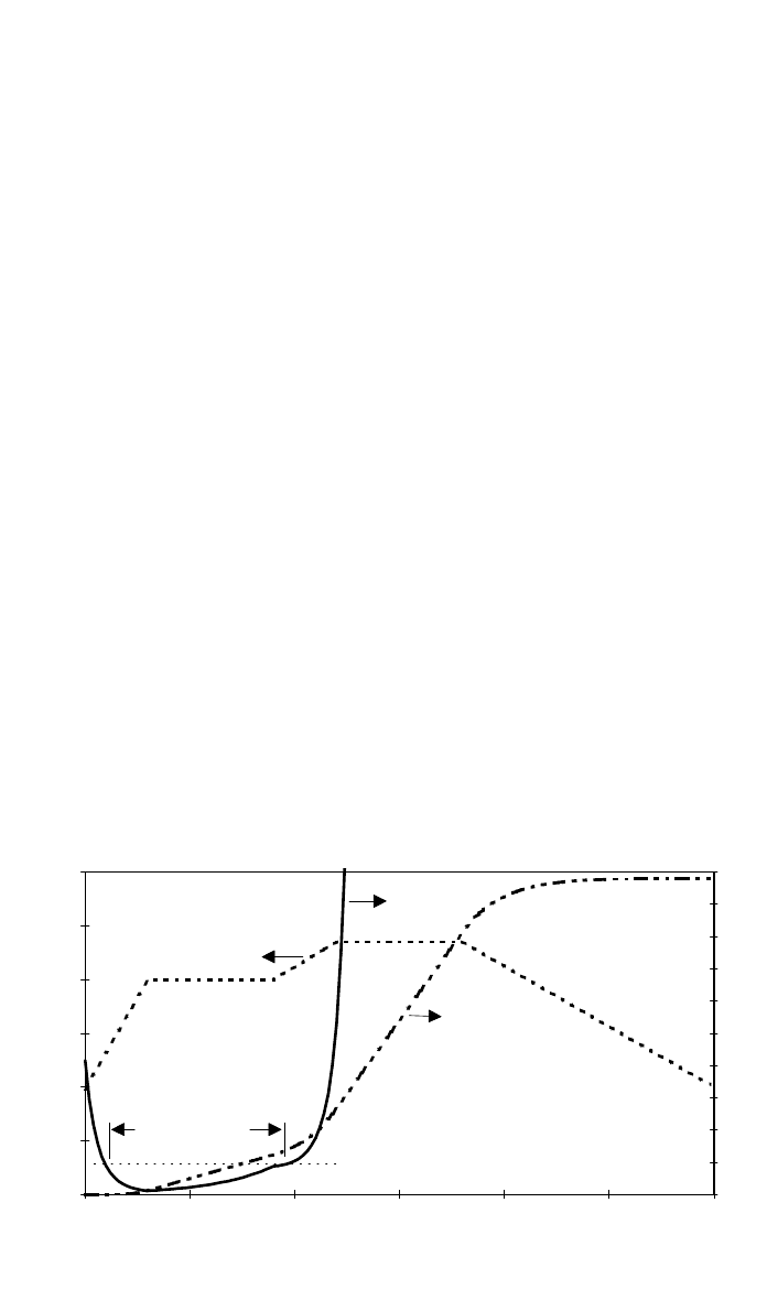
Fig. 23 Shows the cure and viscosity profiles for a typical epoxy system under the cure cycle
described in Fig. 20. Note how the period of low viscosity is extended by incorporation
of the initial dwell at 400 K.
of sucking away volatiles with the vacuum is flawed, as it would be virtually
impossible for a bubble to pass through the tightly packed prepreg fibers and
hence out through the bleeder and breather plies to the vacuum pump.
The point at which the autoclave pressure is applied can be critical. If the
resin is very fluid, too much may be squeezed out of the laminate. However, in
most systems the opposite problem dominates. This is to ensure complete con-
solidation and elimination of porosity before the resin gels. This can be exac-
erbated by the fact that the prepreg temperature will not be uniform. The outside
is heated first while the interior remains cooler. Likewise the viscosity will be
lower in the hotter regions, until the cure advances and the viscosity rises sharply
to the gel point. The problem is to create a processing window where the resin
is sufficiently fluid to allow consolidation to proceed to completion. This may
be accomplished by introducing dwell intervals in the heating cycle, as shown
in Fig. 22. The dwell or hold allows the temperatures to equilibrate in the mold-
ing and can be used to control the time at which gelation occurs. Another con-
sideration is the cure exotherm, which can result in local overheating, even in
quite thin laminates, e.g., 10 mm. This is because heat flow into and out of the
laminate is very inefficient due to the insulating characteristics of the bleeder
and breather plies in particular. A viscosity and cure profile is shown superim-
posed on the heating cycle in Fig. 23. Note that initially the resin viscosity drops
as the laminate heats up. The dwell serves to extend the time that the resin
remains at low viscosity, allowing consolidation and elimination of porosity to
proceed. When the temperature is ramped up to the final cure temperature, the
resin gels and viscosity increases sharply. At this stage the exotherm is most
intense and local overheating can result. The heating rate must be controlled to
prevent this overheating and, if necessary, a further temperature dwell is intro-
duced. The processing window is the interval when the viscosity lies below an
arbitrary level where effective consolidation will occur at the pressure employed.
