Kuppan T. Heat Exchanger Design Handbook
Подождите немного. Документ загружается.

424 Chapter
10
lines included in TEMA Standards [19] and ASME Code Section 111 [20] are presented at
appropriate places.
1
.I
Principles
of
Flow-Induced Vibration
To excite vibration, energy must be fed to the tubes. The shell-side flow represents a source
of energy that can induce and sustain tube vibration. The tubes, which are slender elastic beams
among the heat exchanger components, are disturbed from their equilibrium position and un-
dergo vibratory motion. Tube vibration is manifested by the periodic movement of the tube
from its equilibrium position. With increasing crossflow velocity the tube movement has the
following three manifestations
[
11:
1. At low crossflow velocities, the tubes vibrate with low-amplitude random motion.
2.
As the flow velocity is increased, rattling of tubes within the baffle holes takes place.
3.
As the flow velocity exceeds a threshold value, high-amplitude motion takes place.
When the natural frequencies of the tubes are closer to the exciting frequency, resonance takes
place. The relative motion between the tubes and the rigid structures like baffle supports and
shell boundary can cause impact and fretting wear of tubes.
1.2
Possible Damaging Effects
of
the FIV
on
Heat Exchangers
Flow-induced vibration can cause severe damage to the tubes and other structural components
of the heat exchanger. Mechanical failure as
a
result of tube vibration can occur from fatigue,
collision damage, baffle damage, or tube joint failures
[
11,121. These failures are discussed
next.
Midspan collision: If the amplitude of response at the midspan is greater enough, collision
with adjacent tubes takes place. The resulting wear causes failure of the tube wall under
pressure.
Wear damage at the tube interface with the baffle support: Heat exchangers are generally
designed with a clearance between the tube and the baffle plates. This clearance is required
for ease of manufacture and design considerations. Tubes that suffer lower amplitude
vibration close
to
baffle plates may fail by impact and fretting wear or fatigue.
Fatigue failures: If the contact stress due to impact or collision is greater than the allowable
fatigue stress, fretting wear takes place.
Excessive operating noise level: When the shell-side medium is a gas, steam, or air, acoustic
vibration will be induced within the tube bank containment. The acoustic vibration is
characterised by pure-tone, low-frequency intense noise.
Severe pressure drop: Since the vibration of tube requires the energy from the shell-side fluid,
the shell-side pressure drop increases. If the vibration is severe, destructive pressure fluctu-
ations take place.
Intensified stress corrosion: Due to repeated impact with the baffle supports, intensive tensile
stresses are induced on the tube surface. Susceptible tube material can fail due to the
accelerated stress corrosion cracking in the shell-side medium. However, corrosion due to
FIV
is second to the failure of tube material due to the corrosive nature of shell-side fluid
and/or tube-side fluid.
1.3
Most Probable Regions
of
Tube Failure
Although the tubes can fail anywhere in the exchanger, the regions more susceptible for flow-
induced vibration are the high-velocity regions such
as:
Flow-
Induced
Vibration
425
Largest unsupported midspan between two baffles.
Tubes located in the baffle window region at periphery of the tube bundle.
U-Bend regions
of
U-tube bundle.
Tubes located beneath the inlet nozzle.
Tubes located in the tube bundle bypass area, next to pass partition lanes.
Regionshnterfaces where there is
a
relative movement between the tube and the heat exchanger
structural components. Such regions include tube and baffle support interfaces and tube
and tube-sheet interfaces.
1.4
Failure Mechanisms
The primary failure mechanisms which cause tube failure are
[
11:
1.
Impact wear (tube-to-tube and tube-to-baffle)
2.
Fretting wear at the tube-baffle interfaces as a result of impact and/or sliding motion at
the support
3.
Combination of impact and fretting wear
1.5
Flow-Induced Vibration Mechanisms
The excitation mechanisms generally regarded as responsible for flow-induced vibration are
1.
Vortex shedding or flow periodicity
2.
Turbulent buffeting
3.
Fluid elastic instability (FEI)
4.
Acoustic resonance
Vortex shedding, turbulent buffeting, and acoustic excitation are due to resonance phenom-
ena. Resonance occurs when the excitation frequency synchronizes with a natural frequency
of the tubes. Fluid elastic instability sets in for tubes in a crossflow at a critical flow velocity
or threshold velocity resulting in amplitude of tube response large enough to collide with the
adjacent tubes and cause failure. Below the critical velocity FE1 will not take place. Instability
attains when the energy input to the tube mass-damping system exceeds the energy dissipated
by the system.
1.6
Tube Response Curve
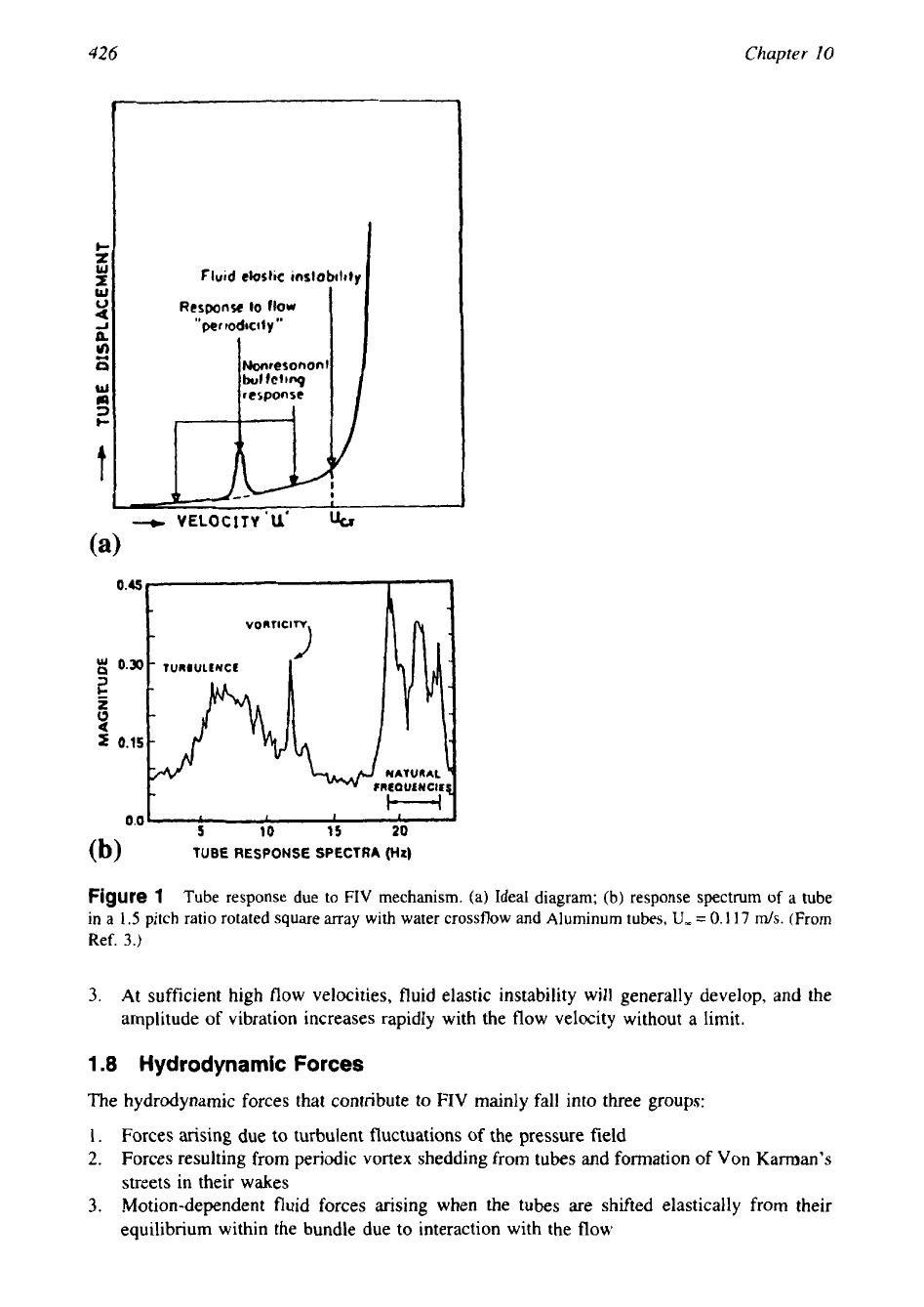
Figure
1
shows the tube response due to flow-induced vibration of tubes in tube bundles as a
result of the three excitation mechanisms, namely, vortex shedding, turbulent buffeting, and
fluid elastic instability. Each of them manifests itself only over a given range of flow parame-
ters. However, it is believed that turbulent buffeting is operative in the entire range of flow
parameters.
1.7
Dynamical Behavior of Tube Arrays in Crossflow
Flow of fluid over an array
of
elastic tubes results in
(1)
hydrodynamic effects or fluid oscilla-
tion (acoustic vibration) and
(2)
fluid-structure coupling. These effects caus hydrodynamic forces
and fluid structure coupling forces. The dynamical behavior of
an
array of cylinders
in
increasing
cross flow velocity
(U)
is considered to have three distinct manifestations as follows
[3]:
1.
At low flow velocities the cylinder respond principally to turbulent buffeting; with increas-
ing flow velocity the amplitude of tube vibration goes up roughly as
U2.
2.
At higher flow velocities, various kinds of resonance conditions may arise, such as vortex
shedding, turbulent buffeting, and acoustical oscillation of gas column.
426
Chapter
10
-,
Fluid
closlic
instability
Response
lo
flow
"periodtcily"
Mrcronont
I
bof
fcltng
--t
VELOCITY'U'
11,
;
0.30
"O
nTic'7
-
TURIUltNCf
t
0.0
'
1
5
I
10
I
15
1
20
J
(b)
TUBE
RESPONSE
SPECTRA
(Hz)
Figure
1
Tube response due to FIV mechanism. (a) Ideal diagram; (b) response spectrum of a tube
in a
1.5
pitch ratio rotated square array with water crossflow and Aluminum
tubes,
U,
=
0.1
17
m/s.
(From
Ref.
3.)
3.
At sufficient high flow velocities, fluid elastic instability will generally develop, and the
amplitude
of
vibration increases rapidly with the flow velocity without a limit.
1.8
Hydrodynamic Forces
The hydrodynamic forces that contribute
to
FIV
mainly fall into three groups:
1.
Forces arising due to turbulent fluctuations
of
the pressure field
2.
Forces resulting from periodic vortex shedding from tubes and formation of
Von
Karman's
streets in their wakes
3.
Motion-dependent fluid forces arising when the tubes are shifted elastically from their
equilibrium within the bundle due to interaction with the flow
Flow-Induced
Vibration
42
7
1.9 FIV Mechanisms Versus
Flow
Mediums
Of the different excitation mechanisms of flow induced vibration, only fluid elastic instability
is a primary concern in all flow mediums. Other mechanisms have less importance in certain
flow media. For example, turbulent buffeting is not of primary concern in gas flows since the
low density
of
the gas does not result in a very high hydrodynamic force.
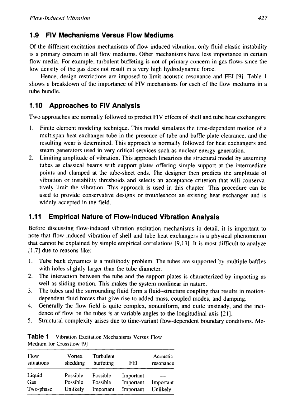
Hence, design restrictions are imposed to limit acoustic resonance and FE1 [9]. Table
1
shows a breakdown of the importance of
FIV
mechanisms for each of the flow mediums
in
a
tube bundle.
1.10 Approaches
to
FIV Analysis
Two approaches are normally followed to predict FIV effects of shell and tube heat exchangers:
1.
Finite element modeling technique. This model simulates the time-dependent motion of a
multispan heat exchanger tube in the presence of tube and baffle plate clearance, and the
resulting wear is determined. This approach is normally followed for heat exchangers and
steam generators used in very critical services such as nuclear energy generation.
2.
Limiting amplitude of vibration. This approach linearizes the structural model by assuming
tubes as classical beams with support plates offering simple support at the intermediate
points and clamped at the tube-sheet ends. The designer then predicts the amplitude of
vibration or instability thresholds and selects an acceptance criterion that will conserva-
tively limit the vibration. This approach is used in this chapter. This procedure can
be
used to provide conservative designs or troubleshoot an existing heat exchanger and is
widely accepted in the field.
1.11 Empirical Nature
of
Flow-Induced Vibration Analysis
Before discussing flow-induced vibration excitation mechanisms in detail, it is important to
note that flow-induced vibration of shell and tube heat exchangers is a physical phenomenon
that cannot be explained by simple empirical correlations [9,13]. It is most difficult
to
analyze
[
1,7] due to reasons like:
1.
Tube bank dynamics is a multibody problem. The tubes are supported by multiple baffles
with holes slightly larger than the tube diameter.
2.
The interaction between the tube and the support plates is characterized by impacting as
well as sliding motion. This makes the system nonlinear in nature.
3. The tubes and the surrounding fluid form
a
fluid-structure coupling that results in motion-
dependent fluid forces that give rise to added mass, coupled modes, and damping,
4.
Generally the flow field is quite complex, nonuniform, and quite unsteady, and the inci-
dence of flow on the tubes is at variable angles to the longitudinal axis
[21].
5.
Structural complexity arises due to time-variant flow-dependent boundary conditions. Me-
Table
1
Vibration Excitation Mechanisms Versus
Flow
Medium for Crossflow
[9]
~~~~~
Flow Vortex
Turbulent Acoustic
situations shedding buffeting
FE1 resonance
Liquid Possible Possible
Important
-
Gas Possible Possible
Important Important
Two-phase Unlikely Important Important
Unlikely
428
Chapter
10
chanical tolerances, initial straightness, fit-up, and tube buckling due to manufacturing
process add complexities in defining boundary conditions
[22].
6.
Effects of tube bundle parameters such
as
transverse and longitudinal pitches, tube layout
pattern, pass partition lanes, shell to tube bundle clearance, number of tube rows, etc.
on
the occurrence of
FIV
cannot be correctly evaluated. The effects of some parameters have
been studied by Gorman
[23].
For these reasons, most of the methods in the analysis of tube bank dynamics are semiemp-
irical
in
nature.
To
render the problem amenable for most analytical studies and experimental
investigations, the flow conditions are idealized as:
1.
The flow is uniform and steady
2.
The incident of the flow is either axial or normal to the tubes.
3.
The tube motion is linearized and it is assumed that the frequencies are well defined.
4.
The baffle supports provide a simply supported condition.
2
DISCUSSION OF FLOW-INDUCED VIBRATION MECHANISMS
2.1
Vortex
Shedding
Single tube
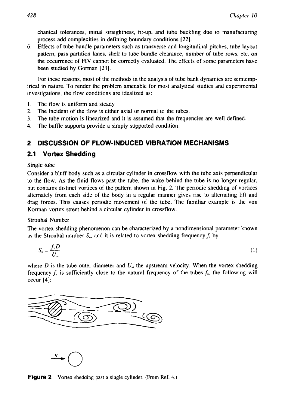
Consider a bluff body such as a circular cylinder in crossflow with the tube axis perpendicular
to the flow.
As
the fluid flows past the tube, the wake behind the tube is no longer regular,
but contains distinct vortices of the pattern shown in Fig.
2.
The periodic shedding of vortices
alternately from each side of the body in a regular manner gives rise to alternating lift and
drag forces. This causes periodic movement of the tube. The familiar example is the von
Korman vortex street behind a circular cylinder in crossflow.
Strouhal Number
The vortex shedding phenomenon can be characterized by a nondimensional parameter known
as the Strouhal number
S,,
and it is related to vortex shedding frequencyf, by
where
D
is the
tube outer diameter and
U,
the upstream velocity. When the vortex shedding
frequency
f\
is
sufficiently close to the natural frequency of the tubes
fn,
the following will
occur
[4]:
"0
Figure
2
Vortex shedding
past
a
single cylinder. (From Ref.
4.)
429
Flow-
Induced Vibration
1.
The vortex shedding frequency shifts to the structural natural frequency, developing the
condition called "lock-in" or "synchronization." The lock-in phenomena leads to high-
amplitude vibration with substantial energy input to the tube.
2.
The lift force becomes a function of structural amplitude.
3.
The drag force on the structure increases. However, the magnitude of the oscillating drag
force is smaller than the oscillating lift force. Also the drag force occurs at twice the
vortex shedding frequency.
4.
The strength of the shed vortices increases
When the vortex shedding frequency coincides with the tube natural frequency or close to
the natural frequency, resonance takes place. Resonance is characterized by large amplitudes
of tube motion with possible damage to the tube. This mechanism has been variously referred
to as vortex shedding, periodic wake shedding, Strouhal periodicity, or Strouhal excitation.
Since the vortex shedding drag force in the streamwise direction (drag) occurs at twice
the vortex shedding frequency and the magnitude of drag force is smaller than the oscillating
lift force, normally the analysis is carried out for lift forces only.
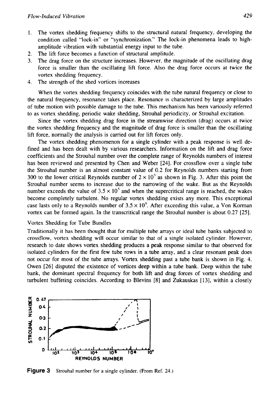
The vortex shedding phenomenon for a single cylinder with a peak response is well de-
fined and has been dealt with by various researchers. Information on the lift and drag force
coefficients and the Strouhal number over the complete range of Reynolds numbers of interest
has been reviewed and presented by Chen and Weber
[24].
For crossflow over a single tube
the Strouhal number is an almost constant value of
0.2
for Reynolds numbers starting from
300
to the lower critical Reynolds number of
2
x
105 as shown in Fig.
3.
After this point the
Strouhal number seems to increase due to the narrowing of the wake. But as the Reynolds
number exceeds the value of
3.5
x
105
and when the supercritical range is reached, the wakes
become completely turbulent.
No
regular vortex shedding exists any more. This exceptional
case lasts only to a Reynolds number of
3.5
x
106. After exceeding this value, a Von Korman
vortex can be formed again. In the transcritical range the Strouhal number is about
0.27 [25].
Vortex Shedding for Tube Bundles
Traditionally it has been thought that for multiple tube arrays or ideal tube banks subjected to
crossflow, vortex shedding will occur similar to that of a single isolated cylinder. However,
research to date shows vortex shedding produces a peak response similar to that observed for
isolated cylinders for the first few tube rows in
a
tube array, and a clear resonant peak does
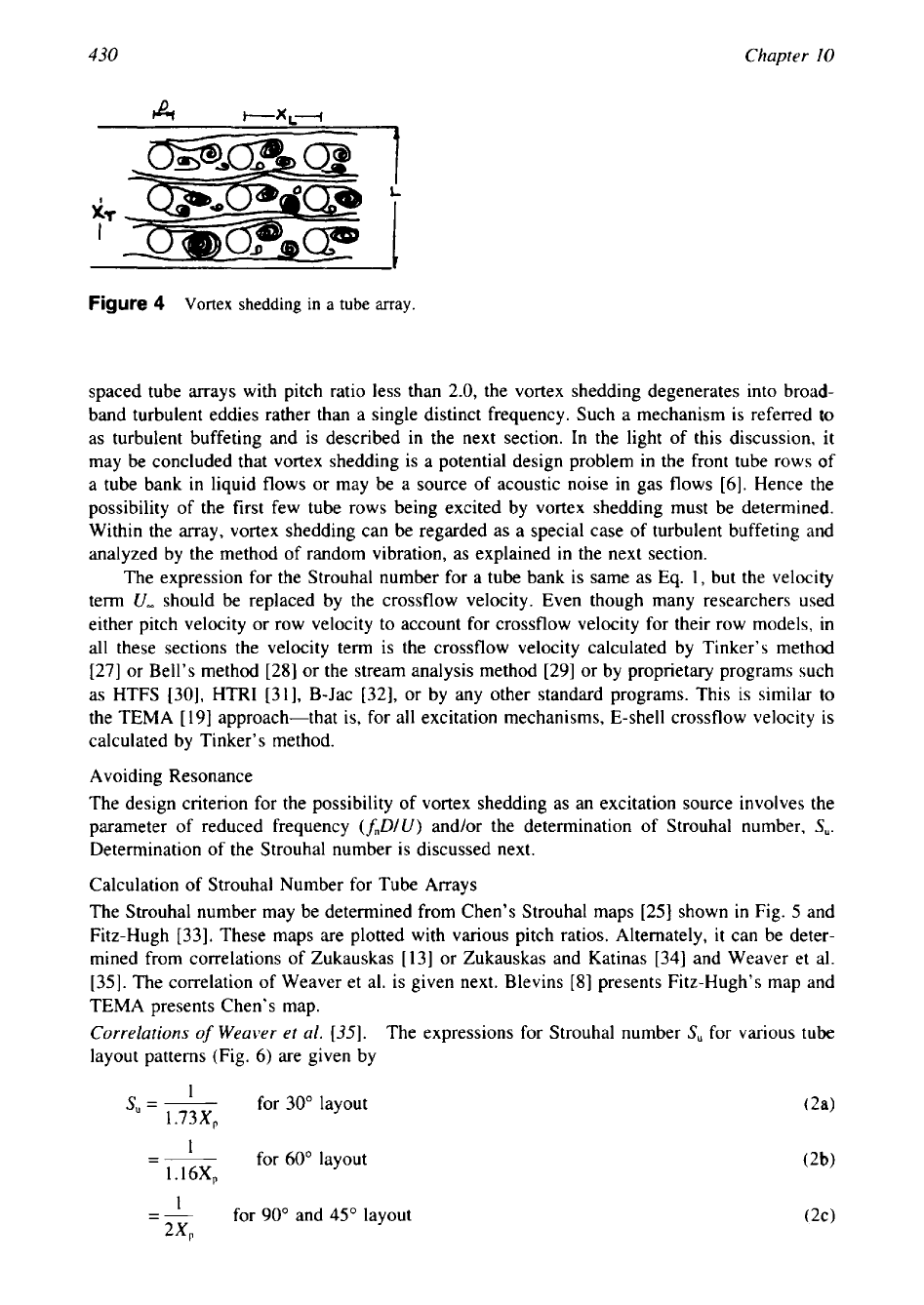
not occur for most of the tube arrays. Vortex shedding past a tube bank is shown in Fig.
4.
Owen
[26]
disputed the existence of vortices deep within a tube bank. Deep within the tube
bank, the dominant spectral frequency for both lift and drag forces of vortex shedding and
turbulent buffeting coincides. According to Blevins
[8]
and Zukauskas
[
131,
within a closely
P
Figure
3
Strouhal number for
a
single
cylinder. (From Ref.
24.)
--
430
Chapter
I0
f
L
Figure
4
Vortex
shedding
in
a
tube
array.
spaced tube arrays with pitch ratio less than 2.0, the vortex shedding degenerates into broad-
band turbulent eddies rather than a single distinct frequency. Such a mechanism is referred
to
as turbulent buffeting and is described in the next section. In the light of this discussion, it
may be concluded that vortex shedding is a potential design problem in the front tube rows
of
a tube bank in liquid flows or may be a source of acoustic noise in gas flows [6]. Hence the
possibility of the first few tube rows being excited by vortex shedding must be determined.
Within the array, vortex shedding can be regarded as a special case of turbulent buffeting and
analyzed by the method of random vibration, as explained in the next section.
The expression for the Strouhal number for a tube bank is same as Eq.
1,
but the velocity
term
U,
should be replaced by the crossflow velocity. Even though many researchers used
either pitch velocity or row velocity to account for crossflow velocity for their row models, in
all
these sections the velocity term is the crossflow velocity calculated by Tinker's method
[27] or Bell's method [28] or the stream analysis method [29] or by proprietary programs such
as HTFS [30], HTRI [31], B-Jac 1321, or by any other standard programs. This is similar
to
the TEMA
[
191 approach-that is, for all excitation mechanisms, E-shell crossflow velocity
is
calculated by Tinker's method.
Avoiding Resonance
The design criterion for the possibility of vortex shedding as an excitation source involves the
parameter of reduced frequency
(f,D/U)
and/or the determination of Strouhal number,
S,.
Determination of the Strouhal number is discussed next.
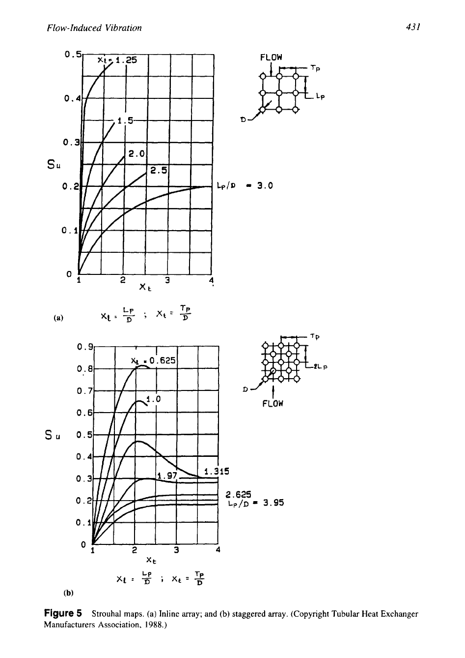
Calculation of Strouhal Number for Tube Arrays
The Strouhal number may be determined from Chen's Strouhal maps [25] shown
in
Fig.
5
and
Fitz-Hugh [33]. These maps are plotted with various pitch ratios. Alternately, it can be deter-
mined from correlations of Zukauskas
[
131 or Zukauskas and Katinas [34] and Weaver et al.
[35]. The correlation of Weaver et al. is given next. Blevins [S] presents Fitz-Hugh's map and
TEMA presents Chen's map.
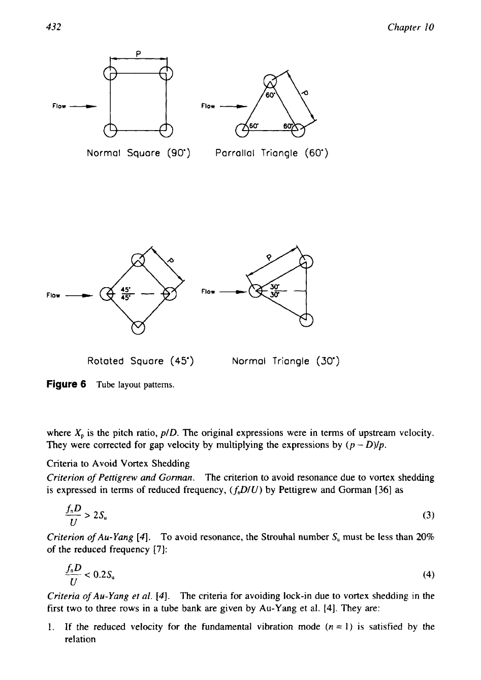
Correlations
of
Weaver et al.
[35].
The expressions for Strouhal number
S,
for various tube
layout patterns (Fig.
6)
are given by
s,
=
for 30" layout
(2a)
~
1.73XP
-
I
for
60"
layout
(2b)
1.16XP
---
for 90" and
45"
layout
2%
431
Flow-Induced
Vibration
FLOW
su
=
3.0
D
FLOW
su
Figure
5
Strouhal maps. (a) Inline array; and
(b)
staggered array. (Copyright Tubular Heat Exchanger
Manufacturers Association,
1988.)
432
Chapter
I0
Flow
Flow
Normal Square
(90')
Parrallal Triangle
(60')
Rotated
Squore
(45')
Normal Triangle
(30')
Figure
6
Tube
layout patterns.
where
Xp
is the pitch ratio,
plD.
The original expressions were in terms of upstream velocity.
They were corrected for gap velocity by multiplying the expressions by
(p
-
D)/p.
Criteria to Avoid Vortex Shedding
Criterion
of
Pettigrew and Gorman.
The criterion to avoid resonance due to vortex shedding
is expressed in terms of reduced frequency,
(JDlU)
by Pettigrew and Gorman
[36]
as
f"D
-
>
ZS,
(3)
U
Criterion
of
Au-Yang
[4].
To
avoid resonance, the Strouhal number
S,
must be less than
20%
of the reduced frequency
[7]:
f"D
-
<
0.2s"
(4)
U
Criteria
of
Au-Yang et al.
[4].
The criteria for avoiding lock-in due to vortex shedding
in
the
first two
to
three rows in a tube bank are given by Au-Yang et al.
[4].
They are:
1.
If the reduced velocity for the fundamental vibration mode
(n
=
1)
is satisfied by the
relation
____
433
Flow-Induced
Vibration
(5)
both lift and drag direction lock-in are avoided.
For a given vibration mode if the reduced damping
Cn
is large enough,
C,
>
64
then lock-in will be suppressed in that vibration mode.
If for a given vibration mode
TT
U
-
<
3.3
(7)
fnD
and
C,,
>
1.2,
then lift direction lock-in is avoided and drag direction lock-in is suppressed.
The reduced damping
C,
is calculated by the equation
is the tube length subject to vortex shedding, and
Cp,,(x)
is
for
M,
is given by
where
m(x)
is
the tube mass per unit length. Substituting the expression for the modal
mass and normalizing the mode shape, the expression for reduced damping
C,,
is given by
c,
=
4n5nm
when
M,
=
m(x)
=
m
p5D2
These guidelines are included in
ASME
Code Section 111.
In the preceding equations,f, is the tube natural frequency,
m
is the effective tube mass
per unit length, and
cn
is the critical damping ratio. The effective tube mass is the
sum
of
structural mass, fluid added mass due to the contribution of shell-side fluid displaced by the
vibrating tube, and the mass of the contained fluid per unit length. In simple terms,
rn
=
structural mass
+
added mass
+
contained fluid mass
=
m,+
m,
+
m,
(1
1)
where
m,
is the added mass per unit length,
mi
the contained fluid mass per unit length, and
m,
the structural mass per unit length. The terms
pi,
ps,
and p are density
of
tube-side fluid,
shell-side fluid, and tube metal, respectively. The added mass involves a term called added
mass coefficient,
C,.
The determination of&,
C,,
and critical damping ratio
k,,
are discussed
at the end of this section.
Response Due to Vortex Shedding Vibration Prediction by Dynamic Analysis
If resonance occurs, the maximum tube response can be obtained by a forced response analysis
as described in refs.
4
and
36.
Sandifer
[9]
describes this from first principles. The generalized
equation for the tube response
y(x)
for any mode number
j
is given by [36]: