Kuppan T. Heat Exchanger Design Handbook
Подождите немного. Документ загружается.

434
Chapter
10
(13)
The mode shape in Eq.
13
is normalized by
I-,
I$'(x)
dx
=
1
1)
and evaluation of this integral gives
=$
(maximum value)
After normalizing the modal mass, the maximum response
y,,,
is given by
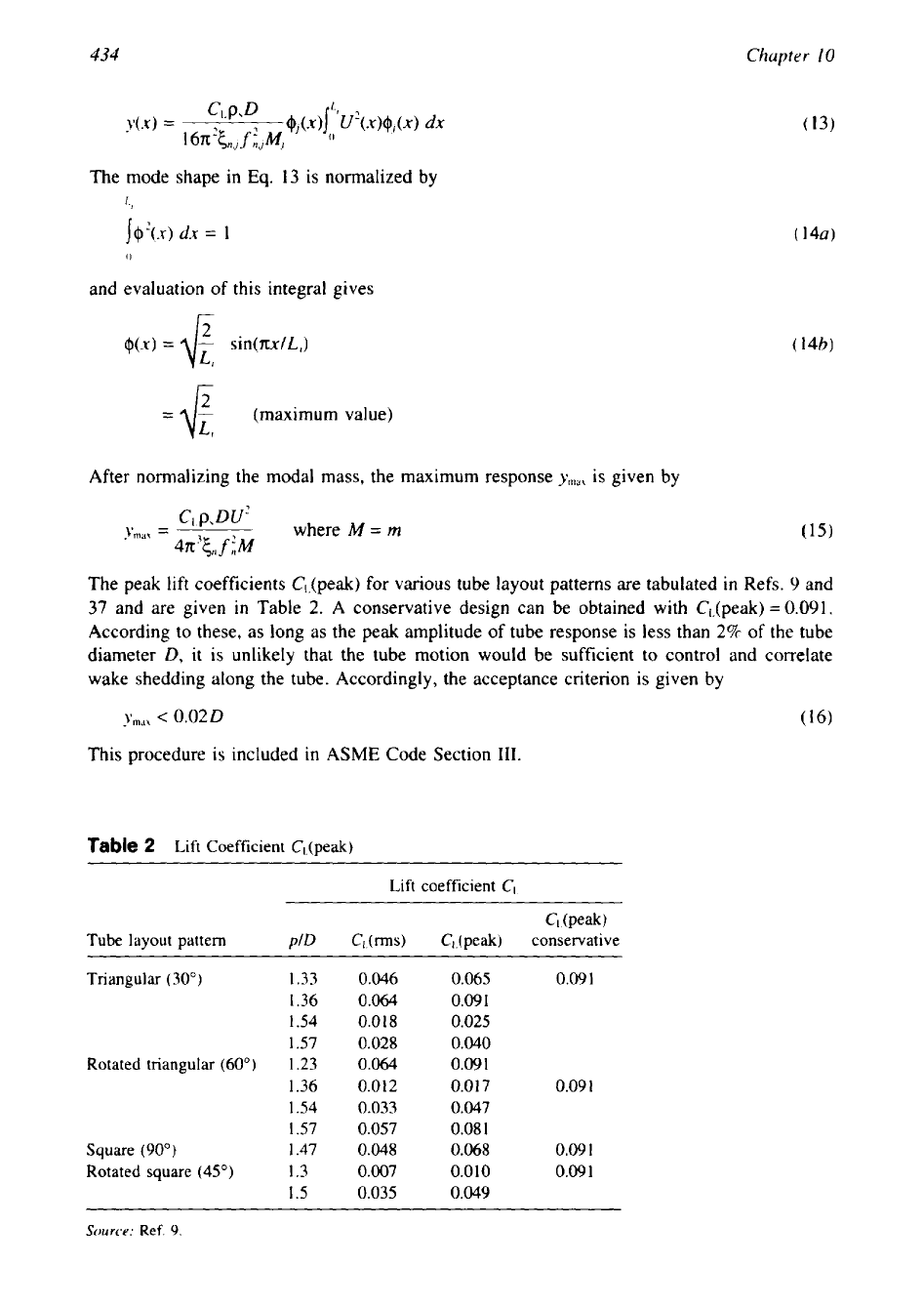
The peak
lift
coefficients Cl-(peak) for various tube layout patterns are tabulated
in
Refs.
9
and
37
and are given
in
Table
2.
A conservative design can be obtained with Cl,(peak)
=
0.091.
According to these, as long as the peak amplitude of tube response is less than
2%
of the tube
diameter
D,
it is unlikely that the tube motion would be sufficient to control and correlate
wake shedding along the tube. Accordingly, the acceptance criterion is given by
y,,,
c
0.020
(16)
This procedure is included in ASME Code Section
111.
Table
2
Lift Coefficient C,-(peak)
Lift coefficient
C,
Cdpeak)
Tube layout pattern
plD
C,(rms)
CJpeak) conservative
Triangular
(30") 1.33
0.046
0.065
0.09
I
1.36
0.064
0.09
1
1.54
0.018
0.025
1.57
0.028
0.040
Rotated triangular
(60")
I
.23 0.064
0.09
1
1.36 0.012
0.017
0.09
1
1.54
0.033
0.047
1.57
0.057
0.08
1
Square
(90")
1.47
0.048
0.068
0.09
1
Rotated square
(45") 1.3 0.007
0.0
10
0.09
1
1.5
0.035
0.049
Source:
Ref.
9.
Flow-Induced
Vibration
435
3
TURBULENCE-INDUCED EXCITATION
3.1
Turbulence
In general, higher flow rates promote and maintain high turbulence
in the fluid, which is
desirable for enhanced heat transfer, but the high turbulence is a source of structural excitation.
Heat exchanger tubes respond in a random manner to turbulence
in
the flow field.
In
addition
to structural excitation, turbulence in the flow can affect the existence and strength of other
excitation mechanism, namely, vortex shedding.
3.2
Turbulent Buffeting
Turbulent buffeting in a tube bank, sometimes called subcritical vibration, refers to the low-
amplitude response before the critical velocity is reached and away from the vortex lock-in
velocity region due to unsteady forces developed on a body exposed to a high turbulence
in
the flow field.
The turbulent flow has been characterised by random velocity perturbations associated
with turbulent eddies spread over a wide range of frequencies distributed around a central
dominant frequency. When the dominant central frequency in the flow field coincides with the
lowest natural frequency of the tube, a considerable amount of energy transfer takes place,
leading to resonance and high-amplitude tube vibration. Even
in
the absence of resonance,
turbulent buffeting can cause fretting wear and fatigue failure. With a design objective of
40
years codal life for nuclear power plant steam generators and heat exchangers, even relatively
small tube wear rates cannot be acceptable [6,38]. Hence, turbulence excitation becomes an
important design consideration
in
the design of reliable heat exchangers.
3.3
Owen’s
[26]
Expression for Turbulent Buffeting Frequency
Based on experimental study of gas flow normal to a tube bank, Owen
[26]
correlated an
expression for the central dominant frequency of the turbulent buffeting,
A,,,
as
U
fih
=
where
x,
=
longitudinal pitch ratio
=
L,/
D
(Lp
is longitudinal pitch)
x,
=
transverse pitch ratio
=
T,/D
(T,
is transverse pitch)
Weaver and Grover [39] reviewed various works and observed that Owen’s approach is
most reliable for predicting the peak frequency in the turbulence, provided the minimum gap
velocity is used in the expression. The preceding correlation is applicable for a tube bank with
transverse pitch ratio more than
1.25.
Since this correlation has not been tested for liquids,
it
should be restricted to gases only. TEMA has included this expression.
3.4
Turbulent Buffeting Excitation
as
a Random Phenomenon
By assuming that the tube vibrations represent steady-state random process, expression for rms
amplitude of tube response have been developed by Au-Yang et al.
[4],
Au-Yang
[7],
and
Pettigrew and Gorman 1361. Sandifer [9] describes the equation for tube response from first
principles. The mean square resonant response of a lightly damped structure is given by:
436
Chapter
10
After normalizing the mode shape over the span length and for the first mode of vibration,
the
maximum mean square response is given by
.-
-1
[Cd
f
)p,u’DJ
4‘m’l.i
=
where
M
=
rn
128n35,
f
iM2
Ymlr
=
tlv,,,z
A
recommended acceptance criterion is
ym,
I
0.010
in or 0.254 mm
(20)
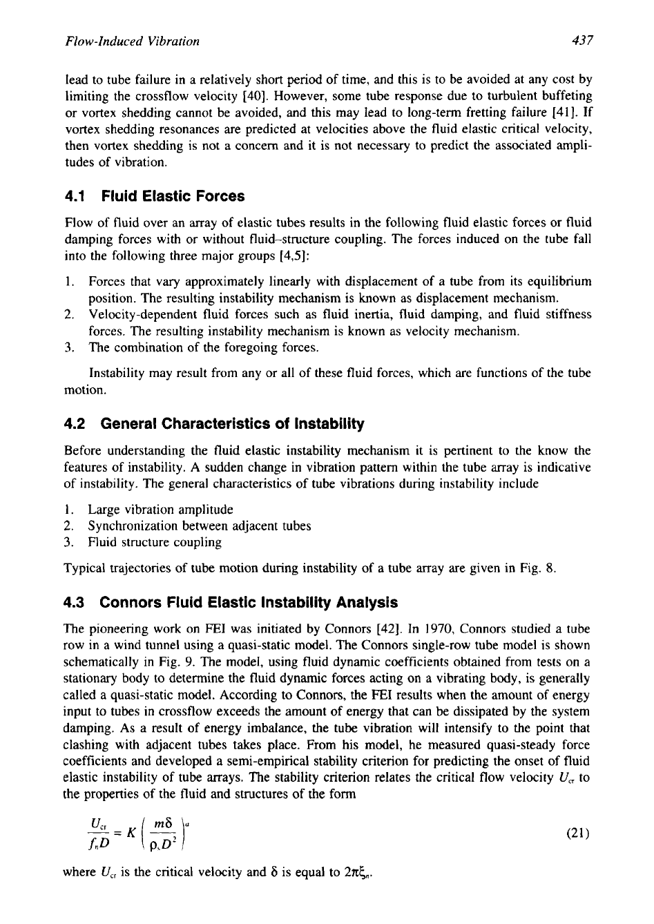
The parameter
CR(J>
can be determined from the Fig.
7
[36].
These guidelines are included in
ASME
Code Sec.
111.
4
FLUID ELASTIC INSTABILITY
A
group of circular cylinders submerged in crossflow can be subjected to dynamic instability,
typically referred to as fluid elastic instability. Fluid elastic vibration sets in at a critical flow
velocity and can become of large amplitude if the flow is increased further. The familiar
examples of
FE1
vibration are aircraft wing flutter, transmission line galloping, and vibration
of tube arrays
in
heat exchangers.
A
sudden change in vibration pattern within the tube array indicates instability and is
attained when the energy input to the tube mass-damping system exceeds the energy dissipated
by the system. Fluid elastic instability has been recognized as a mechanism that will almost
t
Figure
7
Random
excitation force co-efficient,
CR.
(From Ref.
36.)
Flow-Induced
Vibration
437
lead to tube failure in a relatively short period of time, and this is to be avoided at any cost by
limiting the crossflow velocity [40]. However, some tube response due to turbulent buffeting
or vortex shedding cannot be avoided, and this may lead to long-term fretting failure [41]. If
vortex shedding resonances are predicted at velocities above the fluid elastic critical velocity,
then vortex shedding is not a concern and it is not necessary to predict the associated ampli-
tudes
of
vibration.
4.1 Fluid Elastic Forces
Flow of fluid over an array of elastic tubes results in the following fluid elastic forces or fluid
damping forces with
or
without fluid-structure coupling. The forces induced on the tube fall
into the following three major groups [4,5]:
I.
Forces that vary approximately linearly with displacement of a tube from its equilibrium
position. The resulting instability mechanism is known as displacement mechanism.
2.
Velocity-dependent fluid forces such as fluid inertia, fluid damping, and fluid stiffness
forces. The resulting instability mechanism is known as velocity mechanism.
3.
The combination of the foregoing forces.
Instability may result from any or all of these fluid forces, which are functions
of
the tube
motion.
4.2
General Characteristics
of
Instability
Before understanding the fluid elastic instability mechanism it is pertinent to the know the
features of instability.
A
sudden change in vibration pattern within the tube array is indicative
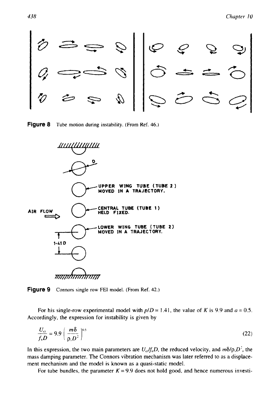
of instability. The general characteristics of tube vibrations during instability include
1. Large vibration amplitude
2. Synchronization between adjacent tubes
3.
Fluid structure coupling
Typical trajectories of tube motion during instability of a tube array are given in Fig.
8.
4.3
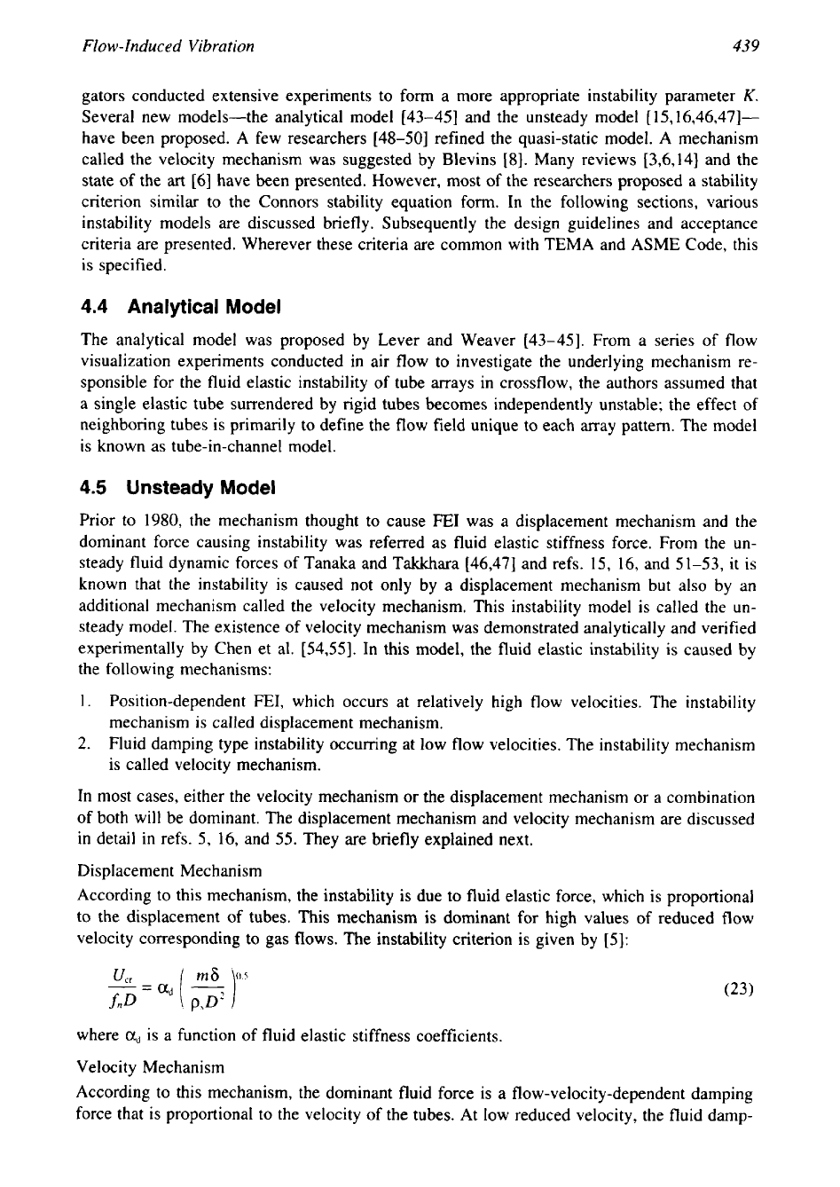
Connors Fluid Elastic Instability Analysis
The pioneering work on FE1 was initiated by Connors [42]. In 1970, Connors studied a tube
row in a wind tunnel using a quasi-static model. The Connors single-row tube model is shown
schematically in Fig. 9. The model, using fluid dynamic coefficients obtained from tests on a
stationary body to determine the fluid dynamic forces acting on a vibrating body, is generally
called a quasi-static model. According to Connors, the
FE1
results when the amount of energy
input to tubes in crossflow exceeds the amount of energy that can be dissipated by the system
damping.
As
a result of energy imbalance, the tube vibration will intensify to the point that
clashing with adjacent tubes takes place. From his model, he measured quasi-steady force
coefficients and developed a semi-empirical stability criterion for predicting the onset of fluid
elastic instability of tube arrays. The stability criterion relates the critical flow velocity
U,,
to
the properties of the fluid and structures of the form
where
U,,
is the critical velocity and
6
is
equal to
27&.
438
Chapter
10
/
0
"0
Figure
8
Tube motion during instability. (From Ref.
46.)
UPPER
WING
TUBE (TUBE
2
)
MOVED IN
A
TRAJECTORY.
AIR
FLOW
L--3
CENTRAL TUBE
(TUBE
1)
HELD
FIXED.
LOWER
WING
TUBE (TUBE
2)
MOVED
IN
A
TRAJECTORY.
1-41
0
Figure
9
Connors single row
FE1
model. (From Ref. 42.)
For his single-row experimental model with
p/D
=
1.41,
the value of
K
is
9.9
and
a
=
0.5.
Accordingly, the expression for instability is given by
In this expression, the two main parameters are
Uc,lfnD,
the reduced velocity, and
m6/p,D2,
the
mass damping parameter. The Connors vibration mechanism was later referred to as a displace-
ment mechanism and the model
is
known
as
a quasi-static model.
For tube bundles, the parameter
K=
9.9
does not hold good, and hence numerous investi-
Flow-
Induced
Vibration
439
gators conducted extensive experiments to form a more appropriate instability parameter
K.
Several new models-the analytical model [43-451 and the unsteady model
[
15, I6,46,47]-
have been proposed. A few researchers [48-501 refined the quasi-static model. A mechanism
called the velocity mechanism was suggested by Blevins [8]. Many reviews [3,6,14] and the
state of the
art
[6] have been presented. However, most of the researchers proposed a stability
criterion similar to the Connors stability equation form. In the following sections, various
instability models are discussed briefly. Subsequently the design guidelines and acceptance
criteria are presented. Wherever these criteria are common with TEMA and ASME Code, this
is specified.
4.4 Analytical Model
The analytical model was proposed by Lever and Weaver [43-451. From a series of flow
visualization experiments conducted in air flow to investigate the underlying mechanism re-
sponsible for the fluid elastic instability of tube arrays in crossflow, the authors assumed that
a single elastic tube surrendered by rigid tubes becomes independently unstable; the effect of
neighboring tubes is primarily to define the flow field unique to each array pattern. The model
is known as tube-in-channel model.
4.5
Unsteady
Model
Prior to 1980, the mechanism thought to cause FE1 was a displacement mechanism and the
dominant force causing instability was referred as fluid elastic stiffness force. From the un-
steady fluid dynamic forces of Tanaka and Takkhara [46,47] and refs. 15, 16, and 51-53, it is
known that the instability is caused not only by a displacement mechanism but also by an
additional mechanism called the velocity mechanism. This instability model is called the un-
steady model. The existence of velocity mechanism was demonstrated analytically and verified
experimentally by Chen et al. [54,55]. In this model, the fluid elastic instability is caused by
the following mechanisms:
1.
Position-dependent
FEI,
which occurs at relatively high flow velocities. The instability
mechanism
is
called displacement mechanism.
2.
Fluid damping type instability occurring at low flow velocities. The instability mechanism
is called velocity mechanism.
In most cases, either the velocity mechanism or the displacement mechanism or a combination
of both will be dominant. The displacement mechanism and velocity mechanism are discussed
in detail
in
refs.
5,
16,
and 55. They are briefly explained next.
Displacement Mechanism
According to this mechanism, the instability is due to fluid elastic force, which is proportional
to the displacement of tubes. This mechanism is dominant for high values of reduced flow
velocity corresponding to gas flows. The instability criterion is given by
[5]:
where
a,
is a function of fluid elastic stiffness coefficients.
Velocity Mechanism
According to this mechanism, the dominant fluid force is a flow-velocity-dependent damping
force that is proportional to the velocity of the tubes. At low reduced velocity, the fluid damp-
440
Chapter
10
ing force may act as an energy dissipation mechanism, whereas at high reduced velocities it
acts as an excitation mechanism. When it acts as an excitation mechanism, the system damping
is reduced. The tube loses stability once the modal damping of a mode becomes negative. This
type of instability
is
called fluid damping controlled instability, and it is dominant for
low
values of reduced velocities that correspond to liquid flow. The instability criterion is given
by
151:
where
a,
is a function
of
fluid damping coefficients.
Unsteady Model
Based on the displacement mechanism and velocity mechanism, the dynamics of the tube array
in simple form is written as
[16]:
[W
+
Mf]{q)
+
[C,
+
Cr
+
CVl{4)
+
[K
+
Kdq)
=
[FI
(25)
where
[M,]
=
structural mass
[M,]
=
added mass of the fluid
[C,]
=
structural damping of the system
[C,]
=
viscous damping of the still fluid
[C,]
=
velocity-dependent damping
of
the fluid
[K,]
=
structural stiffness
[
K,]
=
fluid elastic stiffness
[F]
=
fluid forces independent
of
the tube motion
{
q}
=
structural displacement
(4)
=
structural velocity
{q)
=
structural acceleration
In the preceding expression the terms in square brackets are matrices and those in braces are
vectors. The constituents of fluid dynamic forces are
1.
[Mf]
{q},
fluid inertia force
2.
[C,
+
C,]{q},
fluid damping force
3.
[Kf]{q},
fluid elastic force
The major obstacle in the analysis of the instability mechanism by the unsteady model is
to determine the flow-velocity-dependent damping
[CJ
and fluid stiffness
[Kf]
for every tube
layout pattern and for the entire range
of
reduced flow velocity of interest, either analytically
or experimentally. These forces were measured experimentally by Tanaka and Takkahara
[47].
4.6
Design Recommendations
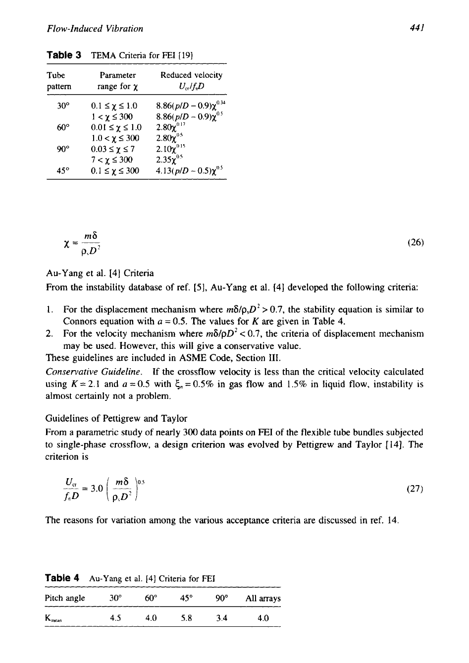
Chen’s Criterion
From the data of many investigators, Chen
[5]
recommended a criterion for the lower bound
of critical velocity. Later, Chen
[56]
revised the criteria as shown in Table
3
where the expres-
sion for
x
is given. TEMA included this criterion.
The
notable feature of Chen’s criterion is
the presence of pitch ratio
(plD)
in the equation:
441
Flow-Induced Vibration
Table
3
TEMA Criteria for
FE1
[
191
Tube Parameter Reduced velocity
pattern range for
x
UCAfno
30"
0.1
I
x
I
1.0
8.86(p/D
-
0.9)~"~
1
<
x
5
300
8.86(p/D
-
0.9)~"~
60"
0.01
I
x
5
1.0
2.80~""
1
.O
c
x
5
300
2.80~'
90"
0.03
I
x
5
7
2.
lOx'
l5
7
c
x
I300 2.35~'~
45"
0.1
I
x
I300
4.13(p/D
-
0.5)~~)~
Au-Yang et al.
[4]
Criteria
From the instability database of ref.
[S],
Au-Yang et al.
[4]
developed the following criteria:
1.
For the displacement mechanism where
m6/psDZ
0.7,
the stability equation is similar to
Connors equation with
a
=
0.5.
The values for
K
are given in Table
4.
2.
For the velocity mechanism where
m6/pD2
<
0.7,
the criteria of displacement mechanism
may be used. However, this will give a conservative value.
These guidelines are included in ASME
Code,
Section
111.
Conservative Guideline.
If
the crossflow velocity is less than the critical velocity calculated
using
K
=
2.1 and
a
=
0.5
with
cn
=
0.5% in
gas
flow and 1.5% in liquid flow, instability is
almost certainly not a problem.
Guidelines of Pettigrew and Taylor
From a parametric study of nearly
300
data points on
FE1
of
the flexible tube bundles subjected
to single-phase crossflow, a design criterion
was
evolved by Pettigrew and Taylor
[14].
The
criterion is
The reasons for variation among the various acceptance criteria are discussed in ref.
14.
Table
4
Au-Yang et al.
[4]
Criteria for
FE1
Pitch angle
30"
60"
45"
90"
All
arrays
Kma"
4.5
4.0
5.8
3.4
4.0
442
Chapter
10
4.7
Acceptance Criteria
To
avoid
FEI,
the acceptance criteria are:
1. Normal criterion:
2.
Conservative criterion,
[9]:
4.8
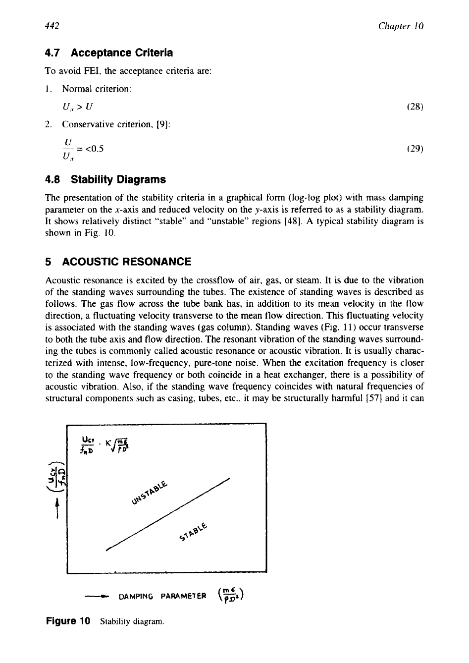
Stability Diagrams
The presentation of the stability criteria in a graphical form (log-log plot) with mass damping
parameter on the x-axis and reduced velocity on the y-axis is referred to as a stability diagram.
It shows relatively distinct “stable” and “unstable” regions
[48].
A
typical stability diagram is
shown in Fig. 10.
5
ACOUSTIC RESONANCE
Acoustic resonance is excited by the crossflow
of
air, gas, or steam. It is due to the vibration
of the standing waves surrounding the tubes. The existence of standing waves is described as
follows. The gas flow across the tube bank has, in addition to its mean velocity in the flow
direction, a fluctuating velocity transverse to the mean
flow
direction. This fluctuating velocity
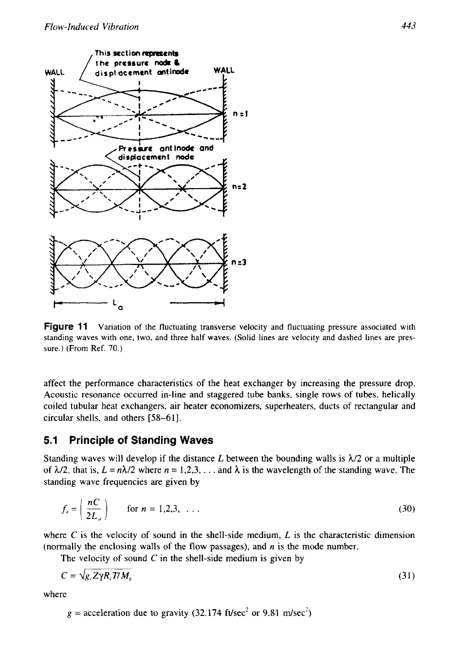
is associated with the standing waves (gas column). Standing waves (Fig.
11)
occur transverse
to both the tube axis and flow direction. The resonant vibration
of
the standing waves surround-
ing the tubes is commonly called acoustic resonance or acoustic vibration. It is usually charac-
terized with intense, low-frequency, pure-tone noise. When the excitation frequency is closer
to the standing wave frequency or both coincide in a heat exchanger, there is a possibility
of
acoustic vibration.
Also,
if the standing wave frequency coincides with natural frequencies
of
structural components such as casing, tubes, etc., it may be structurally harmful
[57]
and
it
can
-
DAMPING
PARAMETER
(””
PP’
)
Figure
10
Stability diagram.
Flow-
Induced
Vibration
443
This
section
men&
the
pressure
nodr
L
WALL
/
dirp~
accment antide
WeLL
I
,
Rerbt
ant Inode and
Figure
1
1
Variation of the fluctuating transverse velocity and fluctuating pressure associated with
standing waves with one, two, and three half waves. (Solid lines are velocity and dashed lines are pres-
sure.)
(From
Ref.
70.)
affect the performance characteristics of the heat exchanger by increasing the pressure drop.
Acoustic resonance occurred in-line and staggered tube banks, single
rows
of
tubes, helically
coiled tubular heat exchangers, air heater economizers, superheaters, ducts
of
rectangular and
circular shells, and others
[58-611.
5.1
Principle
of
Standing
Waves
Standing waves will develop if the distance
L
between the bounding walls is
h12
or a multiple
of h12, that is,
L
=
nh/2 where
n
=
1,2,3,
.
. .
and
h
is the wavelength of the standing wave. The
standing wave frequencies are given by
where
C
is the velocity of sound in the shell-side medium,
L
is the characteristic dimension
(normally the enclosing walls of the flow passages), and
n
is the mode number.
The velocity of sound
C
in the shell-side medium is given by
C
=
dg,ZyR,T/M,
where
g
=
acceleration due to gravity (32.174 ft/sec' or
9.81
&sec')