Kuppan T. Heat Exchanger Design Handbook
Подождите немного. Документ загружается.

404
Chapter
9
paraffin wax deposition during cooling of hydrocarbon streams. There are various remedies
for dealing with duties where solidification occurs on the product side:
1.
Do
not include very large fouling resistances in the design. This will result
in
an oversized
unit, which presents problems in the clean condition.
2.
Use concurrent flow instead of counterflow.
8
FOULING DATA
In choosing the fouling resistances to be used in a given heat exchanger, the designer has three
main sources
[
131:
1.
Past experience of heat exchanger performance in the same or similar environments.
2.
Results from portable test rigs.
3.
TEMA values, which are overall values for a very limited number of environments.
8.1
Instruments
for
Monitoring
of
Fouling
Instruments have been developed to monitor conditions on a tube surface to indicate accumula-
tion of fouling deposits and, in some cases, to indicate the effect on heat exchanger perfor-
mance. Various fouling monitors are described
in
Ref.
14.
The following is a summary of the
different fouling monitors
[
21.
1.
Removable sections of the fouled surface, which may be used for microscopic examina-
tion, mass measurements, and chemical and biological analysis
of
the deposits.
2.
Increase in pressure drop across the heat exchanger length. This method provides a mea-
sure
of
fluid frictional resistance, which usually increases with buildup of fouling deposits.
This device is relatively inexpensive and is easy to operate.
3.
Thermal resistance monitors, which are used to determine the effect of the deposit on
overall heat transfer resistance. The thermal method of monitoring has the advantage over
the others of giving directly information that is required for predicting or assessing heat-
transfer performance.
8.2
Gas-Side Fouling Measuring Devices
Marner and Henslee
[
151 carried out a comprehensive review of gas-side fouling measuring
devices. They classified the devices into the five groups: heat flux meters, mass accumulation
probes, optical devices, deposition probes, and acid condensation probes.
A
heat flux meter
uses the local heat transfer per unit area to monitor the fouling. The decrease in heat flux as
a
function of time is thus a measure of the fouling buildup. A mass accumulation device mea-
sures the fouling deposit under controlled conditions. Optical measuring devices use optical
method to determine the deposition rate. Acid condensation probes are used to collect liquid
acid that accumulates on a surface that is at a temperature below the acid dew point of the gas
stream.
9
HOW FOULING
IS
DEALT WHILE DESIGNING
HEAT EXCHANGERS
At present, fouling is usually treated in a very elementary way in design by this measure [16]:
adding an extra thermal resistance, known
as
fouling factors, or providing extra surface area
to accommodate fouling.
Fouling
405
9.1
Specifying the Fouling Resistances
Values of the fouling resistances are specified that are intended to reflect the values at the
point in time just before the exchanger is to be cleaned. This implies that the exchanger is
oversized for clean condition and barely adequate for conditions just before it should be
cleaned. The fouling resistances result in higher heat-transfer surface area. Planned fouling
prevention, maintenance, and cleaning can justify lower fouling resistances, but at higher ongo-
ing costs
[4].
9.2
Oversizing
Another approach to heat exchanger design is to arbitrarily increase the heat-transfer surface
area to allow for fouling. This approach usually assumes zero fouling resistance in the funda-
mental overall heat-transfer equation. The overall heat-transfer coefficient is determined for
clean conditions, and subsequently, the surface area required for clean condition is increased
by a certain percentage. Based upon experience, the oversurface specified can range from
15
to
50%
depending on the service
[4].
In effect, the fouling for the exchanger is combined and
no longer can be identified as belonging to one side or another.
10
TEMA FOULING RESISTANCE VALUES
The influence of the TEMA Fouling Resistance values
[
171
on design of heat exchangers has
been enormous. In practice some thought the TEMA values too high, others too low, since the
tendency to fouling in a heat exchanger is dependent upon parameters such as local flow
velocities, heat fluxes, etc., rather than overall values or point values as given for most cases
in
TEMA.
Fouling types and effects of fouling are included in the RGP section of the seventh
edition. The data contained in the new section are the results
of
studies by Heat Transfer
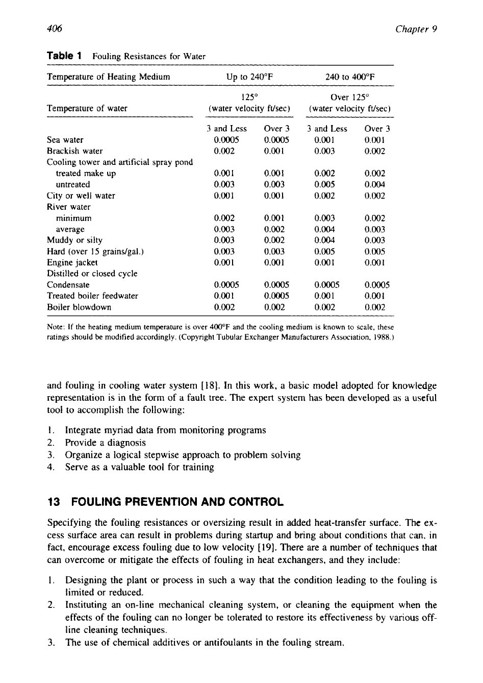
Research, Inc. (HTRI), and TEMA jointly for several years. TEMA fouling resistance values
for water are given in Table
1.
10.1
Research in Fouling
Much research is in underway for fouling. This research will some day enable us
to
understand
the parameters responsible for fouling and hence to devise means to control or eliminate foul-
ing. Today, however, we largely rely upon experience.
Important cooperative research is being done by groups such as Heat Transfer Research,
Inc. (USA), and the Heat Transfer and Fluid
Flow
Service (UK). By the year
2000,
it is likely
that a number of usable models will be available that are somewhat better than the TEMA
fouling resistances
[
161.
11
FOULING MONITORING
Exchangers subject to fouling or scaling should be monitored for their efficient functioning. A
light fouling on the tube greatly reduces its efficiency. A marked increase in pressure drop
and/or reduction in performance usually indicates fouling. The unit should first be checked for
air or vapor binding to confirm that this is not the cause for the reduction in performance.
12
EXPERT
SYSTEM
A computerized, consultative expert system has been developed that can simulate human rea-
soning, perform water treatment diagnoses, and recommend procedures to minimize corrosion
406
Chapter
9
Table
1
Fouling Resistances for Water
Temperature
of
Heating Medium
Up
to
240°F 240
to
400°F
125"
Over
125"
Temperature of water
(water velocity ft/sec)
(water velocity ft/sec)
3
and Less
Over
3
3
and Less
Over
3
Sea water
0.0005 0.0005 0.00
1
0.00
1
Brackish water
0.002
0.001 0.003
0.002
Cooling tower and artificial spray pond
treated
make
up
0.00
1
0.00
1
0.002
0.002
untreated
0.003 0.003
0.005
0.004
City or
well
water
0.001
0.00
1
0.002
0.002
River water
minimum
0.002
0.002
0.003
0.002
average
0.003
0.002
0.004
0.003
Muddy or silty
0.003
0.002 0.004
0.003
Hard (over
15
graindgal.)
0.003
0.003 0.005
0.005
Engine jacket
0.00
1
0.00
1
0.00
1
0.00
1
Distilled or closed cycle
Condensate
0.0005 0.0005 0.0005
0.0005
Treated boiler feedwater
0.00
1
0.0005
0.001
0.00
1
Boiler blowdown
0.002
0.002
0.002
0.002
Note:
If
the heating medium temperature is
over
400°F
and the cooling medium is known to scale, these
ratings should
be
modified accordingly. (Copyright Tubular Exchanger Manufacturers Association,
1988.)
and fouling in cooling water system [18]. In this work, a basic model adopted for knowledge
representation is in the form of a fault tree. The expert system has been developed as a useful
tool to accomplish the following:
1.
Integrate myriad data from monitoring programs
2.
Provide a diagnosis
3.
Organize a logical stepwise approach to problem solving
4.
Serve as a valuable tool for training
13
FOULING PREVENTION AND CONTROL
Specifying the fouling resistances or oversizing result in added heat-transfer surface. The ex-
cess surface area can result in problems during startup and bring about conditions that
can,
in
fact, encourage excess fouling due
to
low velocity
[
191. There are
a
number of techniques that
can overcome or mitigate the effects of fouling in heat exchangers, and they include:
1.
Designing
the
plant or process in such a way that the condition leading to the fouling is
limited or reduced.
2.
Instituting an on-line mechanical cleaning system, or cleaning the equipment when the
effects of the fouling can no longer be tolerated to restore its effectiveness by various
off-
line cleaning techniques.
3.
The use of chemical additives or antifoulants in the fouling stream.
Fouling
407
These aspects are discussed in detail next.
13.1
Measures
to
Be
Taken During the Design Stages
No
hard and fast rules can be applied for heat exchanger design in relation to fouling, but the
following points should be kept in mind during the conception and design of a heat exchanger:
1.
Make the design simple.
2.
Select the heat exchanger type with point
1
in mind. Heat exchangers other than shell
and tube units may be better suited to fouling applications. Gasketed plate exchangers
and spiral plate exchangers offer better resistance to fouling because of increased turbu-
lence, higher shear, or other factors. Before commissioning a heat exchanger, carry out
design checks and ensure that all constructional details and clearances conform to specifi-
cation.
3.
Prevent the possibility of corrosion and fouling during and subsequent to hydrostatic
testing.
4.
Startup conditions should avoid temperatures higher or velocities lower than the design
values [3].
5.
Maximize the flow velocities of process fluids to enhance the removal of the fouling
deposits, provided that the fluid velocity is not high enough to cause excessive pressure
drop or flow-induced vibration on the shell side. Ensure that velocities in tubes are in
general above
2
m/s and about 1 m/s on the shell side [3]. Avoid stagnant areas where
the flow velocities are less than those in the bulk of the core.
6.
Assume nominal fouling resistance either from past experience or from published stan-
dards and design the heat exchanger with nominal oversizing. The oversizing may be of
the order of
2040%.
It is generally prudent to avoid large fouling factors, which result
in larger equipment. Larger equipment generally results
in
lower velocities and hence
may accelerate fouling.
7.
To minimize fouling of finned tube or plate fin heat exchangers, use optimum fin density.
Otherwise the initial benefit of increased heat transfer will be offset by fouling in the
long
run.
This is most appropriate for industrial air coolers, radiators of automobiles, and
diesel locomotives. Compact heat exchangers functioning in outdoor unit are most prone
to fouling due to airborne dirt, flying objects, leaves, and fibrous objects. Other considera-
tions are in-line layouts to provide cleaning lanes for soot blowers, and wide pitches for
dirty flue gases.
8.
Fouling fluid on the tube side: When the fouling fluid is on the tube side, Mukherjee [6]
recommends measures such as
(1)
using larger diameter tubes (a minimum of
25
mm
OD),
(2)
maintaining high velocity (for cooling water, a minimum velocity of
1.5
m/s
for mild steel,
1.2
m/s for nonferrous tubes, and as high as
5
m/s for titanium tubes is
recommended), (3) leaving sufficient margin in pressure drop (for high fouling services,
leave a margin of
3040%
between the allowable and calculated pressure drop),
(4)
using
a spare tube bundle or spare exchanger,
(5)
using two shells in parallel (each with 60-
70%
of total capacity), (6) using wire-fin tube inserts, and
(7)
using on-line cleaning
methods.
9.
Fouling fluid on the shell side: When the fouling fluid
is
on the shell side, use a square
or rotated square tube layout, minimize dead spaces by optimum baffle design, and main-
tain high velocity [6].
10.
If severe fouling is inevitable, it is frequently better to install spare units. Installed spares
will permit cleaning while the other unit is in service.
11.
Proper selection of cooling medium can frequently avoid problems associated with foul-
408
Chapter
9
ing. For example, air cooling in place of cooling water solves many of the corrosion
and
fouling problems such as scaling, biological growth, and many of the aqueous corrosion.
The cleaning of bare tube or finned tube surfaces fouled by air is easier than surfaces
fouled by water.
12.
Particulate fouling, scaling, and trace-metal-catalyzed hydrocarbon reaction fouling can
often be prevented by pretreatment of the feed streams to a heat exchanger by filtration,
softening, and desalting, respectively
[20].
13.
Once the unit is onstream, operate at the design conditions of velocity and temperature.
14
CLEANING
OF
HEAT EXCHANGERS
In most applications, fouling is known to occur in spite
of
good design, effective operation,
and maintenance. Hence, heat exchangers and associated equipment must be cleaned. The time
between cleaning operations will depend upon the severity of the fouling problem. In some
instances, cleaning can be carried out during periodical maintenance programs-say, twice
yearly or annually-but in other cases frequent cleaning will be required, perhaps as frequently
as monthly or quarterly. For example, locomotive radiators are air blown during their
fort-
nightly schedules.
14.1 Cleaning Techniques
In general, the techniques used to remove the foulants from the heat exchanger surfaces, both
on the shell side and on the tube side, can
be
broadly classified into two categories: mechanical
and chemical. The cleaning process may be employed while the plant is still operating, that is,
on line,
but in most situations it will be necessary to shutdown the plant to clean the heat
exchangers, known as
08-line
cleaning.
In
some instances combinations of these cleaning
methods may be necessary. Each method of cleaning has advantages and disadvantages with
specific equipment types and materials of construction.
14.2
Deposit Analysis
Information about the composition of fouling deposits through deposit analysis is extremely
helpful to identify the source of the major foulants, to develop proper treatment, and as an aid
in developing a cleaning method for a fouling control program
[5].
The sample should represent
the most critical fouling area. For heat exchangers and boilers,
this
is the highest heat transfer
area
[21].
Many analytical techniques are used to characterize deposit analysis. Typical meth-
ods include x-ray diffraction analysis, x-ray spectrometry, and optical emission spectroscopy.
14.3
Selection of Appropriate Cleaning Methods
Before attempting to clean a heat exchanger, the need should be carefully examined. Consider
the following factors for selecting a cleaning method:
Degree of fouling.
Nature of the foulant, known through deposit analysis.
Chemical cleaning is associated with pumping hot corrosives through temporary connections
and therefore the compatibility of the heat exchanger material and system components in
contact with the cleaning chemicals.
Regulations against environmental discharges.
Accessability
of
the surfaces for cleaning.
Cost factors.
Fouling
409
Precautions to Be Taken While Undertaking a Cleaning Operation
Precautions to be taken while undertaking a cleaning operation are listed in TEMA
[
171
para-
graph
E-4.32
and in Ref.
21:
1.
Individual tubes should not be steam blown because this heats the tube and may result in
severe thermal strain and deformation of the tube, or loosening of the tube to tube sheet
joint.
2.
When mechanically cleaning a tube bundle, care should be exercised to avoid damaging
the tubes. Tubes should not
be
hammered with a metallic tool.
Various cleaning methods are discussed next.
14.4
Off-Line Mechanical Cleaning
Techniques using mechanical means for the removal of deposits are common throughout the
industry. The various off-line mechanical cleaning methods are
1.
Manual cleaning
2.
Jet cleaning
3.
Drilling and roding of tubes
4.
Blasting
5.
Soot blowing
6.
Thermal cleaning
Manual Cleaning
Where there is good access, as with a plate or spiral heat exchanger, or a removable tube
bundle, and the deposit is soft, hand scrubbing and washing may be employed, although the
labor costs are high.
Jet Cleaning
Jet cleaning or hydraulic cleaning with high-pressure water jets can be used mostly on external
surfaces where there is an easy accessability for passing the high pressure jet. Jet washing can
be
used to clean foulants such as
[22]:
(1)
airborne contaminants of air-cooled exchangers at
a pressure of
2-4
bar,
(2)
soft deposits, mud, loose rust, and biological growths in shell and
tube exchangers at a pressure of
40-120
bar,
(3)
heavy organic deposits, polymers, tars in
condensers and other heat exchangers at
a
pressure of
300-400
bar, and
(4)
scales on the tube
side and fire side of boilers, preheaters, and economizers at a pressure of
300-700
bar. This
method consists of directing powerful water jets at fouled surfaces through special guns or
lances.
A
variety of nozzles and tips is used to make most effective use of the hydraulic force.
The effectiveness of this cleaning procedure depends on accessibility, and care is needed in
application to prevent damage to the tubes and injury to the personnel. Similar to water jet
cleaning, pneumatic descaling is employed on the fire side of coal-fired boiler tubes.
Drilling and Roding
of
Tubes
Drilling is employed for tightly plugged tubes and roding for lightly plugged tubes. Drilling
of tightly plugged tubes is known as bulleting. For removing deposits, good access is required,
and care is again required to prevent damage to the equipment.
A
typical example is roding of
radiator tubes plugged by solder bloom corrosion products.
Turbining
Turbining is a tube-side cleaning method that uses
air,
steam, or water to send motor-driven
cutters, brushes, or knockers in order to remove deposits.
410
Chapter
9
Blast Cleaning
Blast cleaning involves propelling suitable abrasive material at high velocity by a blast of
air
or water (hydroblasting)
to
impinge on the fouled surface. Hydroblasting is seldom used
to
clean tube bundles because the tubes are very thin. However, the technique is suitable
to
descale and clean tube-sheet faces, shells, channel covers, bonnets, and return covers inside
and outside.
Soot Blowing
Soot blowing is a technique employed for boiler plants, and the combustion or flue gas heat
exchangers of fired equipment. The removal of particles is achieved by the use of air or steam
blasts directed on the fin side. Water washing may also be used to remove carbonaceous
deposits from boiler plants.
A
similar cleaning procedure is followed for air blowing of radia-
tors on the fin side during periodical schedule attention.
Thermal Cleaning
Thermal cleaning involves steam cleaning, with or without chemicals. This method is also
known as hydrosteaming. It can be used to clean waxes and greases
in
condensers and other
heat exchangers.
14.5 Merits
of
Mechanical Cleaning
The merits of mechanical cleaning methods include simplicity and ease of operation, and capa-
bility to clean even completely blocked tubes. However, this method may damage the equip-
ment, particularly tubes, it does not produce a chemically clean surface, and the use of high
pressure water jet or air jet may cause injury and/or accidents to personnel engaged in the
cleaning operation-hence the personnel are to be well protected against injuries.
14.6 Chemical Cleaning
The usual practice is to resort to chemical cleaning of heat exchangers only when other meth-
ods are not satisfactory. Chemical cleaning involves the use of chemicals to dissolve or loosen
deposits. The chemical cleaning methods are mostly off-line.
Choosing a Chemical Cleaning Method
Chemical cleaning methods must take into account a number
of
factors such as:
1.
Compatibility of the system components with the chemical cleaning solutions. If required,
inhibitors are added to the cleaning solutions.
2.
Information relating to the deposit must be known beforehand.
3.
Chemical cleaning solvents must be assessed by a corrosion test before beginning cleaning
operation.
4.
Adequate protection of personnel employed in the cleaning of the equipment must be
provided.
5.
Chemical cleaning poses the real possibility of equipment damage from corrosion. Precau-
tions may be taken to reduce the corrosion rate to acceptable levels. On-line corrosion
monitoring during cleaning is necessary
[2
11.
Postcleaning inspection is extremely impor-
tant to check for corrosion damage due to cleaning solvents and to gauge the cleaning
effectiveness.
6.
Disposal of the spent solution.
Chemical Cleaning Solutions
Chemical cleaning solutions include mineral acids, organic acids, alkaline bases, complexing
agents, oxidizing agents, reducing agents, and organic solvents. Inhibitors and surfactant are
Fou
1
ing
41
I
Table
2
Foulants and Common Solvents
[22]
Foulant Cleaning solvent
Iron oxides
Inhibited hydrofluoric acid, hydrochloric acid, monoammoniated cit-
ric acid or sulfamic acid, EDTA
Calcium and magnesium scale
Inhibited hydrochloric acid, citric acid, EDTA
Oils or light greases
Sodium hydroxide, trisodium phosphate with or without detergents,
water-oil emulsion
Heavy organic deposits such as
Chlorinated or aromatic solvents followed by a thorough rinsing
tars, asphalts, polymers
Coke/carbonaceous deposits
Alkaline solutions of potassium permanganate or steam air de-
coking
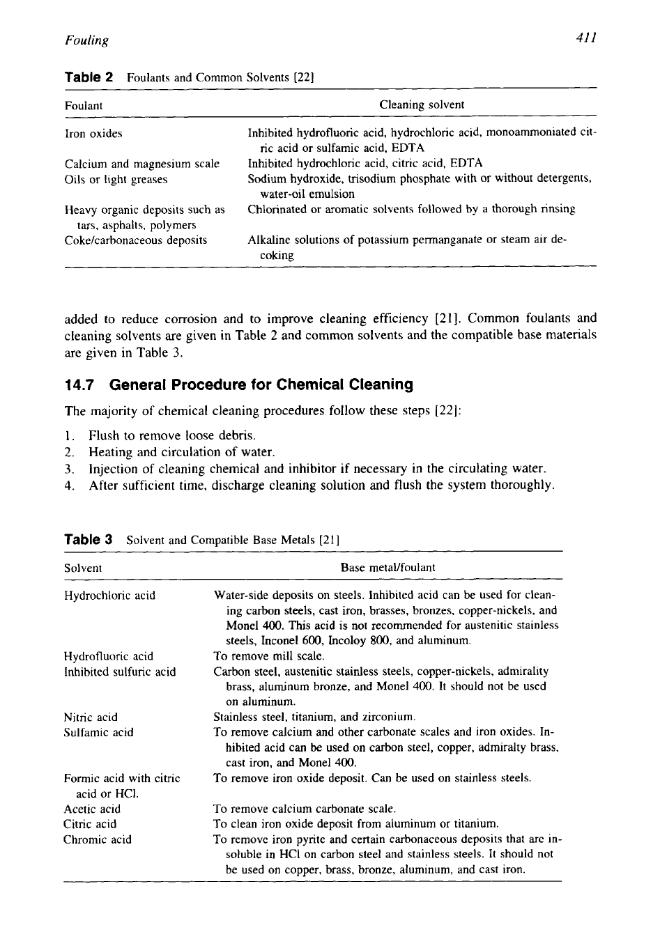
added to reduce corrosion and to improve cleaning efficiency [21]. Common foulants and
cleaning solvents are given in Table 2 and common solvents and the compatible base materials
are given in Table
3.
14.7 General Procedure
for
Chemical Cleaning
The majority
of
chemical cleaning procedures follow these steps
[22]:
1.
Flush to remove loose debris.
2.
Heating and circulation of water.
3.
Injection of cleaning chemical and inhibitor if necessary in the circulating water.
4.
After sufficient time, discharge cleaning solution and
flush
the system thoroughly.
Table
3
Solvent and Compatible Base Metals
[21]
~~
Solvent Base metaVfoulant
Hydrochloric acid
Water-side deposits on steels. Inhibited acid can be used for clean-
ing carbon steels, cast iron, brasses, bronzes, copper-nickels, and
Monel
400.
This acid is not recommended for austenitic stainless
steels, Inconel600, Incoloy
800,
and aluminum.
Hydrofluoric acid
To
remove mill scale.
Inhibited sulfuric acid Carbon steel, austenitic stainless steels, copper-nickels, admirality
brass, aluminum bronze, and Monel
400.
It should not be used
on aluminum.
Nitric acid
Stainless steel, titanium, and zirconium.
Sulfamic acid
To
remove calcium and other carbonate scales and iron oxides. In-
hibited acid can be used on carbon steel, copper, admiralty brass,
cast iron, and Monel400.
Formic acid with citric
To
remove iron oxide deposit. Can be used on stainless steels.
acid or HCl.
Acetic acid
To
remove calcium carbonate scale.
Citric acid
To
clean iron oxide deposit from aluminum or titanium.
Chromic acid
To
remove iron pyrite and certain carbonaceous deposits that are in-
soluble in HC1 on carbon steel and stainless steels. It should not
be used on copper, brass, bronze, aluminum, and cast iron.
412
Chapter
9
5.
Passivate the metal surfaces.
6.
Flush to remove all traces of cleaning chemicals.
It is suggested that one employ qualified personnel or a qualified organization for cleaning
services.
14.8
Off-Line Chemical Cleaning
Major off-line chemical cleaning methods are
1.
Circulation
2.
Acid cleaning
3.
Fill and
soak
cleaning
4.
Vapor-phase organic cleaning
5.
Steam injection cleaning
Circulation.
This method involves the filling of the equipment with cleaning solution
and
circulating it by a pump. While cleaning is in progress, the concentration and temperature
of
the solution are monitored.
Acid Cleaning.
Scales due to cooling water are removed by circulating a dilute hydrochloric
acid solution. This is discussed in detail with the discussion of cooling-water fouling.
Fill
and Soak Cleaning.
In this method, the equipment is filled with a chemical cleaning
solution and drained after a period of time. This may
be
repeated several times until satisfactory
results are achieved. However, this method is limited to small units only.
Vapor-Phase Organic Cleaning.
This method is used to remove deposits that are organic in
nature.
Steam Injection Cleaning.
This method involves an injection of a concentrated mix of clean-
ing solution and steam into a fast-moving stream. The steam atomizes the chemicals, increasing
their effectiveness and ensuring good contact with metal surfaces.
14.9
Merits
of
Chemical Cleaning
Chemical cleaning offers the following advantages over the mechanical cleaning:
1. Uniform cleaning and sometimes complete cleaning.
2.
Sometimes chemical cleaning is the only possible method.
3.
No
need to dismantle the unit, but it must be isolated from the system.
4.
Capable of cleaning inaccessible areas.
5.
Moderate cleaning cost and longer intervals between cleaning.
14.1
0
Disadvantages
of
Chemical Cleaning Methods
Chemicals used for cleaning are often hazardous to use and require elaborate disposal proce-
dures. Noxious gases can be emitted from the cleaning solution from unexpected reactions.
Chemical cleaning corrodes the base metal and the possibility of excess corrosion cannot be
ruled out. Complete washing of the equipment is a must
to
eliminate corrosion due to residual
chemicals.
14.1
1
On-Line Cleaning Methods
There is an obvious need for an industrial on-line cleaning procedure that can remove fouling
deposits without interfering with a plant’s normal operation. On-line cleaning methods can be
Fouling
413
either mechanical or chemical. On-line chemical cleaning is normally achieved by dosing with
chemical additives.
14.12
On-Line Mechanical Cleaning Methods
Various on-line mechanical cleaning methods to control fouling
in
practice are:
1.
Upstream filtration
2.
Flow excursion
3.
Air bumping
of
heat exchangers
4.
Reversing flow in heat exchangers
5.
Passing brushes through exchanger tubes
6.
Sponge rubber balls cleaning system
7.
Brush and cage system
8.
SPIRELF system
9.
Grit cleaning
10.
Use of inserts
11.
Self-cleaning fluidized-bed exchangers
Upstream Filtration (Debris Filter)
Cooling-water fouling can be controlled, and in some cases eliminated, by adequately filtering
the intake water. Power-station condensers are more vulnerable to the intake of debris and
biological organisms. One solution to prevent the blockage
of
condenser tubes is the installa-
tion of an upstream filtration system. All particles in the cooling water larger than 10 mm are
kept in the filter and rinsed away through the debris discharge
[23].
Flow Excursion
In this method the instantaneous flow is increased to remove the fouling deposits. This method
is particularly applicable to a heat exchanger fouled badly due to the effects of low velocity
either on the shell side or the tube side.
Air Bumping
This technique involves the creation
of
slugs
of
air, thereby creating localized turbulence as
slugs pass through the equipment. The technique has been applied to the liquid system
on
the
shell side of heat exchangers. Care has to be taken to avoid the possibility of producing explo-
sive mixtures of gases if the process fluid is volatile and flammable
[3].
Reversing Flow in Heat Exchangers
This is followed on the water side of the cooling-water system by intermittent reversal of flow
and intermittent air injection.
Passing Brushes Through Exchanger Tubes
CTI developed the ram brush to clean fouled heat exchanger tubes
[
161. The unit consists
of
a
2.5-in-long plastic dowel wrapped with 1.5-in nylon bristles. The brushes are propelled through
the tube by an air and water gun and shot right through the tube. Water pressure of 40-60 psi
and air pressure
of
90-100
psi are sufficient to send the ram brush through standard heat
exchanger tubes.
Sponge Rubber Ball Cleaning System
A
large number of sponge rubber balls, slightly larger in diameter than the inner diameter
of
the tubes and having about the same specific gravity as sea water, are passed continuously into
the inlet water box as shown in Fig.
6
(for instance, the Taprogge system)
[23].
The cooling-