Kuppan T. Heat Exchanger Design Handbook
Подождите немного. Документ загружается.

444
Chapter
I0
Z
=
gas compressibility factor
R,
=
universal gas constant, 1545.32 lbf ft/lb mole or 847.6 kgf m/kg mole
OK
T=
absolute temperature
of
the gas,
"W"K
=
"F
+
459.69"F or
"C
+
273.16
M,
=
molecular weight of the gas, lb mole or
kg
mole
y=
ratio
of
specific heat of gas at constant pressure to constant volume
The value
of
MK
(molecular weight of the gas)
for
air or flue gas is 28.97 lb mole and for
steam 18.02 lb mole, and
y,
the ratio of the specific heat of the gas at constant pressure to that
at constant volume, is 1.4 for air or flue gas and 1.328 for steam [62].
Typical standing waves with fundamental, second, and third modes are shown in Fig. 11.
Normally the standing wave will form in open lanes of
45"
or 90" layout angle geometries,
since the least exciting energy is required to form in these tube layout patterns. According
to
Barrington [63], acoustic vibration occurs most frequently with a rotated square (45') tube
layout compared to other tube layouts. Although the rotated square geometry exhibited
the
greatest resistance to
FEI,
this was marred by the presence of intense acoustic standing waves.
Hence they may not be suitable for shell-side gaseous medium [40].
Effect of Tube Solidity on Sound Velocity
For shell and tube heat exchangers, Parker [64] and Burton [65] have shown that the actual
speed of sound
C
in the shell-side fluid is reduced due to the presence of the tubes. The rate
of decrease of the sound speed is mainly dependent on the solidity ratio
0
of the tube layout
and a weak function of added mass coefficient,
C,.
Accordingly, formulas for effective speed
of sound
Cef,
through the tube bundle are given by
L
Burton
For widely spaced arrays
C,
=
1
(approximately).
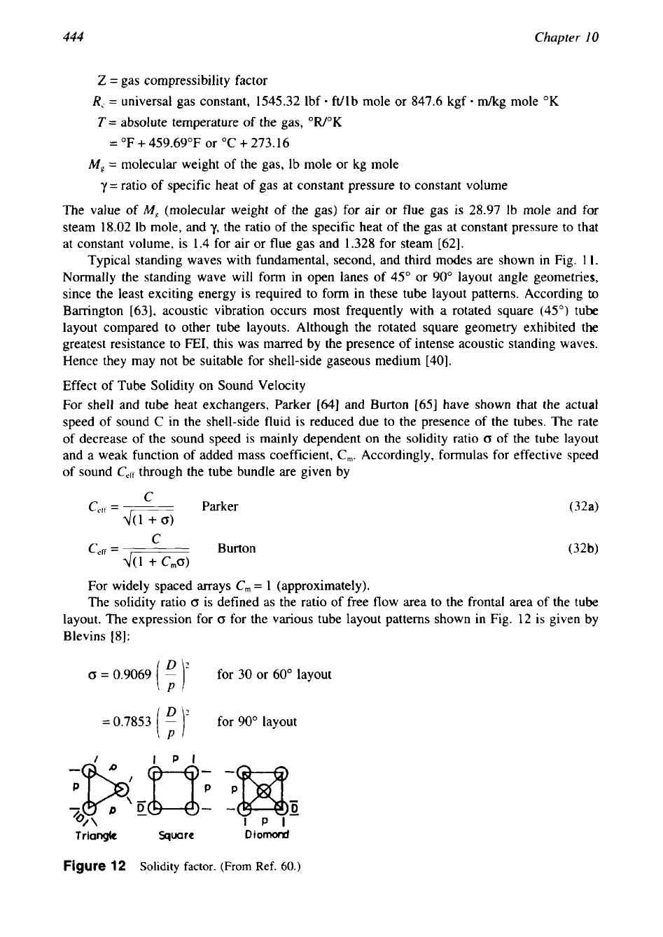
The solidity ratio
0
is
defined as the ratio of free flow area to the frontal area of the tube
layout. The expression for
0
for the various tube layout patterns shown in Fig. 12 is given by
Blevins [8]:
0
=
0.9069
for
30
or 60" layout
D
=
0.7853
[
;
1'
for 90" layout
triangk
Square
Diomord
Figure
12
Solidity
factor.
(From
Ref.
60.)
445
Flow-
Induced Vibration
D
=
1.5707
[
p
)?
for 45" layout
(33)
In heat exchangers of normal size, either the fundamental mode or the second mode is
most likely to occur. However, in large exchangers with shell diameter of the order of
20-30
m the acoustic vibration can be excited up to fifth or sixth mode.
Principles of acoustic vibration, their evaluation, and prediction methods are discussed by
Grotz and Arnold [66], in refs. 24, 25, and 57-62, by Barrington [63,67], and by Fitzpatrick
[68]. The better understanding of acoustic resonance is mostly due to Dr. Blevins. In this
section, the excitation mechanisms are discussed and acceptance criteria are defined.
5.2
Expressions
for
Acoustic Resonance Frequency
Two versions of expression, one in terms of shell-side pressure and shell-side fluid density
(TEMA) and the other in terms velocity of sound through shell-side medium and shell dimen-
sions, are given next for calculating the acoustic vibration frequency
h.
TEMA Expression
483.2
p,
0s
fa=-(
(use TEMA dimensional units)
(34)
L
0
---I
Blevins Expression
Circular Shell.
For
a circular shell of radius
R,
the expression for standing wave frequency
is given by [8,62]:
where
h,
=
1.84 and
h2
=
3.054.
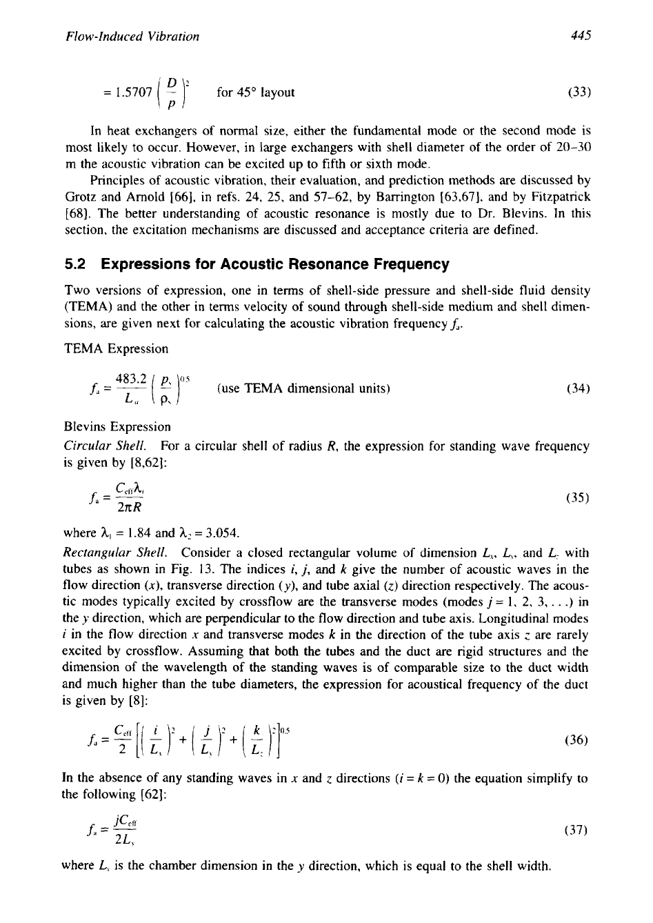
Rectangular Shell.
Consider a closed rectangular volume
of
dimension
L,,
L,,
and
L:
with
tubes as shown in Fig. 13. The indices
i,
j,
and
k
give the number of acoustic waves in the
flow direction
(x),
transverse direction
(y),
and tube axial
(z)
direction respectively. The acous-
tic modes typically excited by crossflow are the transverse modes (modes
j
=
1, 2, 3,
.
.
.)
in
the
y
direction, which are perpendicular to the flow direction and tube axis. Longitudinal modes
i
in the flow direction
x
and transverse modes
k
in the direction of the tube axis
c'
are rarely
excited by crossflow. Assuming that both the tubes and the duct are rigid structures and the
dimension of the wavelength of the standing waves is of comparable size to the duct width
and much higher than the tube diameters, the expression for acoustical frequency of the duct
is given by [8]:
In the absence of any standing waves in
x
and
z
directions
(i
=
k
=
0)
the equation simplify to
the following [62]:
where
L,
is the chamber dimension in the
y
direction, which is equal to the shell width.
446
Chapter
10
Figure
13
Acoustic modes in a closed rectangular chamber with tubes. (a) Tube bundle in duct;
(b)
typical mode shape of pressure
in
cutoff mode. (From Ref.
60.)
5.3
Excitation Mechanisms
The occurrence of acoustic resonance in tubular heat exchangers is caused by either a vortex
shedding mechanism or turbulent buffeting.
Vortex Shedding Mechanism
According to vortex shedding theory, if the frequency of vortex shedding coincides with the
standing wave frequency, a strong acoustic oscillation of the gas column is possible and reso-
nance is said to occur. Thus the resonance criterion is
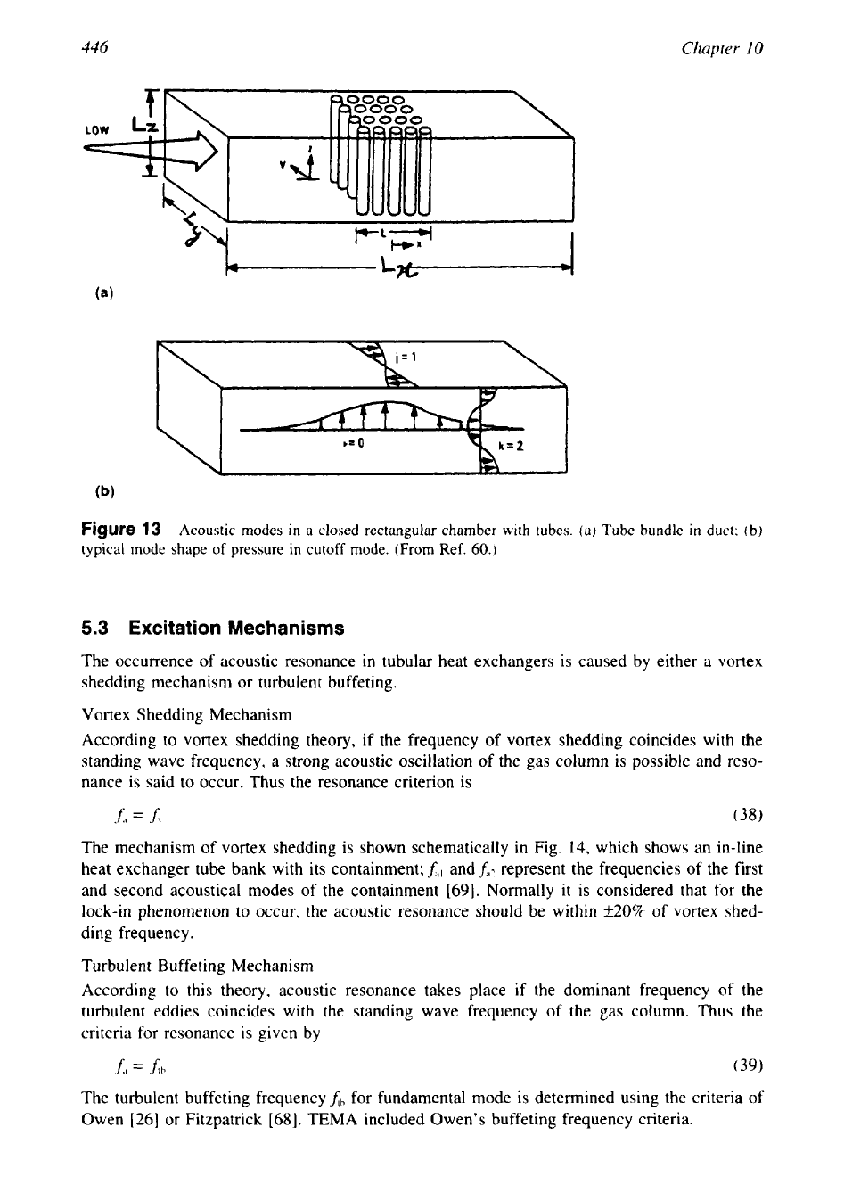
The mechanism of vortex shedding is shown schematically in Fig.
14,
which shows an in-line
heat exchanger tube bank with its containment;
h,
and
fd2
represent the frequencies of the first
and second acoustical modes of the containment
[69].
Normally it
is
considered that for the
lock-in phenomenon to occur, the acoustic resonance should be within
k20%
of vortex shed-
ding frequency.
Turbulent Buffeting Mechanism
According to this theory, acoustic resonance takes place
if
the dominant frequency of the
turbulent eddies coincides with the standing wave frequency of the gas column. Thus the
criteria for resonance is given by
JI
=
Ah
(39)
The turbulent buffeting frequency
$h
for fundamental mode is determined using the criteria of
Owen
[26]
or Fitzpatrick
[68].
TEMA included Owen’s buffeting frequency criteria.
447
Flow-Induced Vibration
Figure
14
Acoustic resonance due to vortex shedding.
5.4
Acceptance Criteria
for
Occurrence
of
Acoustic Resonance
Vortex Shedding
Eisinger criterion
[25,57].
Eisinger expressed a criterion in terms
of
the Chen number,
w,
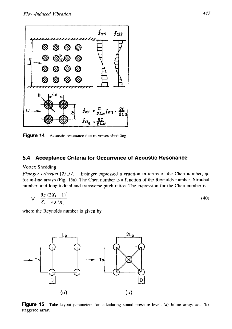
for in-line arrays (Fig. 15a). The Chen number
is
a function of the Reynolds number, Strouhal
number, and longitudinal and transverse pitch ratios. The expression for the Chen number
is
w=--
Re
(2XI
-
1)'
S"
4XfX,
(40)
where the Reynolds number is given by
Figure
15
Tube layout parameters for calculating sound pressure level.
(a)
Inline array; and (b)
staggered may.
448
Chapter
10
UD
Re=-
(41)
1’
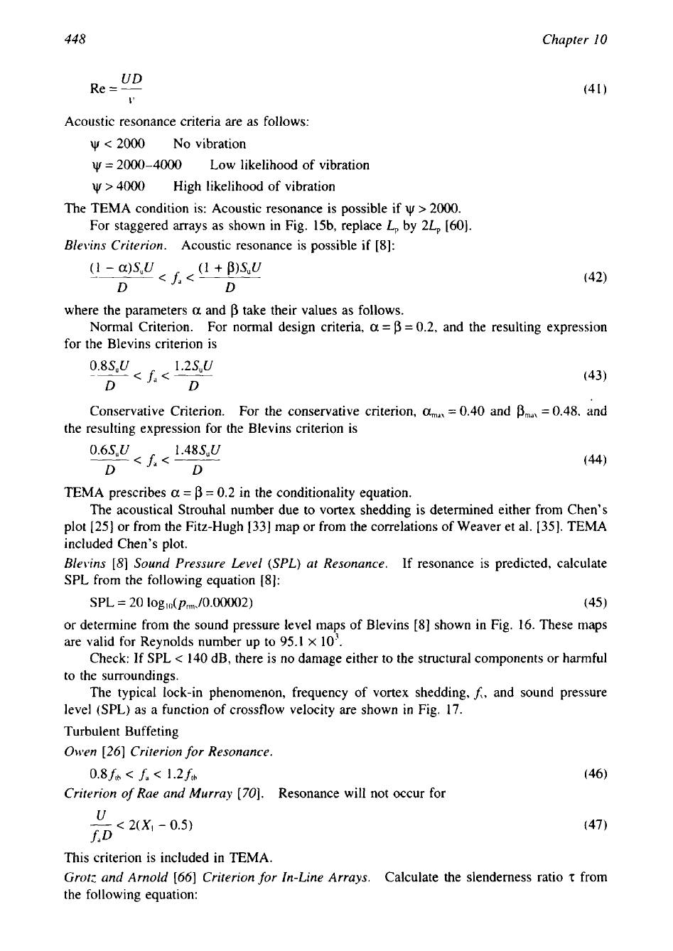
Acoustic resonance criteria are as follows:
<
2000
No vibration
w
=
2000-4000 Low likelihood
of vibration
w
>
4000
High likelihood of vibration
The TEMA condition is: Acoustic resonance is possible if
w
>
2000.
For staggered arrays as shown in Fig. 15b, replace
L,
by
24
[60].
Blevins Criterion.
Acoustic resonance is possible if
[8]:
where the parameters
a
and
p
take their values as follows.
Normal Criterion.
For normal design criteria,
a
=
p
=
0.2, and the resulting expression
for the Blevins criterion is
0.8SuU
1
.2suu
D
<fa<--
D
(43)
=
0.40
and
Pmax
Conservative Criterion. For the conservative criterion,
amay
=
0.48,
and
the resulting expression for the Blevins criterion is
0.6SuU
1
.48SuU
<fa<---
D
D
TEMA prescribes
a
=
p
=
0.2
in the conditionality equation.
The acoustical Strouhal number due to vortex shedding is determined either from Chen’s
plot [25] or from the Fitz-Hugh [33] map or from the correlations of Weaver et al. [35]. TEMA
included Chen’s plot.
Blevins
[8]
Sound Pressure Level (SPL) at Resonance.
If resonance is predicted, calculate
SPL from the following equation
[8]:
SPL
=
20
10g,,(p,,,/0.00002) (45)
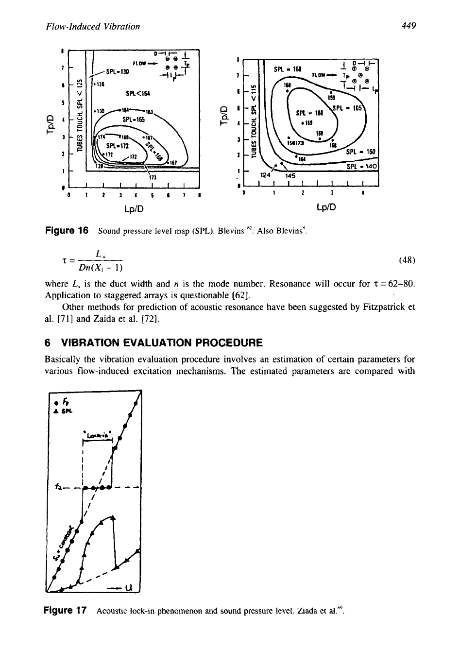
or
determine from the sound pressure level maps of Blevins
[8]
shown in Fig.
16.
These maps
are valid for Reynolds number up to
95.1
x
103.
Check: If SPL
<
140 dB, there
is
no damage either to the structural components or harmful
to the surroundings.
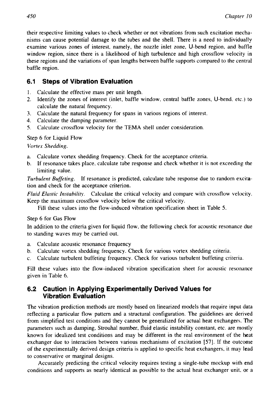
The typical lock-in phenomenon, frequency of vortex shedding,
J,
and sound pressure
level (SPL) as a function of crossflow velocity are shown in Fig. 17.
Turbulent Buffeting
Otven
[26]
Criterion
for
Resonance.
Criterion
of
Rue and Murray
[70].
Resonance will not occur for
This criterion
is
included in TEMA.
Grotz and Arnold
[66]
Criterion for In-Line Arrays.
Calculate the slenderness ratio
‘z:
from
the following equation:
449
Flow-Induced Vibration
171
0
n
0
I 2
3 4 5 6 7 1
Lp/D
Lp/D
Figure
16
Sound pressure level map
(SPL).
Blevins
62.
Also Blevins'.
La
2=
Dn(X1
-
1)
where
L,,
is the duct width and
n
is the mode number. Resonance will occur for
z
=
62-80.
Application to staggered arrays is questionable [62].
Other methods
for
prediction
of
acoustic resonance have been suggested by Fitzpatrick et
al.
[71]
and Zaida et al.
[72].
6
VIBRATION EVALUATION PROCEDURE
Basically the vibration evaluation procedure involves
an
estimation of certain parameters for
various flow-induced excitation mechanisms. The estimated parameters are compared with
Figure
17
Acoustic lock-in phenomenon and sound pressure level. Ziada et al.69.
450
Chapter
I0
their respective limiting values to check whether or not vibrations from such excitation mecha-
nisms can cause potential damage to the tubes and the shell. There is a need to individually
examine various zones of interest, namely, the nozzle inlet zone, U-bend region, and baffle
window region, since there is a likelihood of high turbulence and high crossflow velocity
in
these regions and the variations of span lengths between baffle supports compared to the central
baffle region.
6.1
Steps
of
Vibration Evaluation
1.
Calculate the effective mass per unit length.
2.
Identify the zones
of
interest (inlet, baffle window, central baffle zones, U-bend, etc.) to
calculate the natural frequency.
3.
Calculate the natural frequency for spans in various regions of interest.
4. Calculate the damping parameter.
5.
Calculate crossflow velocity for the
TEMA
shell under consideration.
Step
6
for Liquid Flow
Vortex Shedding.
a.
Calculate vortex shedding frequency. Check for the acceptance criteria.
b.
If resonance takes place, calculate tube response and check whether it is not exceeding the
limiting value.
Turbulent Buffeting.
If resonance is predicted, calculate tube response due to random excita-
tion and check for the acceptance criterion.
Fluid Elastic Instability.
Calculate the critical velocity and compare with crossflow velocity.
Keep the maximum crossflow velocity below the critical velocity.
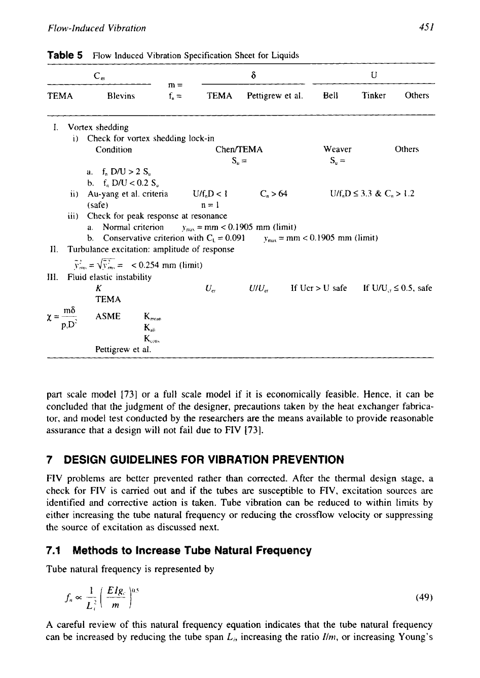
Fill these values into the flow-induced vibration specification sheet in Table
5.
Step
6
for Gas Flow
In addition to the criteria given for liquid flow, the following check for acoustic resonance due
to standing waves may be carried out.
a. Calculate acoustic resonance frequency
b. Calculate vortex shedding frequency. Check for various vortex shedding criteria.
c. Calculate turbulent buffeting frequency. Check for various turbulent buffeting criteria.
Fill these values into the flow-induced vibration specification sheet for acoustic resonance
given in Table
6.
6.2
Caution in Applying Experimentally Derived Values for
Vibration Evaluation
The vibration prediction methods are mostly based on linearized models that require input data
reflecting a particular flow pattern and a structural configuration. The guidelines are derived
from simplified test conditions and they cannot be generalized for actual heat exchangers. The
parameters such as damping, Strouhal number, fluid elastic instability constant, etc. are mostly
known for idealized test conditions and may be different in the real environment of the heat
exchanger due to interaction between various mechanisms of excitation
[57].
If the outcome
of the experimentally derived design criteria is applied to specific heat exchangers, it may lead
to conservative or marginal designs.
Accurately predicting the critical velocity requires testing a single-tube mockup with end
conditions and supports as nearly identical as possible to the actual heat exchanger unit, or a
451
Flow-Induced
Vibration
Table
5
Flow Induced Vibration Specification Sheet for Liquids
cm
6
U
m=
TEMA Blevins
f,
=
TEMA Pettigrew et al. Bell Tinker Others
I. Vortex shedding
i)
Check for vortex shedding lock-in
Condition CheflEMA Weaver Others
S"
=
s,
=
a.
f,
D/U
>2
S,
b.
f,, D/U
c
0.2
S,
ii) Au-yang et al. criteria
U/f,D
<
1 C,
>
64
U/f,D
53.3
&
C,
>
1.2
(safe) n=l
iii) Check for peak response at resonance
a. Normal criterion
ymdk
=
mm
<
0.1905
mm
(limit)
=
mm
<
0.1905
mm
(limit)
b. Conservative criterion with CL
=
0.091
ymaX
11. Turbulance excitation: amplitude of response
y;,,,,
=
a
=
<
0.254
mm (limit)
111. Fluid elastic instability
K
uer
UlU,,
If Ucr
>
U safe
If
U/UCr
50.5,
safe
TEMA
Km,
Pettigrew et al.
part scale model
[73]
or a full scale model if it is economically feasible. Hence, it can be
concluded that the judgment of the designer, precautions taken by the heat exchanger fabrica-
tor, and model test conducted by the researchers are the means available to provide reasonable
assurance that a design will not fail due to FIV
[73].
7
DESIGN GUIDELINES
FOR
VIBRATION PREVENTION
FIV problems are better prevented rather than corrected. After the thermal design stage, a
check for FIV is carried out and if the tubes are susceptible to FIV, excitation sources are
identified and corrective action is taken. Tube vibration can be reduced to within limits by
either increasing the tube natural frequency or reducing the crossflow velocity or suppressing
the source of excitation as discussed next.
7.1
Methods to Increase Tube Natural Frequency
Tube natural frequency is represented by
A careful review of this natural frequency equation indicates that the tube natural frequency
can be increased by reducing the tube span
Li,
increasing the ratio
Ih,
or
increasing Young's
452
Chapter
I0
Table
6
Flow Induced Vibration Specification Sheet for Gases-Acoustic Resonance
1.
Effective sound velocity
2. Acouatic resonance frequency
i. Sound velocity
a. Belvins
C
=
dg,ZyRT/M,
i. For circular shell
ii. Solidity ratio
fil
=
-
Ceffh,
(h,
=
1.84,
h2
=
3.054)
27cR
o
=
0.9060
-
for 30 or
60"
layout ii. For rectangular shell
i3
jC,c,
AI
=
-
j
=
1,2,3
.
. .
=
0.7853/ for
90"
layout
2
L,
1
=
1.57071
for
45"
layout
p
]
ii. Effective sound velocity
or
3.
Check for vortex shedding
Lock-in
SPL
Chen No.
Y
and Eisinger critiera
i.
Normal criteria
sit
U
Su
U
0.8
-
<
AI
<
1.2
-
D D
If
SPL
<
140, safe
UDP,
Re=-,
CI
Y
<
2000
y=-
Re
(2Xl
-
1)'
S,'
4x;x,
no vibration
ii. Conservative criteria
Y
<
20004000
low
likelihood of
vibration
su
su
U
0.6
<Ai
<
1.48
-
Y
>
4000
high likelihood
of
vibration
D
D
4. Check for turbulent excitation
Own
Bryce Arnold's slenderness ratio
U
-
<
2(X,
-
0.5)
foD
No
resonance
Blevins
for
Ulf,D
>
2
La
z=
Dn(X1
-
1)
resonance will occur
If,
z
<
62-80,
for
resonance:
0.8frh
<A,
<
1.2&
resonance will occur
modulus
E.
Since the moment of inertia and tube mass are limited by the standard tube dimen-
sions and
E
is limited by the material chosen, in most of the cases the only option available to
increase the natural frequency is to reduce the tube span
L,
[
1 I]. For single-segmental baffles,
reducing the tube span will increase the natural frequency proportionally to
1/L:
and increase
the crossflow velocity proportionally to
l/L,.
Hence the tube span may be reduced to
an
opti-
mum level
[
171. The influence
of
E
and thin tubing on FIV is explained next with reference
to a retubed unit.
453
Flow-Induced Vibration
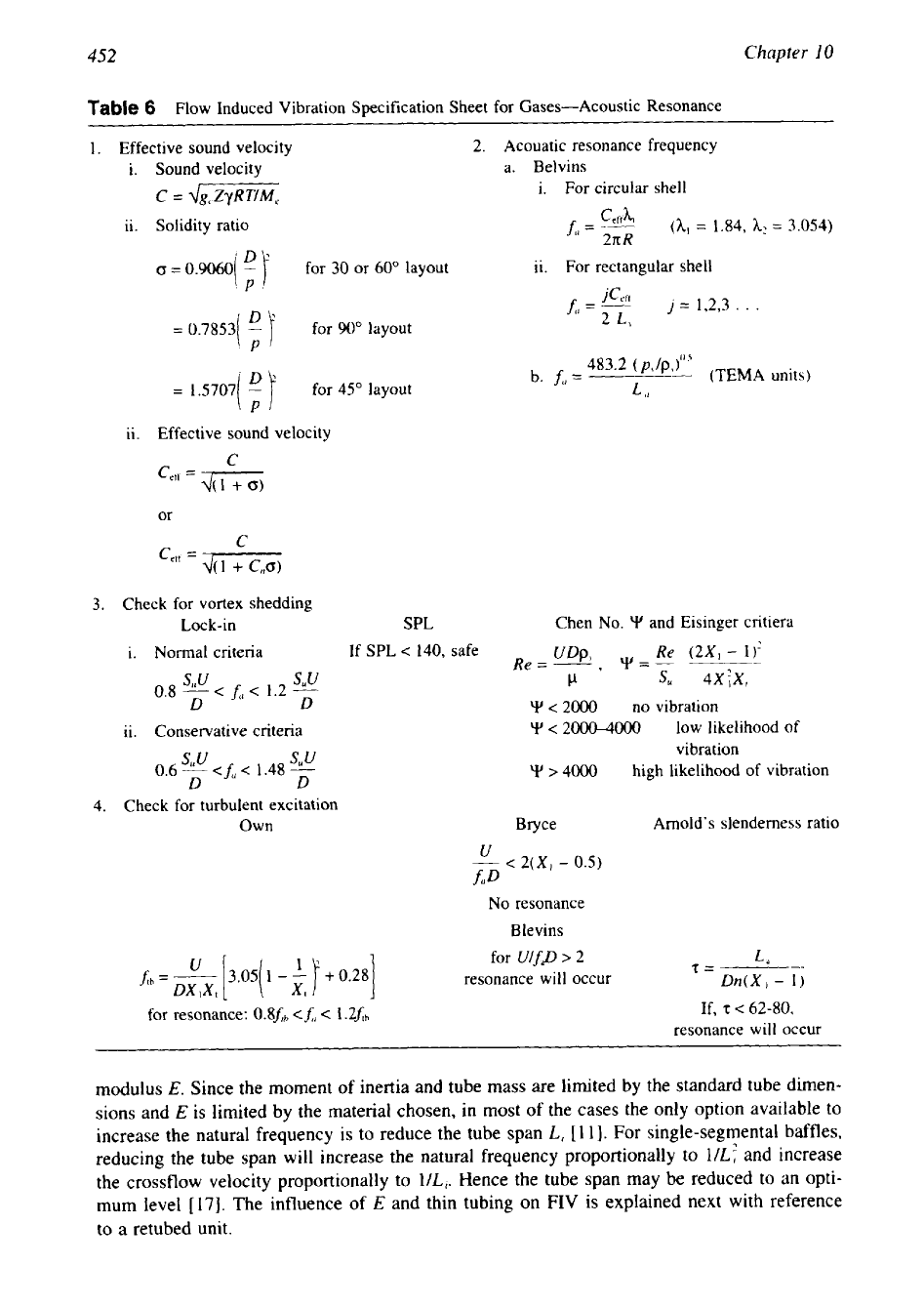
Figure
18
Support plates in
NTIW
to divert fluid across the tube bundle.
FIV of Retubed Units
The importance of tube support spacing and young's modulus has often come to light when a
condenser that was initially fitted with copper alloy tubes, is retubed with thin titanium tubes,
which have a relatively low modulus of elasticity. The thin-wall titanium tubing is not as stiff
as the copper tubing it replaces,
so
that it usually requires supplementary support to avoid
flow-induced vibration problems.
1.
If the tube vibration problem is anticipated in the window zone due
to
longer tube span
between baffles
(2&)
and higher velocity than the tubes at central zone, eliminate the
tubes in the window zone, resulting in a no-tubes-in window design
(NTIW).
To
offset
any loss in heat transfer, introduce support plates as shown in Fig.
18,
to divert the fluid
across the bundle.
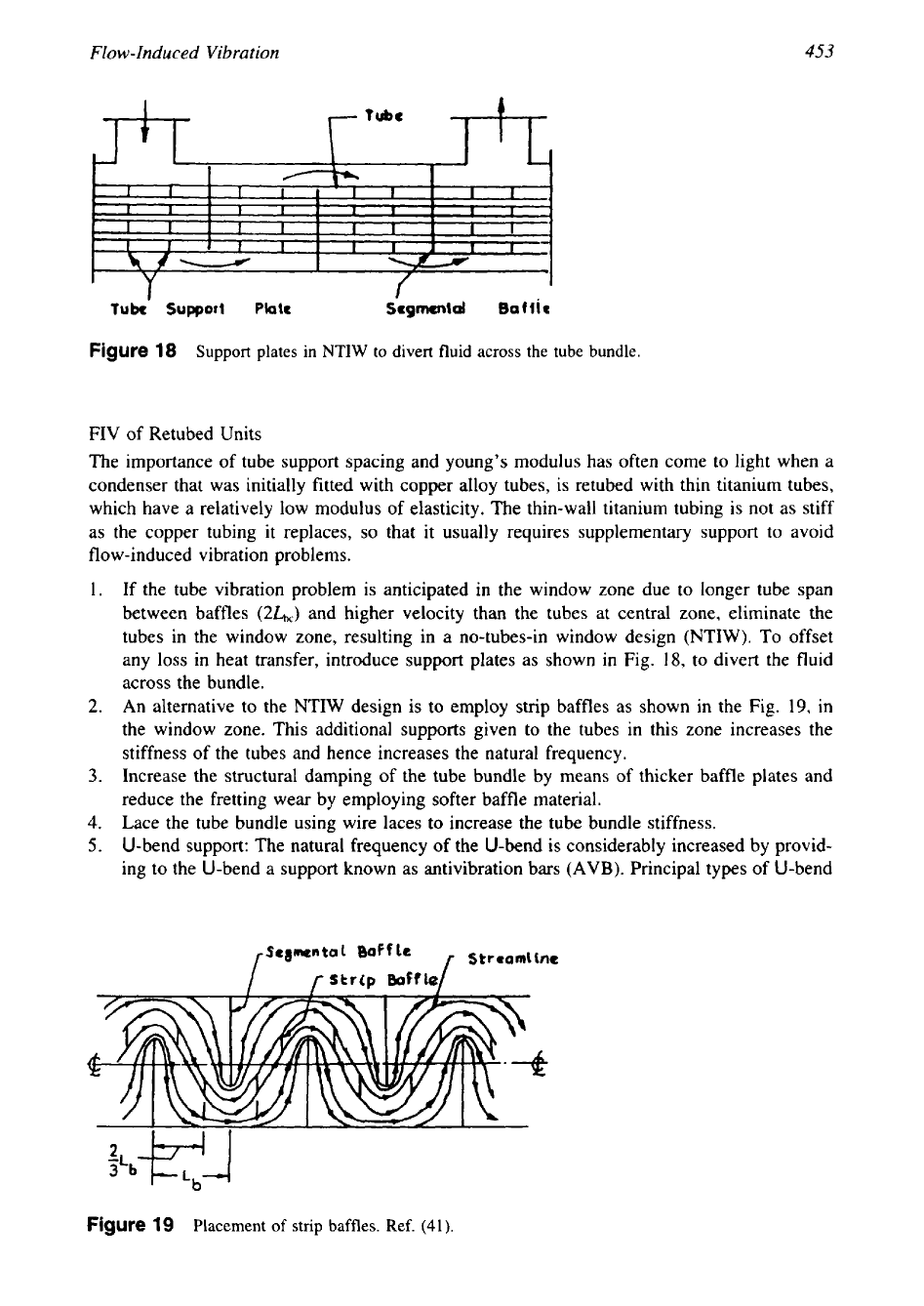
2.
An alternative to the NTIW design is to employ strip baffles as shown in the Fig. 19, in
the window zone. This additional supports given to the tubes in this zone increases the
stiffness of the tubes and hence increases the natural frequency.
3.
Increase the structural damping of the tube bundle by means of thicker baffle plates and
reduce the fretting wear by employing softer baffle material.
4.
Lace the tube bundle using wire laces to increase the tube bundle stiffness.
5.
U-bend support: The natural frequency of the U-bend is considerably increased by provid-
ing to the U-bend a support known as antivibration bars
(AVB).
Principal types
of
U-bend
I
I 1
Figure
19
Placement of strip baffles. Ref.
(41).